14. Networking and communications
This week, we have to learn more on communications protocols and network with microcontrolers.
I plan to use an ESP8266. Then I connect 3 Attiny44 in serial with differents addresses.
ESP8266
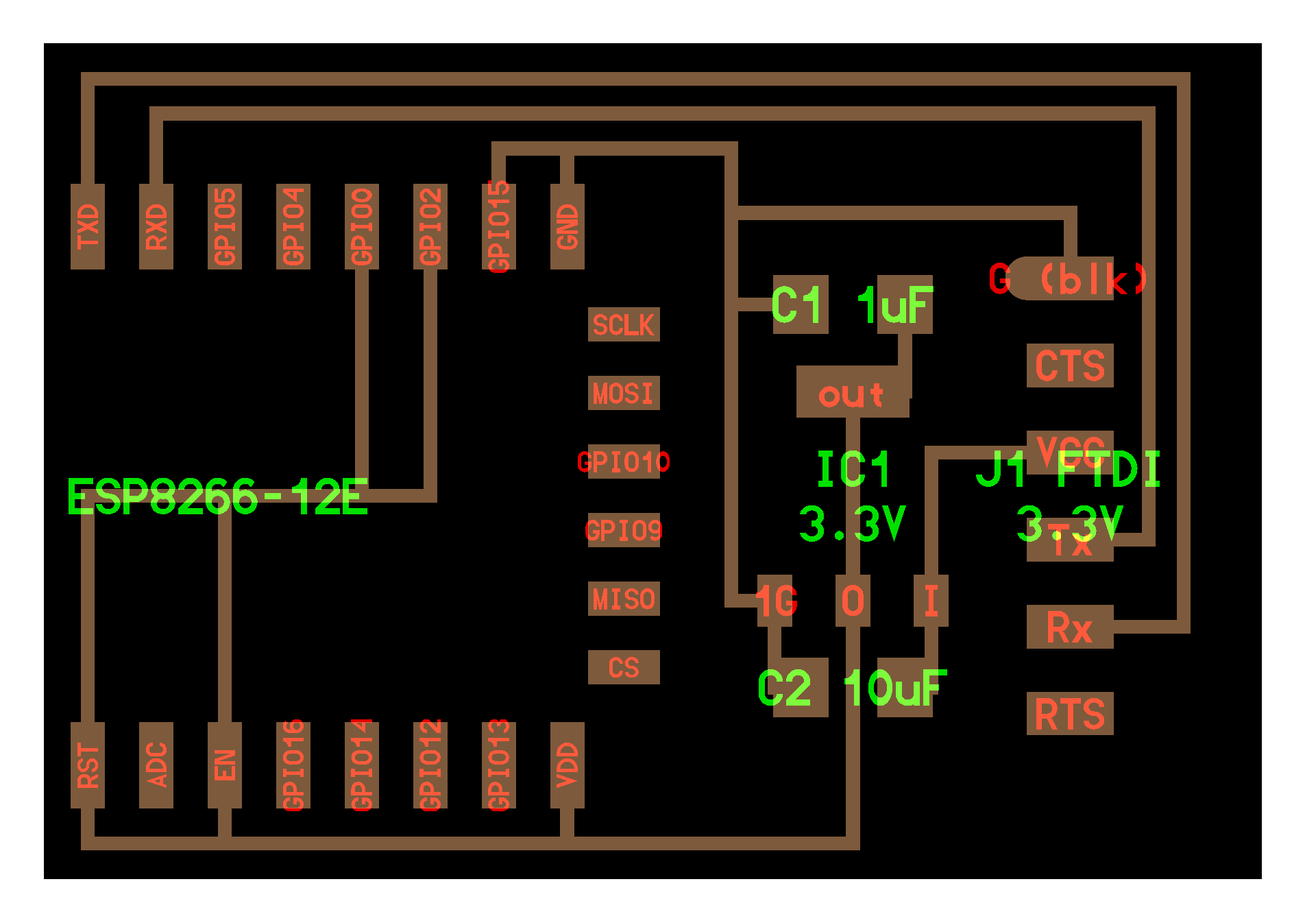
I’ve designed a board with an ESP8266 inspired by Neil’s board but with modification : I want to be able to flash during the bootloader but to have also the serial connections, to have access to the boot pin and to connect an I2C board.
Neil’s board
By reading this document : https://www.elecrow.com/download/ESP-12F.pdf
I’ve discovered that the GPIO0 has several functions
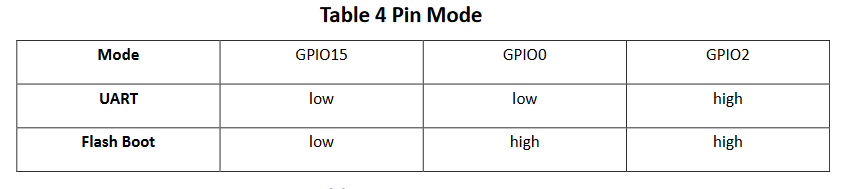
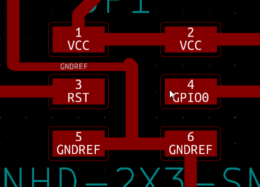
I decide to design several pins to be able to connect either to the ground or to the high value.
the same for the pin RST.
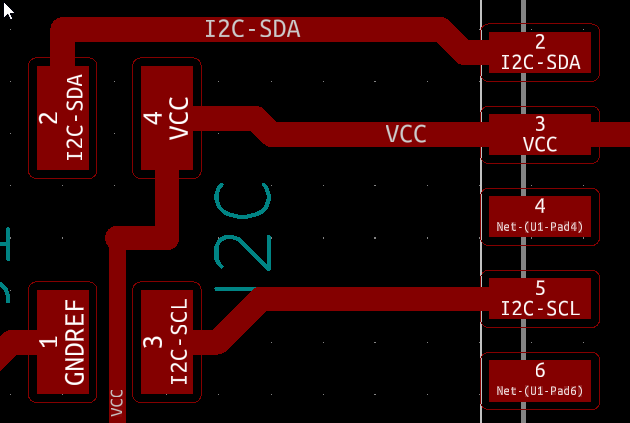
Also, some pin are specialised with hardware I2C :

So I choose those pin for an I2C connector
I also add an LED with a resistor to have a visual check.
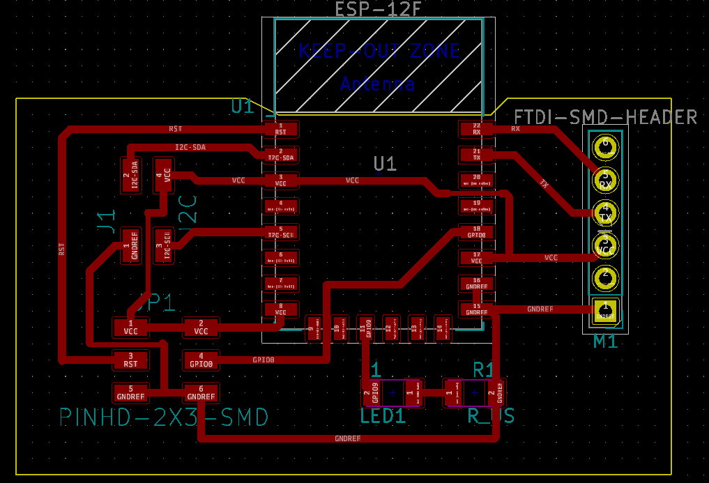
KiCad design
My KiCad design
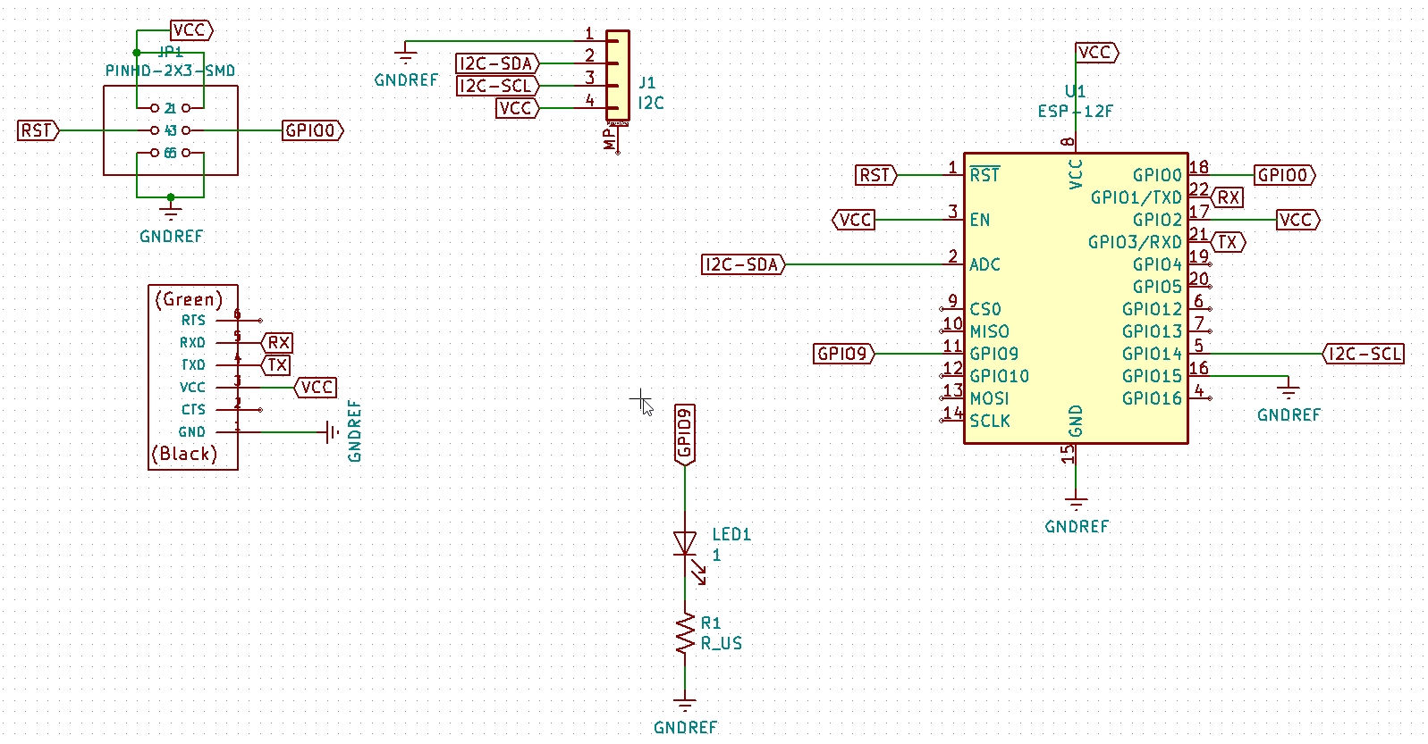
Depending on the convention you use the TX and RX should be swapped.
My Kicad design files : week14-001.zip
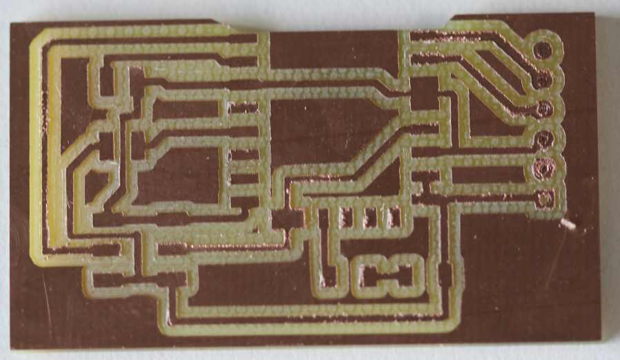
I milled the board. My SVG and RML milling files milling.zip
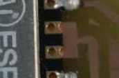
As some path are too close but can’t be thiner, I will not solder some pads that are not used by the ESP8266
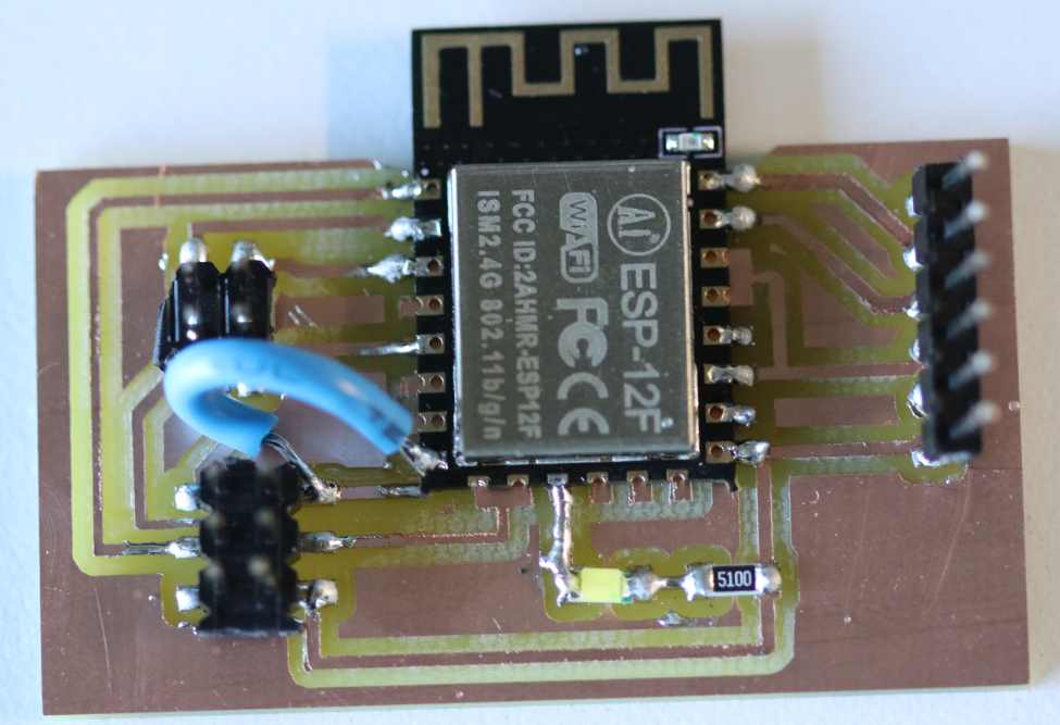
The pads that are not soldered :
 and
and 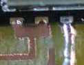
ESP8266
I try to program and flash the code but did not succeed.
I check the electronic connection, they works.
I select the correct board in arduino.
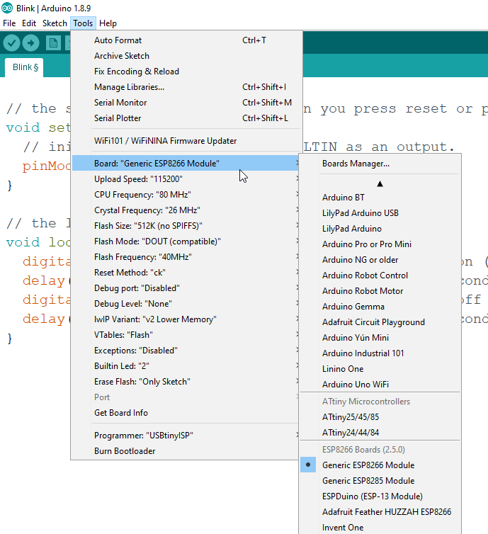
But I got an error message when I upload the code.
Serial communications
I want to validate this week, so I use 3 boards with
I use 2 boards made in the input week and one made in the output week.
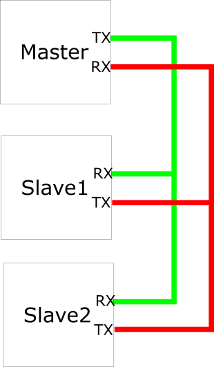
I programm the output board to be the master and to send a “1” message then a “2” message. The 2 other boards light up the LED if they receive the correct number .
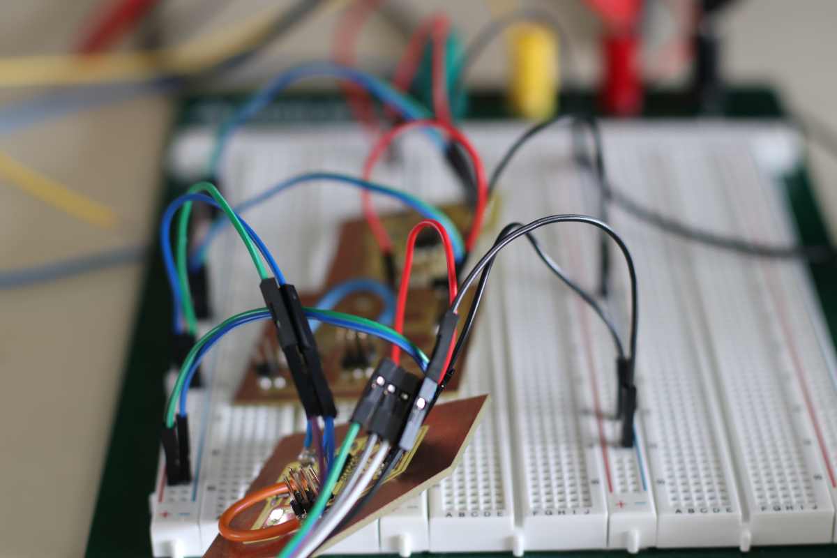
All the board are powered by the same 5V , with a red and a black wire. They share their Tx and Rx with a blue and green wire.
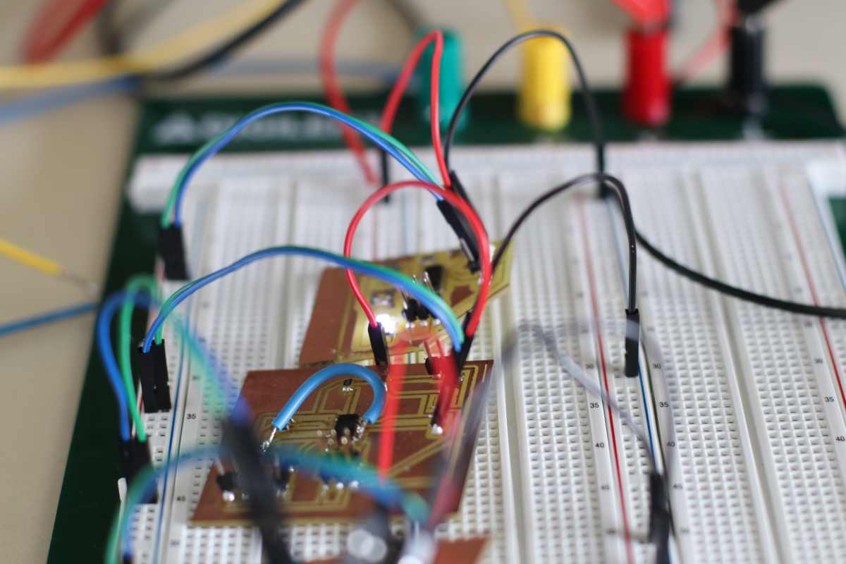
I’ve also added an FTDI connected to my computer to check the messages.
The Master code , mastertx.ino :
#include <SoftwareSerial.h>
#define rxPin 0
#define txPin A1

SoftwareSerial serial(rxPin, txPin);

void setup() {
  pinMode(rxPin, INPUT);
  pinMode(txPin, OUTPUT);

  serial.begin(9600);
}

void loop(){

  serial.print(1);

  delay(2000);

  serial.print(2);

  delay(2000);

}
One receptor board , recepteur1.ino :
#include <SoftwareSerial.h>
#define rxPin 0
#define txPin A1

#define LED 7
#define button 8

int rxbuffer;

SoftwareSerial serial(rxPin, txPin);

void setup() {

  pinMode(rxPin, INPUT);
  pinMode(txPin, OUTPUT);

  pinMode(LED, OUTPUT);
  digitalWrite(LED, LOW);

  serial.begin(9600);

}

void loop(){

  rxbuffer = serial.read();

  if(rxbuffer == '1'){
      digitalWrite(LED, HIGH);
  } else if(rxbuffer == '2') {
      digitalWrite(LED,LOW);
  }

delay(1000);
}
The other receptor board , recepteur2.ino :
#include <SoftwareSerial.h>
#define rxPin 0
#define txPin A1

#define LED 7
#define button 8

int rxbuffer;

SoftwareSerial serial(rxPin, txPin);

void setup() {

  pinMode(rxPin, INPUT);
  pinMode(txPin, OUTPUT);

  pinMode(LED, OUTPUT);
  digitalWrite(LED, LOW);

  serial.begin(9600);

}

void loop(){

  rxbuffer = serial.read();

  if(rxbuffer == '2'){
      digitalWrite(LED, HIGH);
  } else if(rxbuffer == '1') {
      digitalWrite(LED,LOW);
  }

delay(1000);
}
It works as you can see on the video below ,
The master send “1” on the TX wire, the twos board received it on their RX wire, only the first board light up, then the master wait 2 seconds, then the master send “2”, the first board switch off the LED and the second board switch on the LED.
A computer display the actual serial message
Conclusion
Many things should be taken in consideration when designing a board with complex microcontrolers.
I’ve worked with factory made modules with ESP8266 or ESP32 and made several projects.
But in the scope of this Fabacademy, time is an issued and I will take more time in the future to program those microcontrolers.
The serial network between several AtTiny will be usefull for the next week group assignement .
The files
Arduino mastertx.ino
Arduino recepteur1.ino
Arduino recepteur2.ino
Kicad design files week14-001.zip
My SVG and RML milling files milling.zip