3. Computer Aided Design (CAD)
This week, we had an introduction to different CAD systems and software. For this week assignment, I have to try and test some of them.
I’ve already worked with several of them. But I’ve discarded some as they were in their first beta version, and were incomplete for several of my previous projects (especially FreeCad seems to have evolved a lot) I tried several software but for this page, I’ve focused on Autodesk Fusion 360 , OpenSCAD and FreeCad .
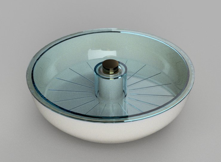
A render of my final project.
Parametric Design - Autodesk Fusion 360
I use Fusion360 for some time now. Before that I used a lot Autodesk Inventor which is more or less the same kind of system. I like the intuitive interface and the integration of different modules : CAM, Render,… It’s also easy to share and work with a team on the same project.
1st sketch and revolution attempt
I want to make at least a visual of my final project idea. As my object has a rotational symmetry, I started by designing a sketch that I’ll revole. I’ll also create several parts assembled together.
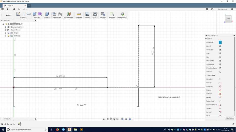
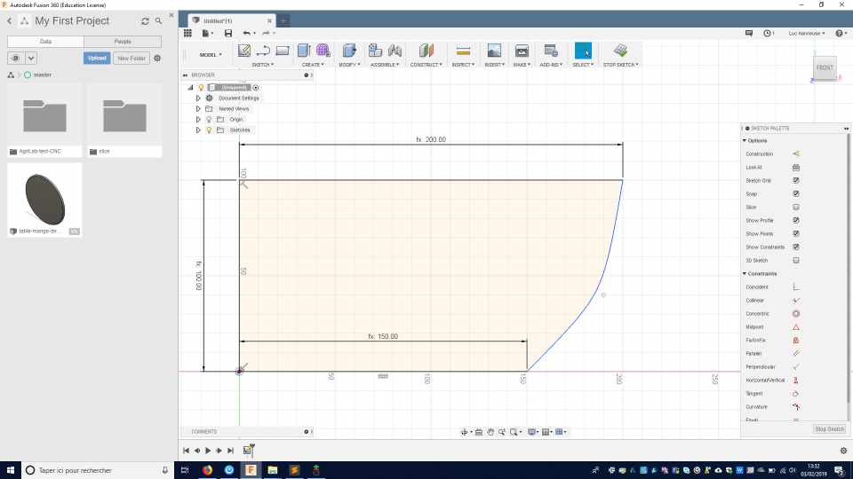
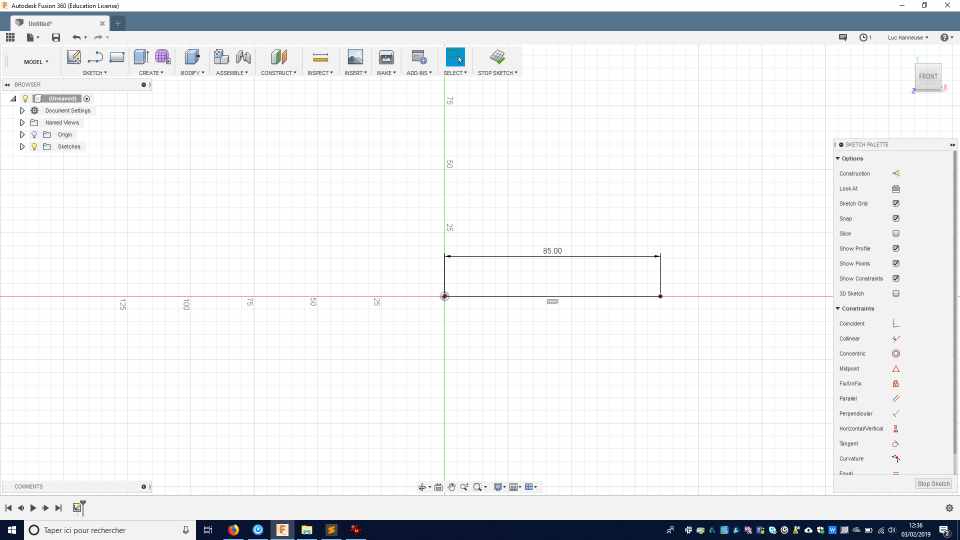 The first error is to directly put dimension. I’ve no precise ideas of all the dimensions. So it’s better to start from scratch with a parametric design.
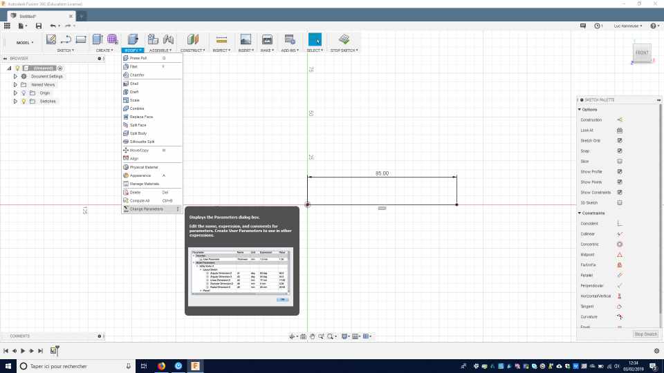
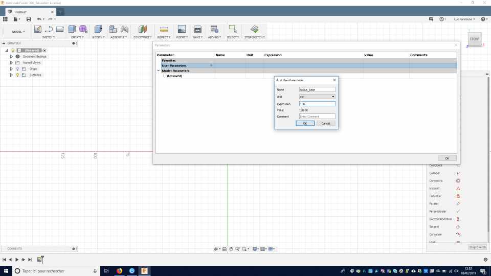
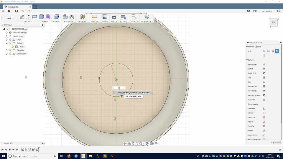
You have to select the parameter dialogue box and create a name and gave an initial value.
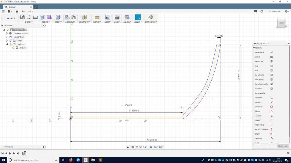
So I create a first value called radius_base with a value of 150 mm.
Then I built 2 construction lines, associated with the radius_medium and the height_medium values.
Then I connect the curves with a conic curve , and chose a Rho value.
Then I built other lines with a material_thickness, and another conic curve.
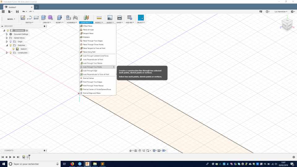
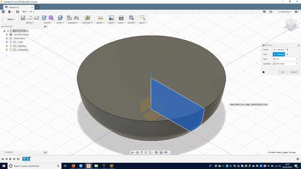
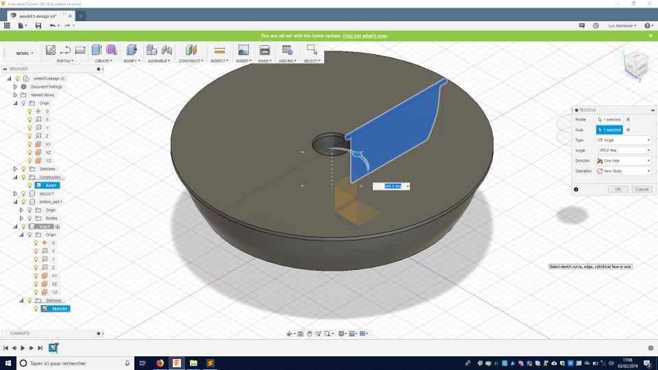
I need to create an axis for the revolution of the revolve tool.
I create the axis using the 2 points axis.
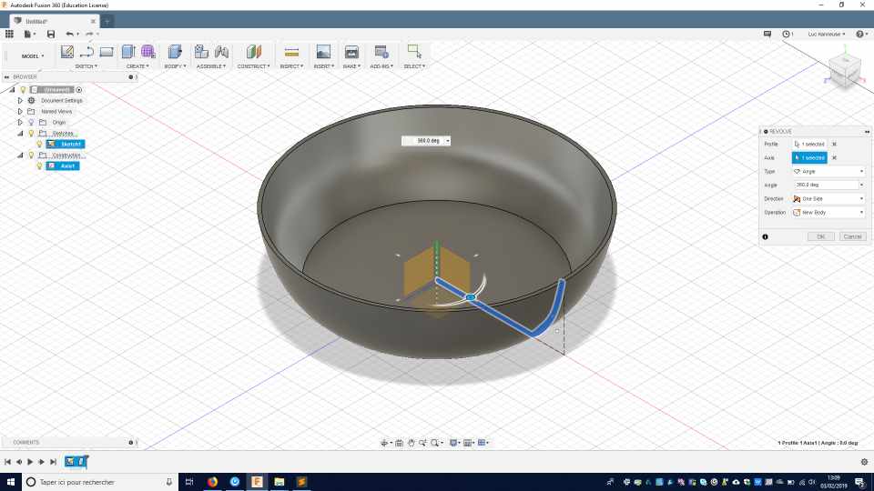
Then, you can see the result of the revolution.
Better method
But this method doesn’t give a homogenous thickness.
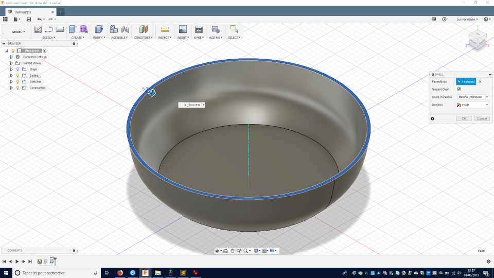
So I tried again, with a simpler method.
I made the sketch without the material thickness.
 And revolve it as a full material.
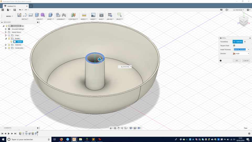
Then with the shell (in modify) tool, I select the upper face and assigned a specific material thickness. With this method I’m sure to have an homogenous thickness.
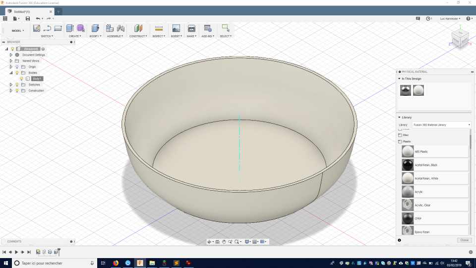
And lastly, I assigned a material property and colour for this part.
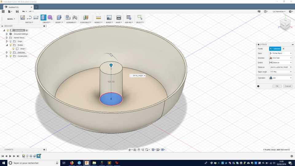
I create another sketch with a circle with the external_diameter of the piezzo element
And extrude the circle as a cylinder .
and make another shell .
Piezzo element
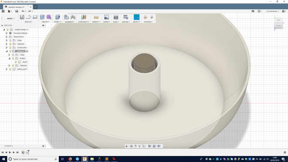
Then I created a new part for the piezzo element body that should be placed at a specific height from the top of the water to create the best amount of mist.
I created a circle and extrude a cylinder and change the material and color proprieties.
Tray
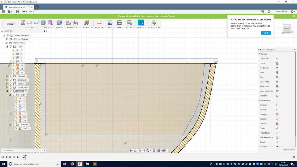
I created another sketch on one of the planes that is going through the axis, and make a projection of the lower part element, so I’ll be able to build my tray profile on it.
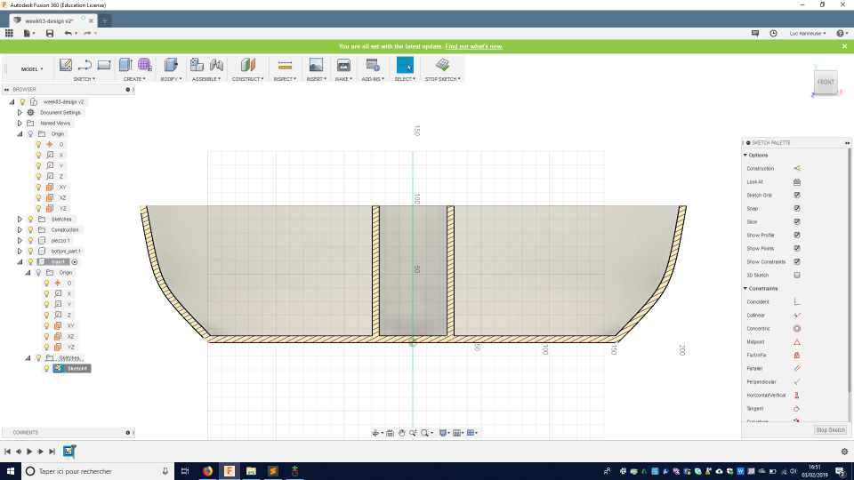
I constructed the sketch on that projection. The sketcheleave some room on the border for the used water to drip. I’m not yet sure of the depth of the tray.

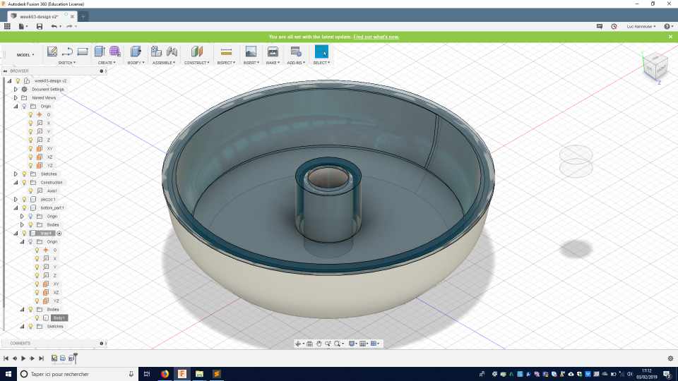
Same again, I revolved the sketch .
and shell the surface. I select a translucent color and material to be able to see through the design.
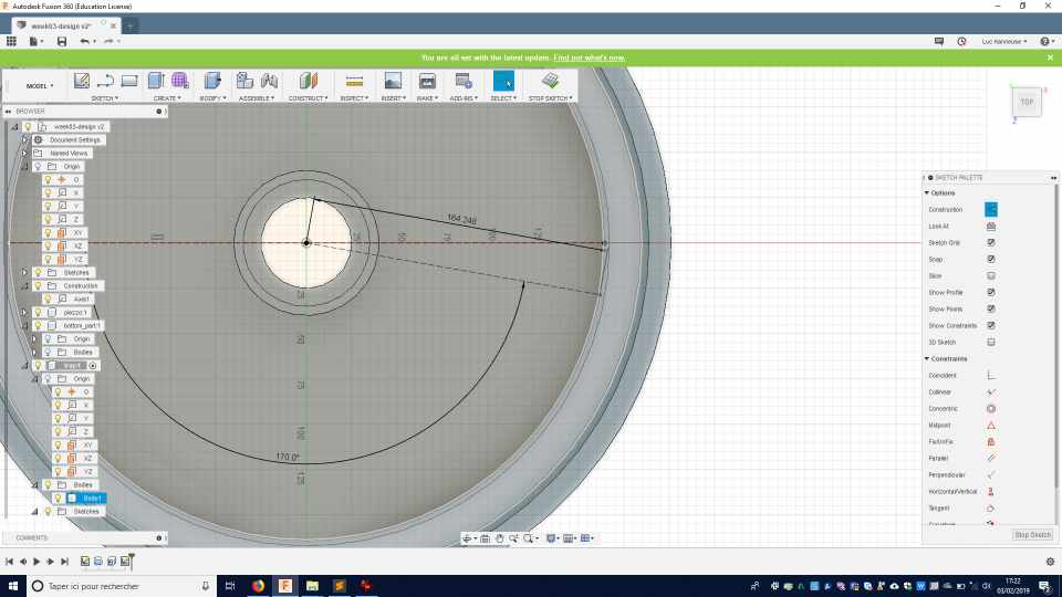
Holes and separation.
I want to create holes so that the used water can drip below, and I want to create micro-separations so the seed won’t cluster together and can be spread all along the surface.
I create one central point and 2 construction lines.
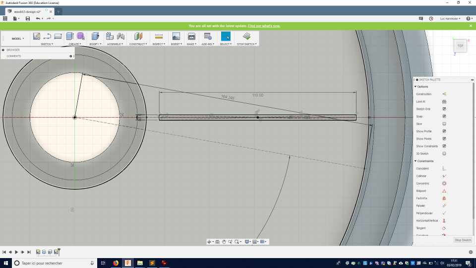
I add another segment and place a mid-point to be able to draw a centred rectangle .
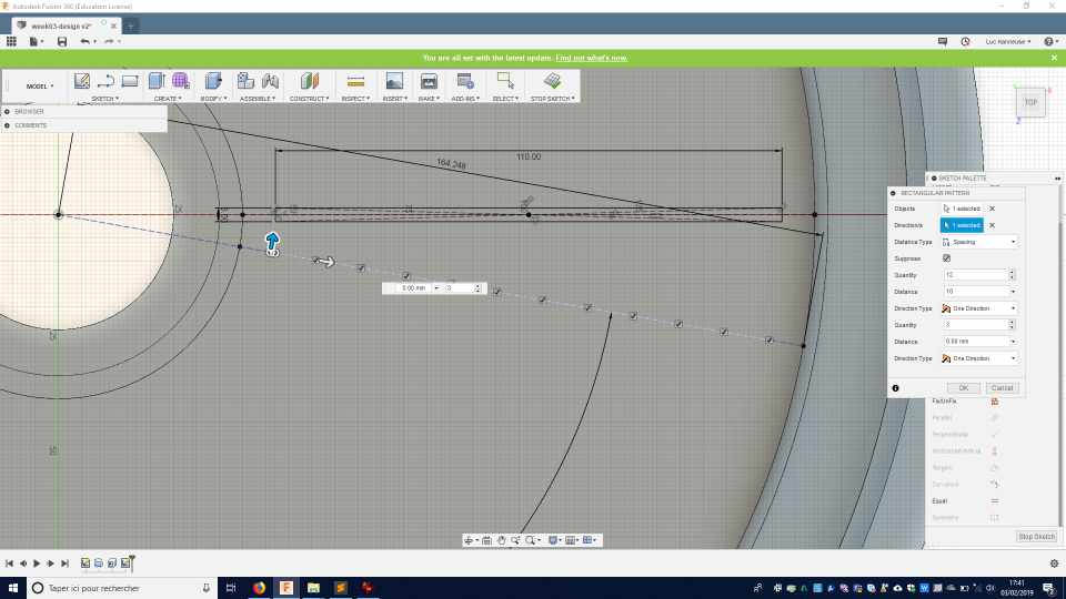
And I create a linear pattern to place about 12 points on a radial axis .
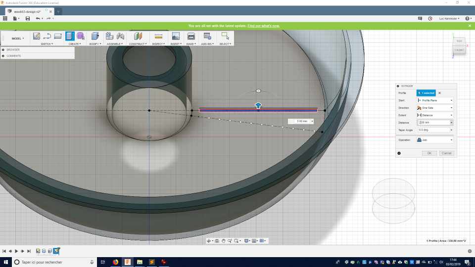
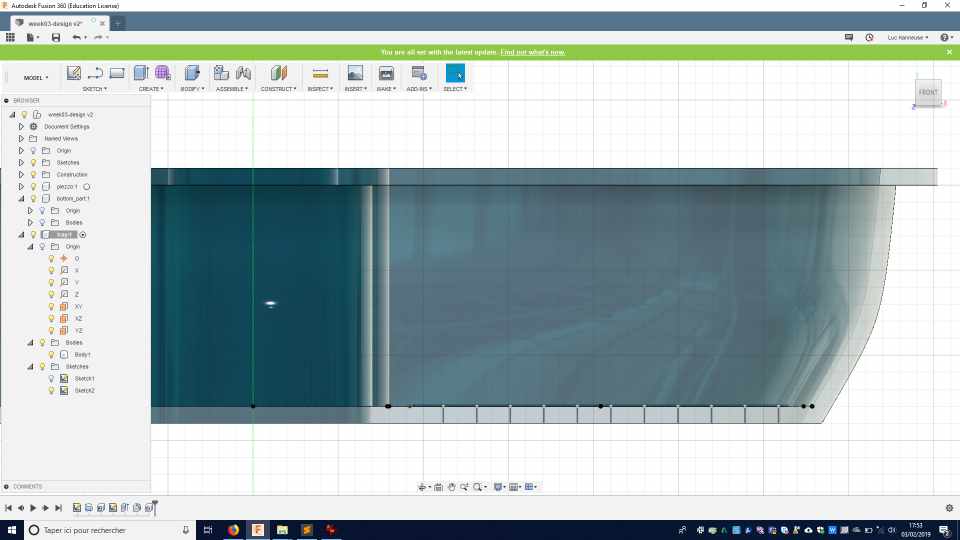
I extrude a small cube from the rectangle .
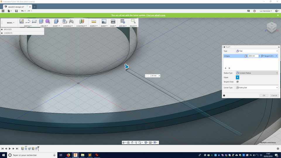
And made a round fillet in the top 4 edges .
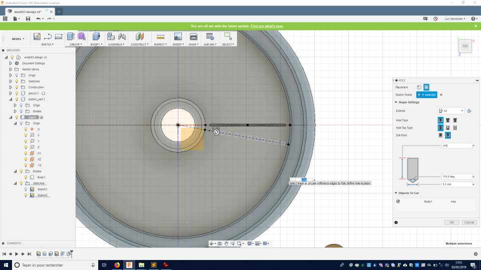
I put holes through the material on the previous points of the sketch .
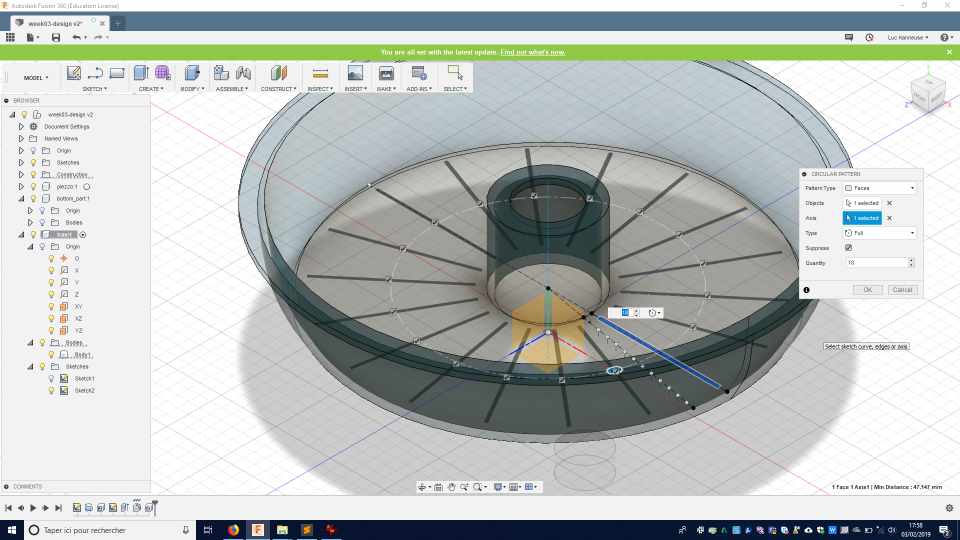
Then I made a circular pattern 18 times the rounded cube shape all along the circular form.
OpenScad - a script-only based modeller
I used previously OpenScad but mainly to edit already existing files that I found on the Internet. So I had to learn to create something from scratch.
To install Openscad, go to the download section of their website, download and install the file. It’s straightforward so I won’t go into detail on the installation.
I follow a part of the OpenScad documentation
Square and rectangles
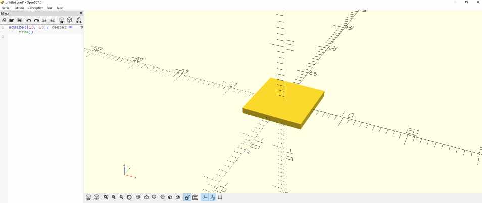
This was created with this square([10, 10], center = true);
When you change a dimension parameter , like replacing 10 by 20 then you have to refresh the view and it’s displayed.
square([10, 20], center = true); For the geometry expert, it shouldn’t be called a square but a rectangle!
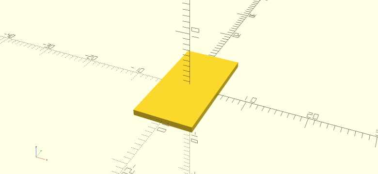
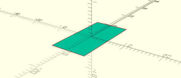
I’m still in 2D dimensions. But in the normal visualisation mode you see a 3D shape. I’ve launched a render and the result is correct with a 2D shape.
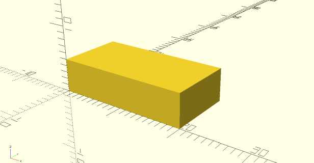
Cube
Then I create a cube with cube([20,10,5]); the valour corresponds to the width and not the positions of the points. And by default it’s positioned on the 0,0,0 coordinate.
To create the cube at another position, you have to translate it first, like
translate([1,2,3]) {
  cube([2,3,4]);
}
![]()
Visualisation
It’s difficult to actually see the position of 3D elements on a screen, So it’s a good idea to play with different visualisation or camera position.
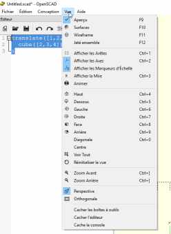
OpenScad offer classical Euclidian point of view and you can access them with keyboard shortcuts like CTRL+4 to see from the top position.
Another classical feature is to play with the mouse. By right-clicking and moving your mouse, you can rotate your camera. The middle mouse wheel play on the zoom, and the right button mouse displace the camera. With those 3 buttons, you can manage any position.
I won’t explain much more of the basic functions, they are many good tutorials on that subject. I think I have a good idea of this software and I’ll be able to use it or recommend it for specific projects or members.
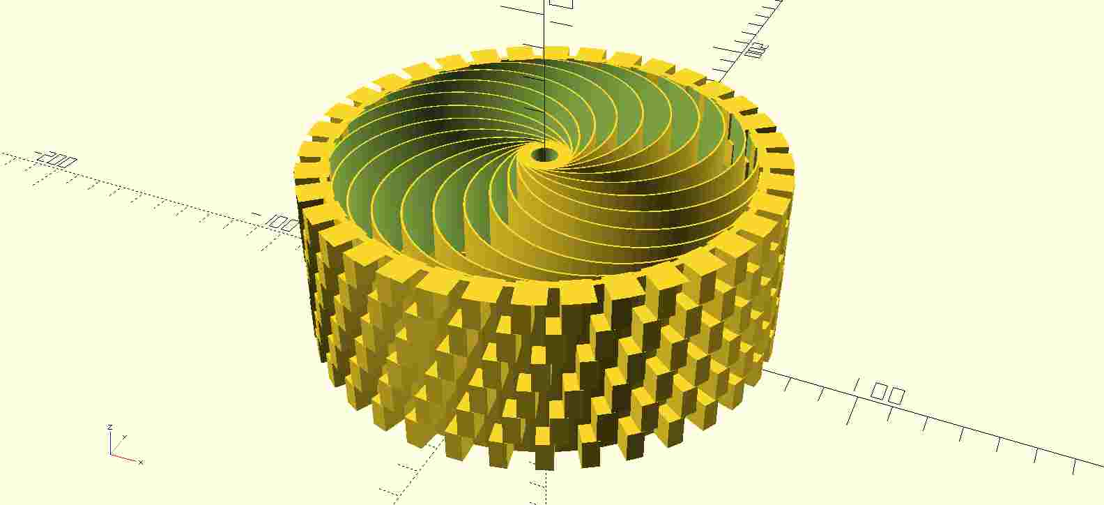
A customizable 3D printable wheel
My colleague Florent Lemaire works with me at AgriLab. He helped students by modifying the file for a wheel in OpenSCAD. It has been printed and mounted on Agricutlure prototyped robot.
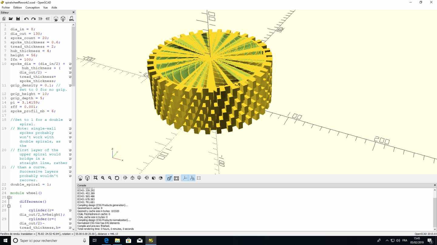
here is the beginning of the OpenSCAD file, as you could see, they are many parameters that can be modified
dia_in = 8;
dia_out = 130;
spoke_count = 20;
spoke_thickness = 0.6;
tread_thickness = 2;
hub_thickness = 4;
height = 56;
$fn = 100;
spoke_dia = (dia_in/2) + hub_thickness + (dia_out/2) - tread_thickness+spoke_thickness;
grip_density = 0.1; // Set to 0 for no grip.
grip_height = 10;
grip_depth = 5;
pi = 3.14159;
zff = 0.001;
spoke_profil_nb = 6;
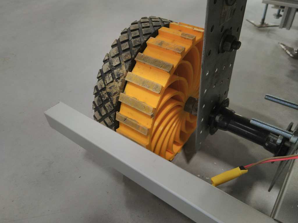
And the result used in the real situation mounted on a robot.
FreeCAD
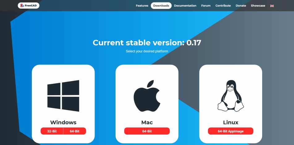
To install FreeCAD, just download the file and install it. https://www.freecadweb.org/downloads.php
Freecad has become a powerful tool that as evolved in many directions.
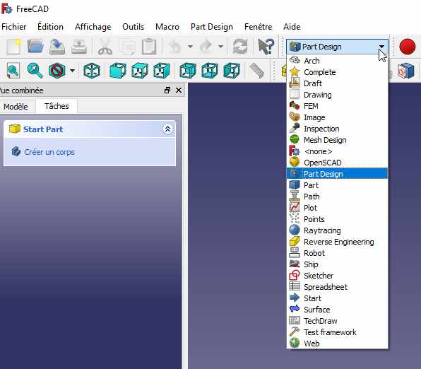
The different tools are accessible through workbenches. I select the Part Design, Sketch and Part workbenches for CAD design.
Part workbenches
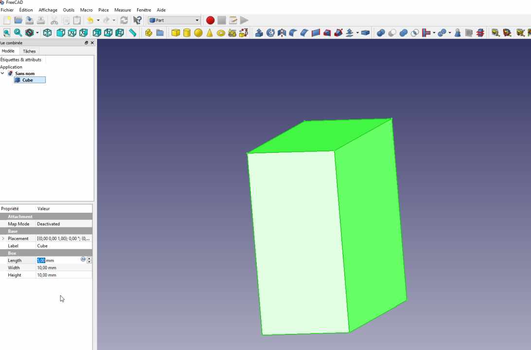
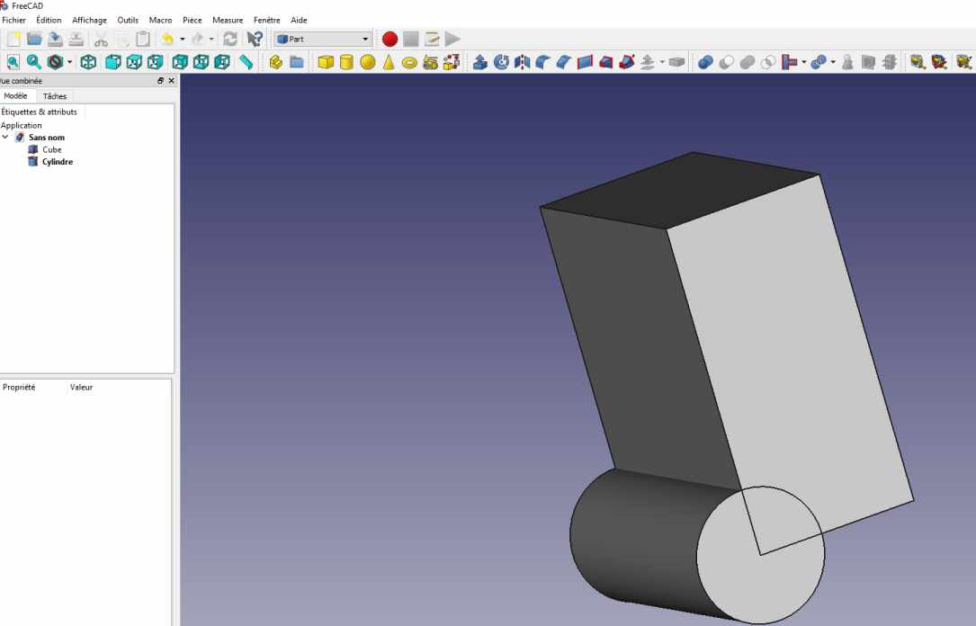
I draw a cube
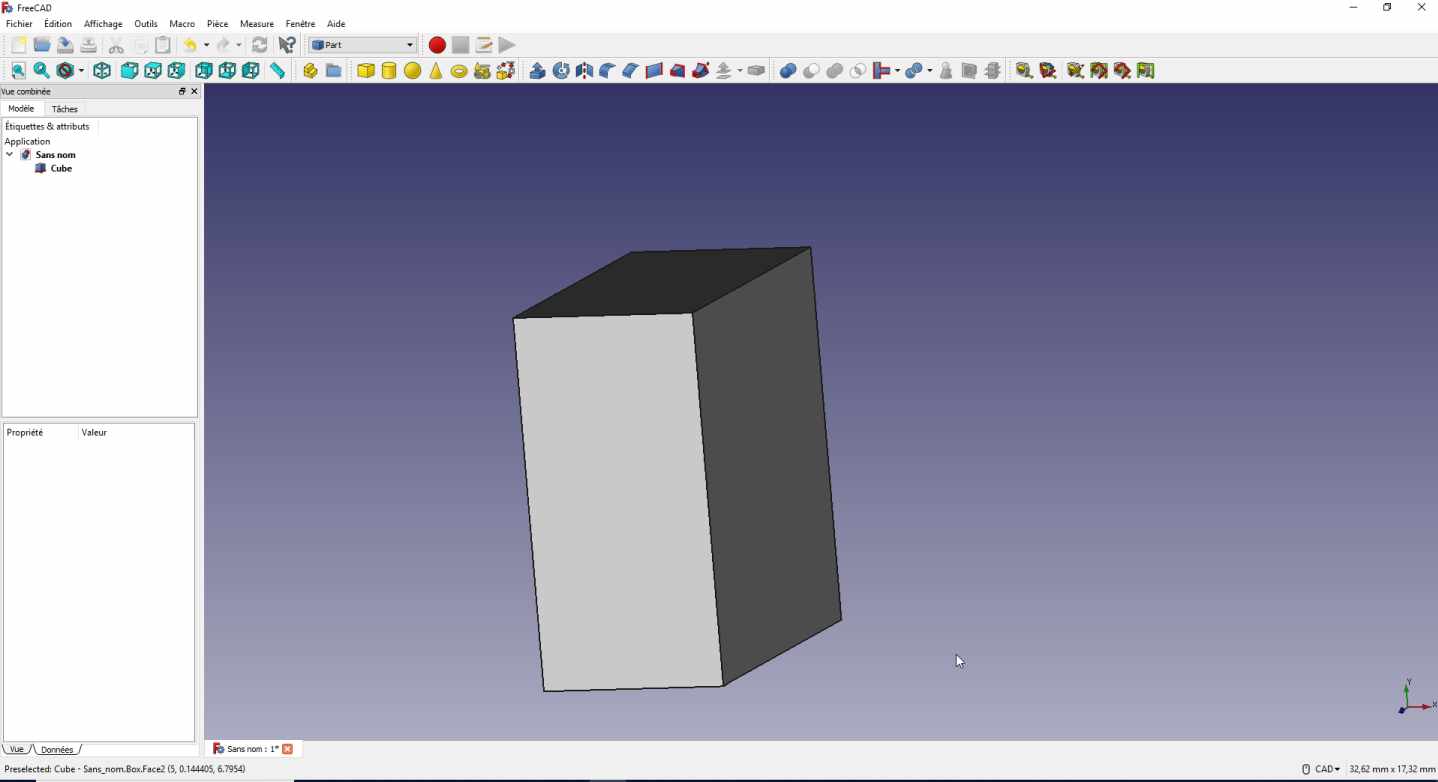
and modify the properties and valours
Then I add a cylinder, so now I have 2 primitive shapes.
Boolean operation on shapes.
I apply a boolean subtraction to create another shape. Note that the order of selection is important ! You have to first select the shape you want to keep and secondly select the shape you want to remove.
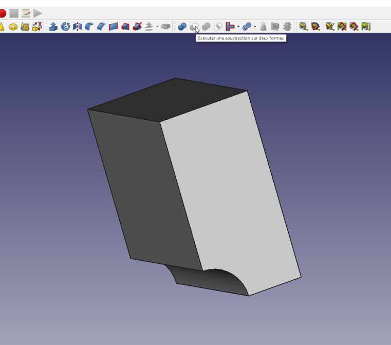
Otherwise you have another result. Here I first select the cylinder then the cube.
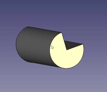
Then I played with some of the tools.
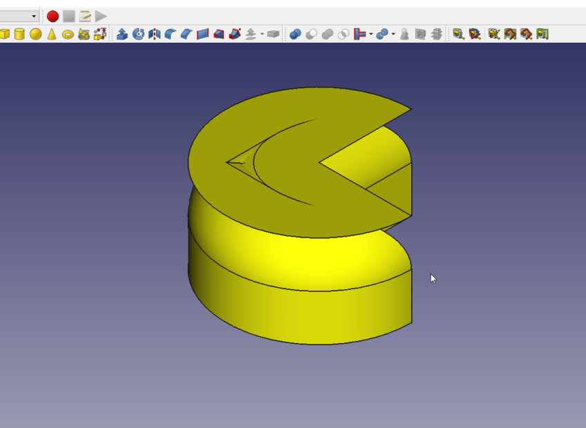
I’m afraid that FreeCAD is still in Beta version. Because I had many visual glitches. Like this one, by just applying a fillet on some edges.
Part Design workbenches
When you switch to the Part Design Workbench then you can draw sketches on 2D face and extrude or revolve.
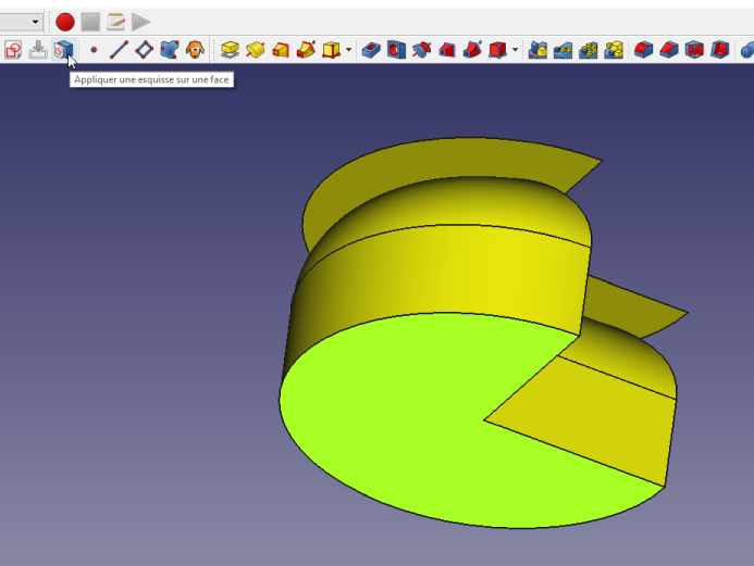
Then you have access to the Sketch workbenches
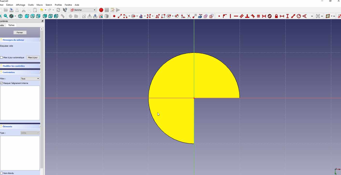
I draw on one of the faces
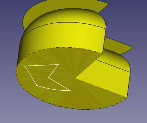
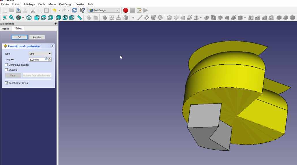
Then I extruded the sketch in a volume.
My conclusion on 3D CAD software
I think each person needs to find the best way for him to work. And depending on the project software can be more specialised. I’ve in the past use some software to design a part and another software for another part, just because it was quicker or easier.
I also hope that you have a better idea of the shape of my final project.
2D with inkscape
I played a lot in the past with inkscape, illustrator.
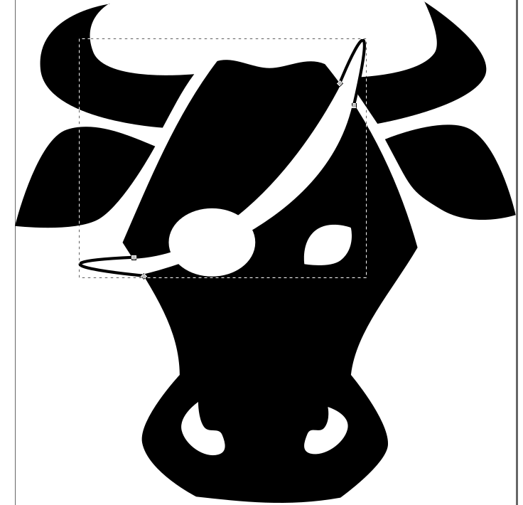
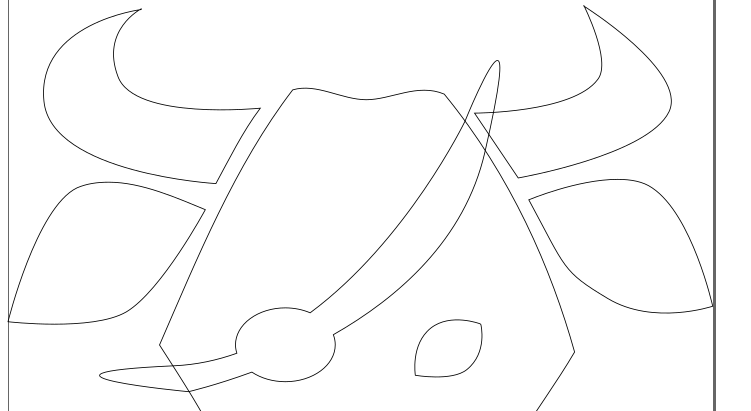
Here, I have taken a picture from internet, https://openclipart.org/detail/194018/cow , it’s fully opensource. I add some lines and circles.

The picture I made

and a screenshot.
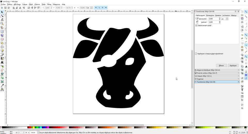
I will probably make some stickers of that design.
I’ve first draw an ellipse .
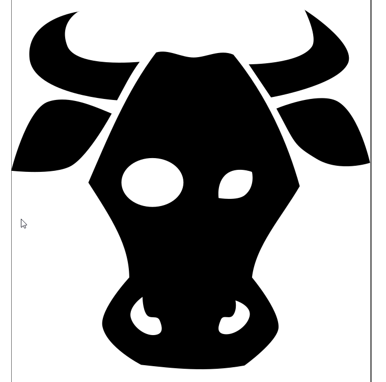
Then I draw some bezier curves. I did not care if it goes further.
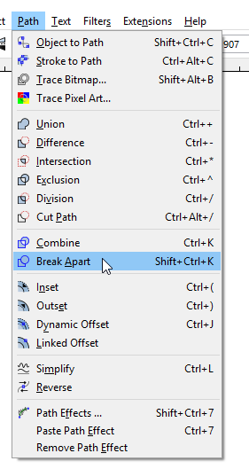
Then I breake apart the different elements.
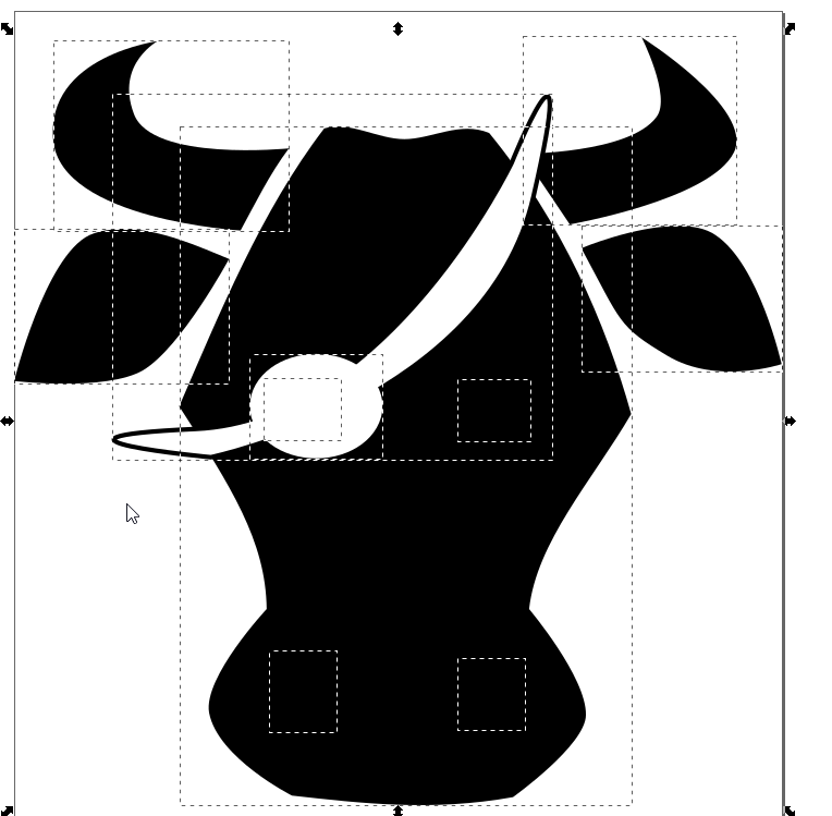
I make several union of elements.
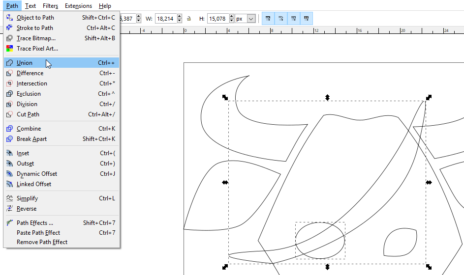
Finally, I made a difference operation of two paths
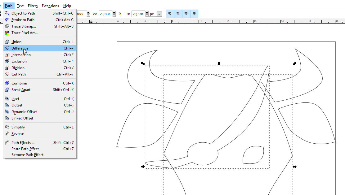
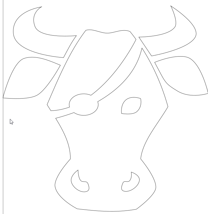
And save the result in SVG format.
My files
My fusion files : fusion-week03.f3d or fusion-week3.step
My inkscape design : cow4.svg