4. Computer controlled cutting
Tasks for current week:
- Group assignment. Done.
- Explain how you parametrically designed your files. Done.
- Shown how you made your press-fit kit. Done.
- Included your design files and photos of your finished project. Done.
- Practice vinyl cutting process. Done.
Vinyl cutting.
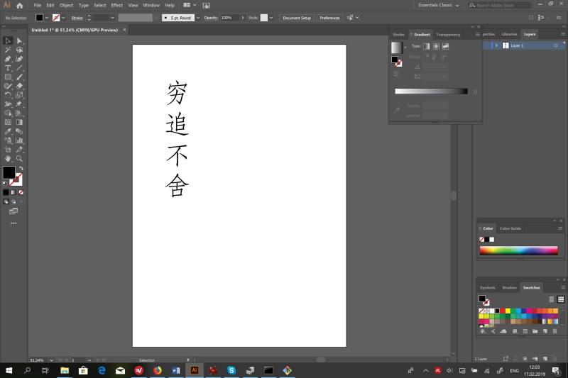
The task was to cut something more or less complex. I decided to make a sticker for my laptop. First, I designed the sticker in Illustrator, and then I transferred the file into a vinyl cutter app.
The design of for the vinyl cutter was made in the Illustrator.
However, I realized that directly cutting letters on the vinyl cutter does not provide a good result, as the letters are small. Therefore, I have decided to cut in the “negative” way. I have cut the squares and cut out the letters out of these squares.

And then I sent the file to print.

After I cut the sticker, I took out unnecessary parts.

To easily stick it on the surface of my laptop, I used paper tape.

After that, I removed the white paper base and applied the sticker to the surface of my laptop.

Group assignment
There were several objectives for our group work:
- Practice using a laser cutter.
- Try different laser setting to find out the best way to cut material, engrave and stroke.
- Work with different materials: plywood and cardboard.
- Calculate kerf for specific laser settings and material
- Cut the “comb” out of cardboard with a different thickness of each tine.
What I have learned:
- Find the relation between speed, power and PPI and how it affects the results.
- Learned how to locate pieces of the board to minimize the movements of the cutting head while cutting and engraving.
- Learned how to calculate kerf.
- See the difference in measures after the actual cut.
- How to adjust the parameters of the model according to kerf size
The photo-report of the group study:
Happy students:

Engineer at work:

First attempts:

Action!:

Measure the cardboard kerf:

Measure the plywood kerf:

Cut, engrave and stroke the cardboard:

The “comb”:

Setting up power, speed, and PPI for different colors of the model:

Setting up the position of the cutter, and cut and engrave modes for different colors:

Individual assignment.
The purpose of our individual assignments was to learn parametrical design. Parametrical design allows changing measures according to the size of the cutting materials or design needs. Moreover, it allows us to see all the measures in one table.
Parametrical design of the press-fit kit.
The design of the press-fit kit I have started from evaluating the size of the material and kerf. The material was cardboard with a thickness of 6.6 mm. The kerf of the laser cut was 0.4 mm.
Kerf measuring:

Kerf measuring:

I have decided to make the design on the press-fit kit with a locking system that helps to hold the parts together:

The model of the part depends on the measures and the characteristics of the material. For example, the locking system can vary with the thickness of the cardboard and kerf. Therefore, it is highly important to set up all the measures and have an option to change the parameters at any moment. All the parameters are saved in a special table:

After the parameters defined and the model designed, it is possible to see the 3D model:

To demonstrate the effectiveness of the parametric design, we can adjust some measures. For example, we can make the size of the part smaller. Also, we can adjust the thickness of the material. In this case, the locking system size will be changed automatically:

Here we can see the difference before and after the adjustments:

One of the goals for an individual assignment was to demonstrate the ability to design the part that can be flexible. Therefore, I came up with the following design. The cell structure allows bending this part on significant angles. I used the design of the original part as the base for the banding part. The parameters of the original part also can be applied to the banding part:

3D model of the banding part:

The next step was to cut these parts out of cardboard. Therefore, I have created the pattern of each part according to the body of the 3D model and saved the pattern as a DXF file. After that, the DXF file was converted to the format that can be opened in CorelDraw or Illustrator to send this model to a laser cutter:

Cutting process
The setting for the laser cutter are the same as for group assigment, as I use the same cardboard: 65% power and 10% speed.
Open vector files in CorelDraw to send on laser cutter:

The process of cutting:

Video:
Photos and video of the project.
Press-fit kit part 1:

Press-fit kit part 2:

Press-fit parts:

Assembled abstract object:

Assembled abstract object:

Assembled abstract object:

Video presentation: