3. Computer Aided design
Task for current week was:
- Modell experimental objects/part of a possible project in 2D and 3D software. Done.
- Shown how you did it with words/images/screenshots.
- Include your original design files. Done.
The goal
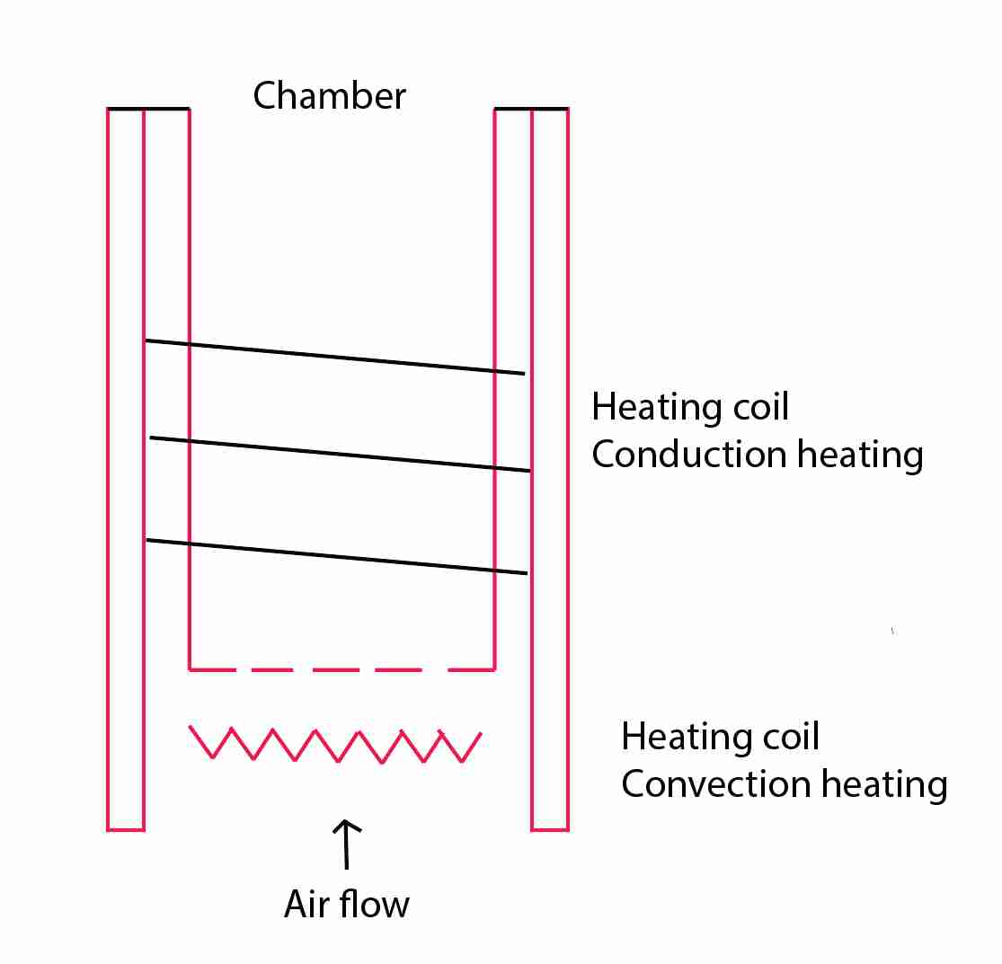
The goal for me was to create the main part of the device for my project. I want to remind that I am going to create the vaporizer that allows consuming medical cannabis. The main part of this device is the heating chamber, where the dried herbs are heated and the medical substances extracted. There are two main types of heating: conduction heating and convection heating. With the conduction heating, the material directly touches the heating area. With the convection heating, the hot air goes through the material and extract the substances. There is more theoretical information regarding the subject in the Final Project section. The difference between conduction and convection heating and advantages and disadvantages of both methods. The device that I create should support both types of heating. Therefore, the structure of the heating chamber can be the most complex structural part of the project. I came up with the following schema of the heating chamber.
However, it is not only important to come up with a certain schema of the part. It is also important to understand the possible production process and materials, as it can create many limitations. Some of these questions I covered in the Final Project section.
2D:
I have selected 2D software according to the following requirements: - I need it to create 2D vector graphics for the laser cutter and vinyl cutter; - I need to edit some raster graphic for presentations - I need the tool that helps me to convert the batch of files according to certain requirements
Illustrator
This 2D software is dedicated to making vector design. I tied this software together with Inscape. I like the interface of the Illustrator. Therefore, I prefer to continues using this tool for my future work.
The sample design made by me in Illustrator.
I have chosen this software for vector graphics because it is easy to use and it is free. One of the recently made works was creation the vector graphics for a vinyl cutter for week four assignment.
I have created typed several letters in Chinese and converted these letters into the numbers of connected lines so that the vinyl cutter can follow these lines.
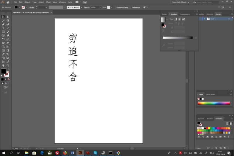
The file created for this assignment is attached. Please check the bottom of the page. Also, I use Illustrator to convert files created in the 3D software into the files understandable for the Laser Cutter. For example, for my final project, I want to make plywood parts.
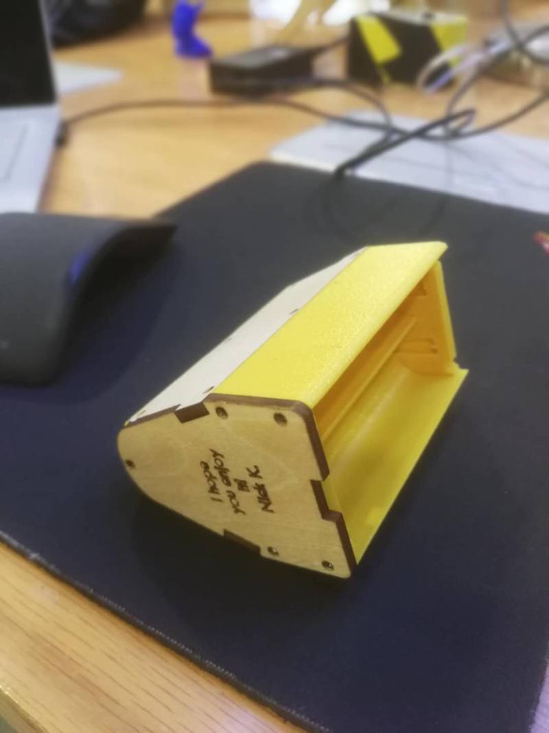
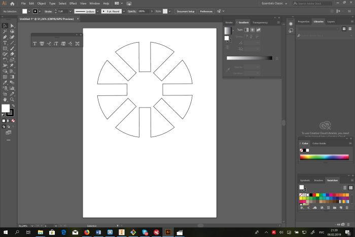
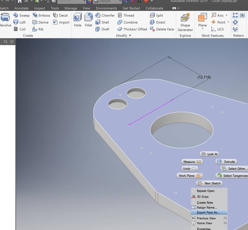
I designed the part in Autodesk Inventor to assemble in the program and see if the connection between parts does not have any issues. Ones I understand that my design is right, I can cut the part out of plywood. However, before I do it, I need to convert the part into the 2D model. I export the face of the model as a DXF file.
Then I open the file in the Illustrator, change the settings for the lines to 0.1 pt.
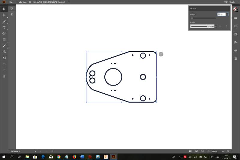
After that, the file can be sent to the laser cutter.
GIMP
I have some experience using Photoshop. I found the interface of GIMP software similar to this program. Moreover, GIMP is free to use. Therefore, I decided to use this application for my future needs. However, right now I do not have many options to use it.
Irfan View
I have chosen this application for simple picture editing and batch conversion.
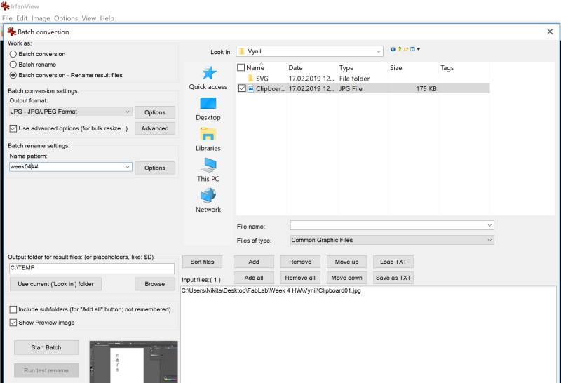
The process of conversion is very simple. The user should choose the files that should be converted in a certain order. Create the pattern for the file name, size set a common setting for quality and file format, and start the batch conversion.
Resulted files will have the same specification. The profiles of the settings can be saved and used for future conversions.
Here you can see the batch conversion window in the program.
3D:
I decided to design my project in 3D. Therefore, the selection of the software is crucial here. I was considering several options for my project: Rhino, FreeCAD, Fusion 360 and Inventor. Eventually, I have selected Inventor as the interface of the program looks most convenient for me.
Rhino
This tool is powerful and easy to use. However, the architecture of the solution is not very convenient for me. The fact that I cannot change some step in the history without cancellation of the steps that were made after this step seems too dangerous for me. As I am not an experienced user and often I do not have a specific schema in my mind, so I want to edit some parameters of the model after I completed it.
FreeCAD
This is a powerful application. But the interface is not very user-friendly. It requires too much time to figure out how to use it effectively. Therefore, I have decided not to use it.
Fusion 360
This software was especially interesting to as it includes Generative design module, that allows creating the shape of the parts by a computer algorithm. The user should define create the pattern for the structure by defining obstacles, preserve geometry, loads and constraints. I used the tutorial on YouTube to figure out how to use this module https://www.youtube.com/watch?v=a_o-rYb8wyo
Unfortunately, I did not have much time to practice with this feature. However, I tried to create the body (the box for the components) of the tool that I am going to create within my project.
Eventually, I got the following result:
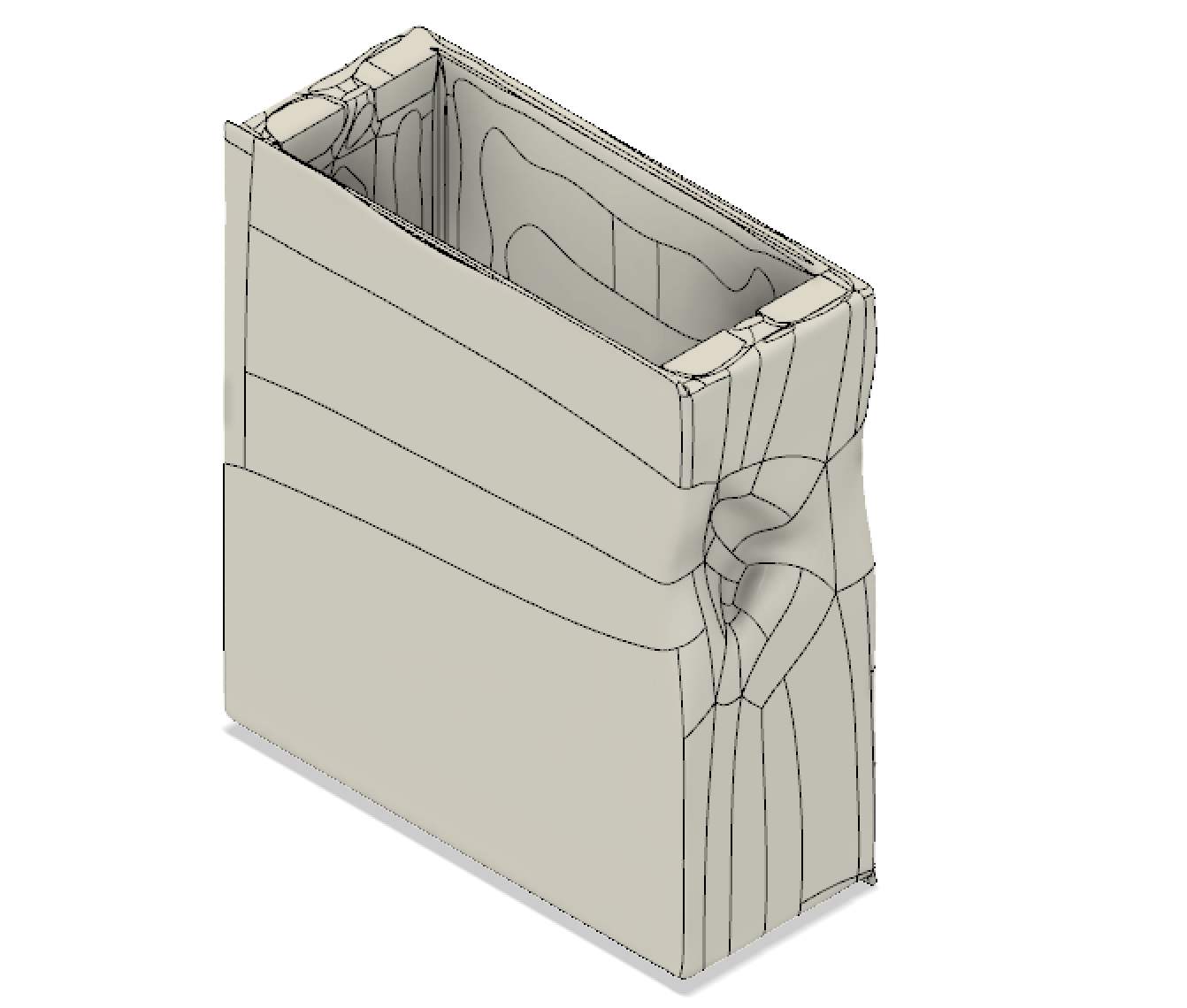
It is not functional and not good looking, but is was nice to understand the principles of work of this tool. I will think about using this module for the future development of my project. However, right not I cannot afford to dedicate more time to learn the usage of the Generative Design module. Another interesting feature that I liked in Fusion 360 was surface modeling. I watched the video tutorial on YouTube and found it very useful to convert the analog design to 3D model.
Surface modeling tutorial: https://www.youtube.com/watch?v=NypRE2aFhh4
Autodesk Inventor
This software has four modules: Part, Assembly, Drawing and Presentation. As we can see, it includes all the necessary features to design the product. It doe not have a generative design. But on this stage, I do not need it. Moreover, for the generative design, I can use other solutions, in case I need it. I like its architecture. I like the fact that I can change the parameters of the designed parts even after I complete the project. To learn more about the features of Inventor, I watched some tutorials on YouTube.
Basic knowledge https://www.youtube.com/watch?v=msXjD96ayIY&t=834s
Circular pattern https://www.youtube.com/watch?v=bXcP-mdLByM
Assembly https://www.youtube.com/watch?v=FqaGonaRBEM
Presentation https://www.youtube.com/watch?v=GXdhsdCbmuo&t=186s
Eventually, I have designed one of the main parts of my project. The chamber that warms up the herbs to produce vape. During the design process, I considered the materials and productions process. Therefore, for example, I excluded all sharp angles from the design to make it possible to produce it with CNC machine.
Issues
However, I still have some issues with clear understanding, how this part should be produced. This question comes from the fact that the chamber should be made out of dielectric material resistible to high temperature. The possible material for this is ceramic. But ceramic is not easy to mill on CNC machine because of the hardness. However, I found some examples on the internet where people produce ceramic parts with CNC machines out of unfired ceramic, that they put in the owen after. I hope that this technology can be relevant for my project too.
Design process
I have designed four parts that are included in the chamber. However, I will should you the process of design of only one part because the design of other parts is more or less similar.
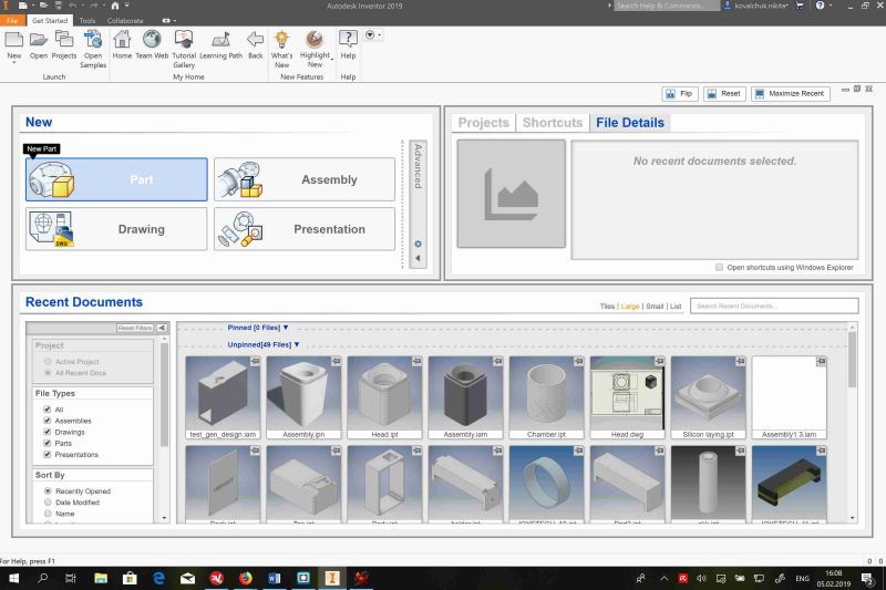
The main window of the application. We can choose the module that we need. To design one part, we should choose “Part.”
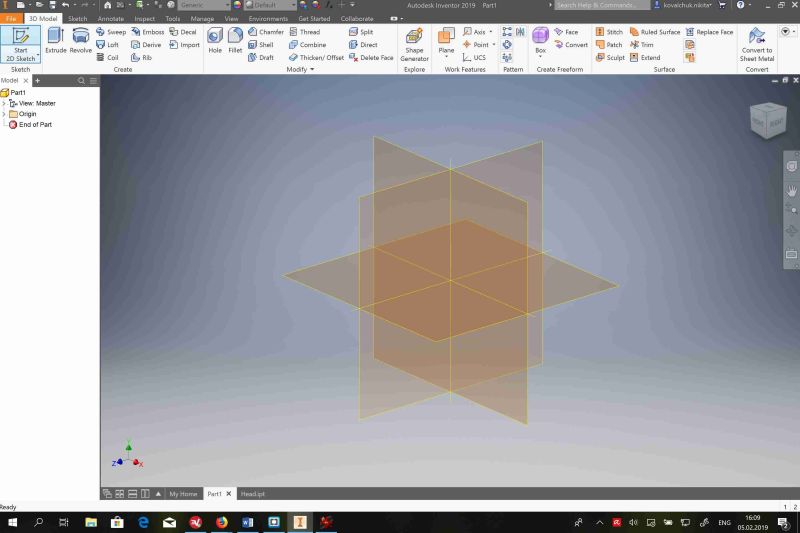
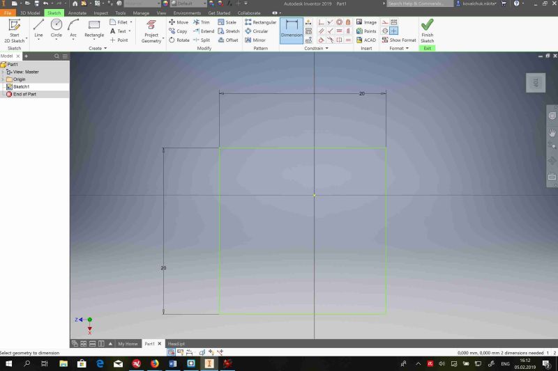
To start creation, we should scetch the base of the part. After that, we can add some specific parameters of the object. We should choose the dimension and chose the form.
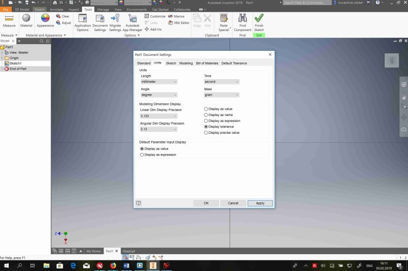
Also, I should set up the document setting. For example, I use the metric system.
My part should look like a square. Therefore, to draw the base, I have chosen “Rectangular.”
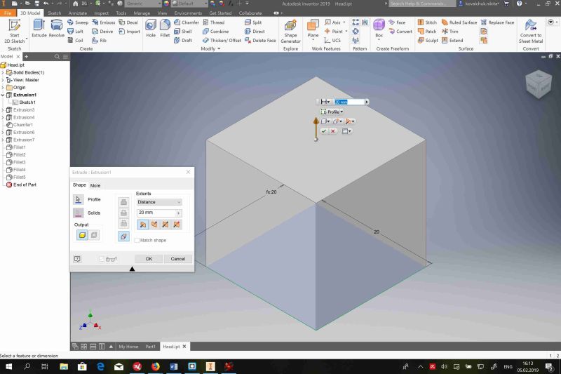
After the sketch is finished, I can extrude it to necessary shape.
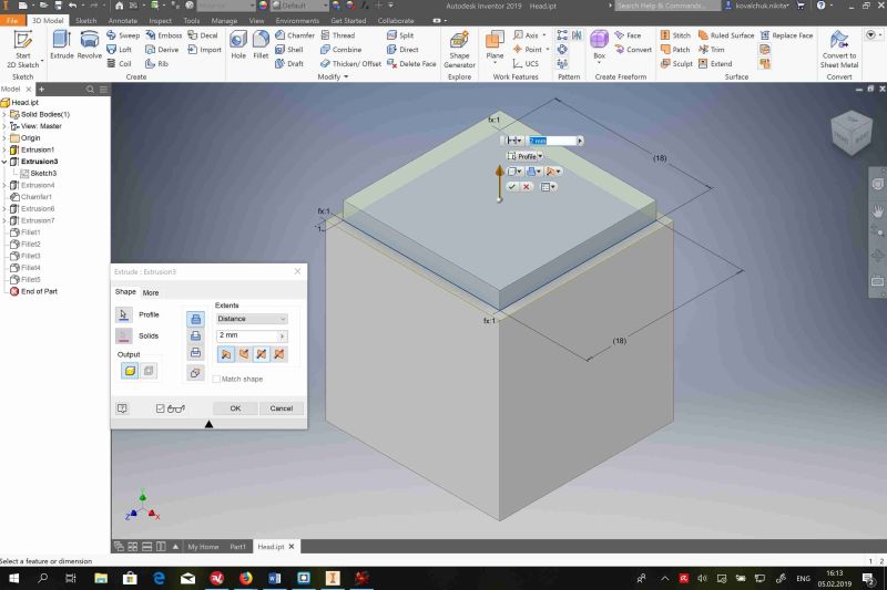
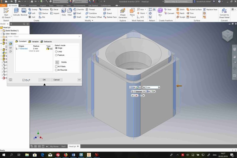
I can add some specific shapes to this part in the same way.
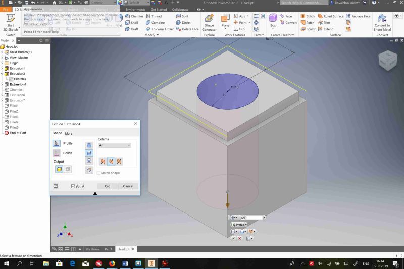
I put the hole in the center of this part. The process is the same, first sketch. Second, extrude or cut.
I do not like the sharp angle. Therefore, I use the Chamfer function to change it.
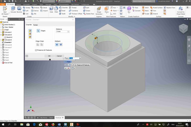
The production os this part will be made with CNC machine. Therefore, I should remove the sharp part as much, as I can.
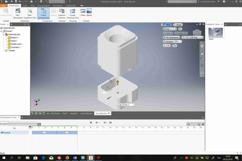
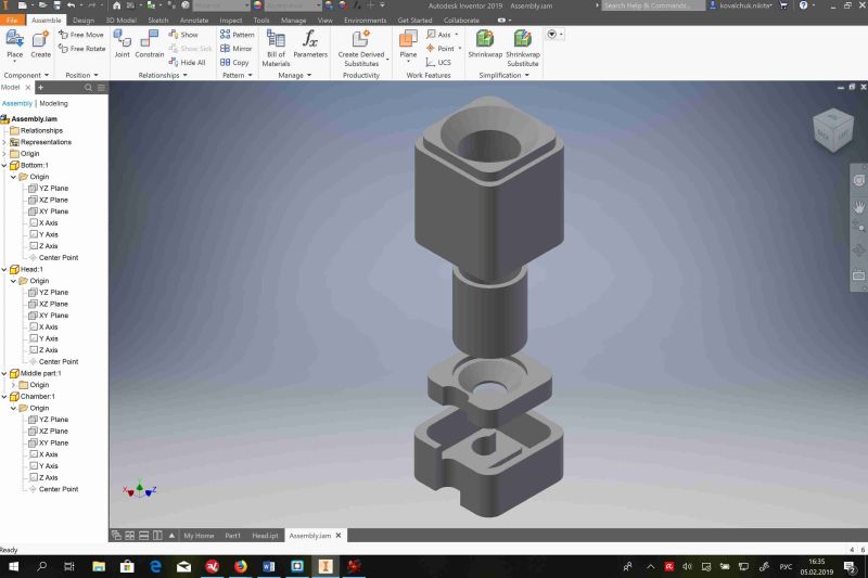
After all parts are ready, I can assemble them in Assembly module.
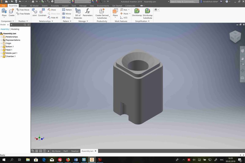
Eventually, the part should look like this.
On the last step, I made a presentation in Presentation module. This module allows creating simple video easily. It only requires to establish certain points of capturing. A programme will do everything by itself.