7. Electronics design
Assignment
individual project:
redraw the echo hello-world board,
add (at least) a button and LED (with current-limiting resistor)
check the design rules, make it, and test it
extra credit: simulate its operation
Learning outcomes
Select and use software for circuit board design
Demonstrate workflows used in circuit board design
Have you?
Shown your process using words/images/screenshots
Explained problems and how you fixed them, including how you worked with design rules for milling (DRC in EagleCad and KiCad)
Included original design files (Eagle, KiCad, Inkscape, .cad - whatever)
What we did
FabAcademy2019-FabLab Kannai lab site
What I have done
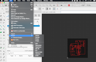
This week I used Eagle to design my circuit board, milled with MDX-15 and FabModule.
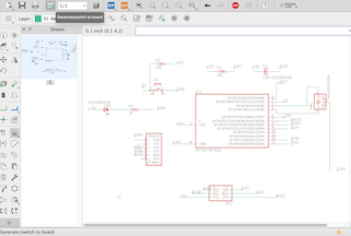
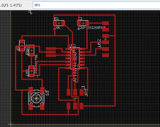
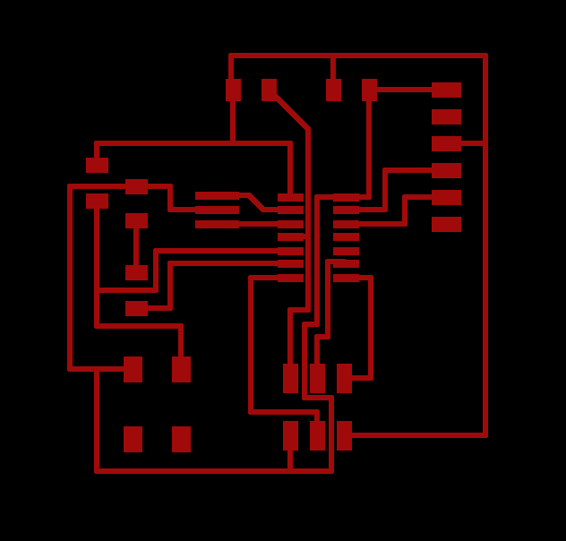
First, I design a board on Eagle.
- Created new board.
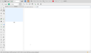
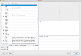
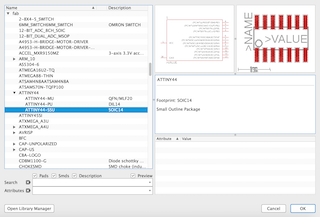
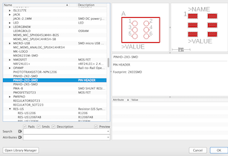
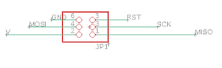
- Added parts from library.
-
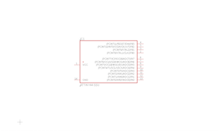
Connected parts by using “name” command
-
Setting the board configulation
-
Placed parts
-
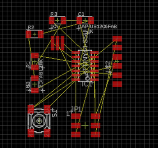
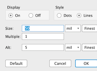
Setting Grid
-
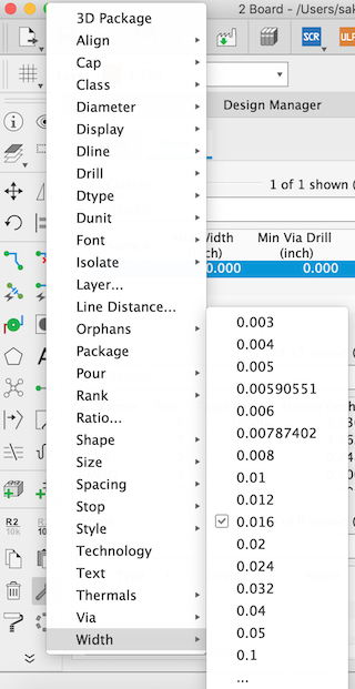
Setting line width
-
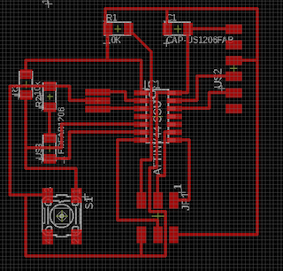
connected all compornents
-
-
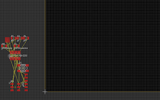
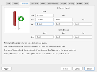
Drew lines and checked design with hitting “drc” command
-
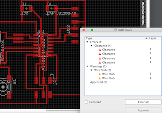
There was clealance error. So I widen the margin between lines.
-
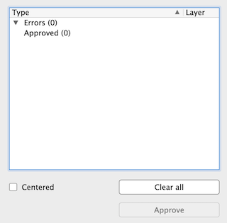
cleared all error
-
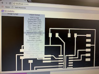
export circuit as .png image
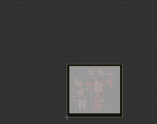
-
filtered only Top
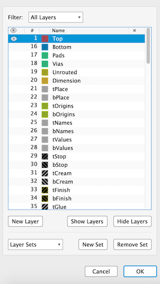
-
export
-
also exported outline
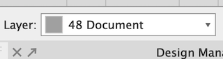
-
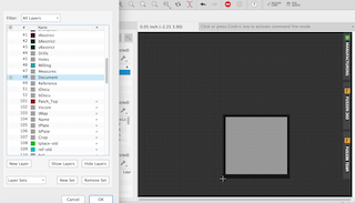
filterd only document
-
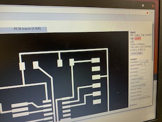
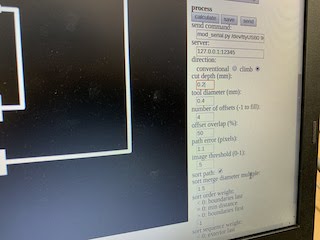
Made a file for mill by using FabModules
-
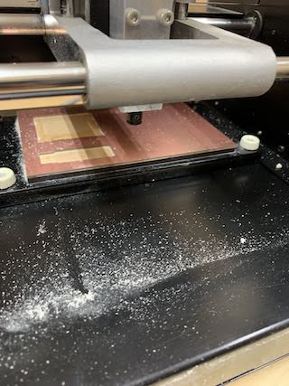
Milled with MDX-15
-
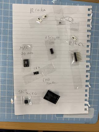
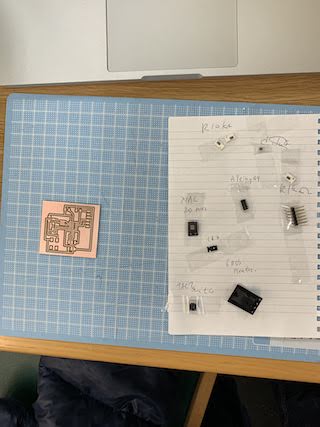
Parts and milled board
-
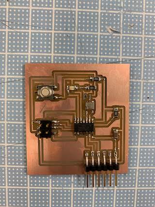
Solderd parts
-
Making connector cable
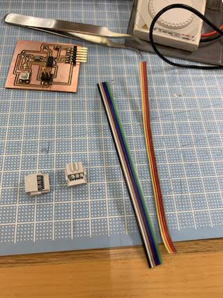
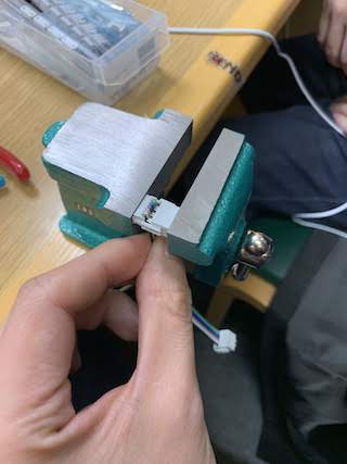
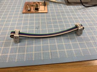
-
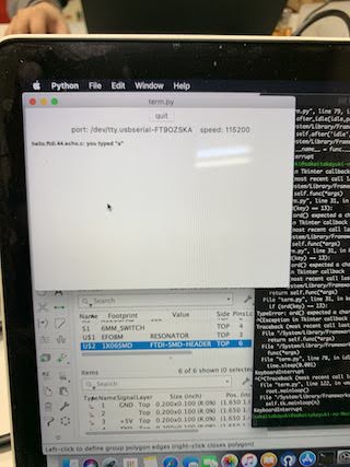
conneceted and write term.py through FabISP
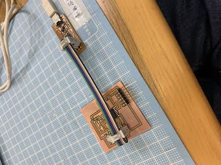
-
term.py is working!
Parts
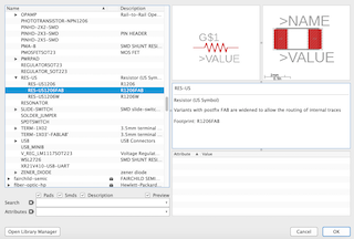
- Resistance 10k ohm
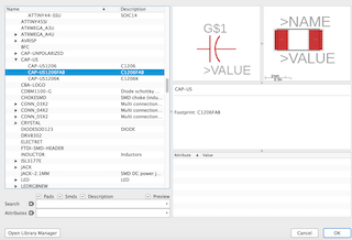
- Capacitor 1uF
- Attiny 44
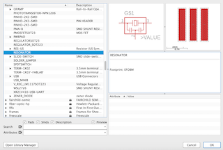
- Resonator 20MHz
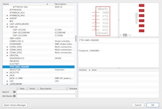
- Pin header 2x3
-
Pin header 1X6
-
Switch
- LED
- Resistance 1k ohm
- Resistance 10k ohm