Input Devices
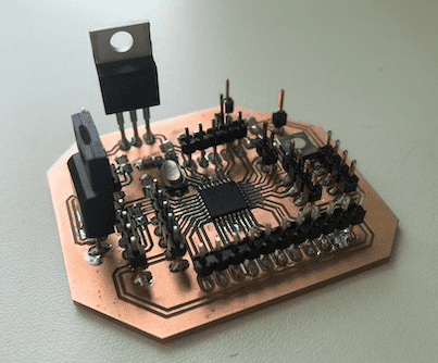
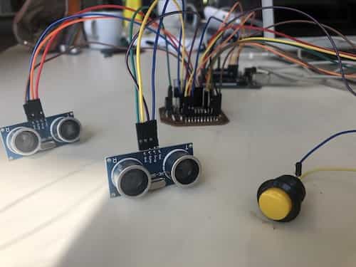
For this week's assignment we had to measure something by adding a sensor to a self-designed microcontroller board and read it's values. I decided to mill a new PCB, since the one I made in the Electronics Design week was far too precious. The purpose was to create a board for the Foosball Table, which indicated if someone had made a goal. In order to make the board recognize this I used a Ultrasonic Sonar Sensor.
Group Assignment
For this week's group assignment we had to probe an input device's analog levels and digital signals. You can find the documentaion here.
Ultrasonic Sonar Sensor
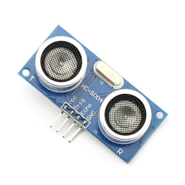
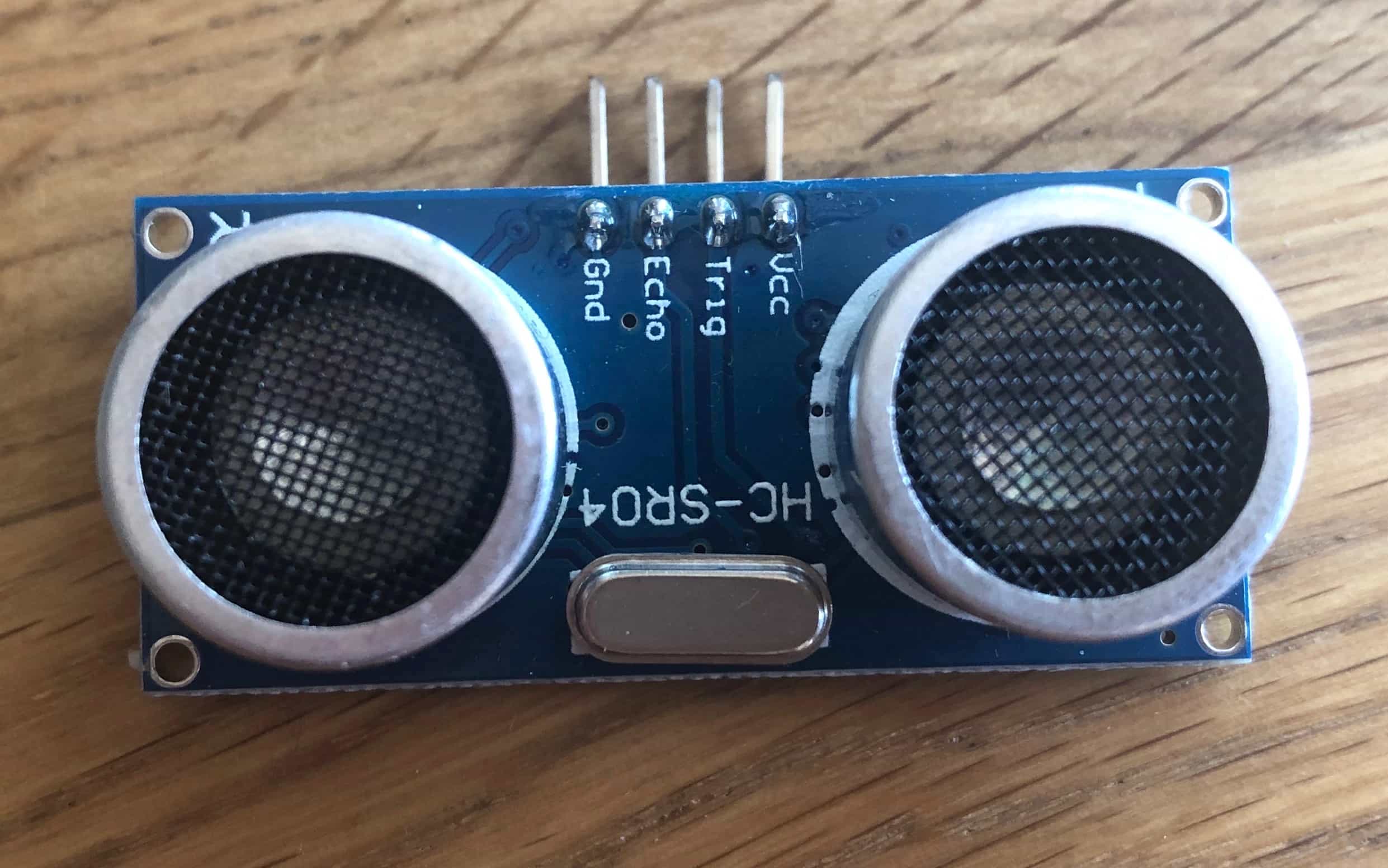
The HC-SR04 Ultrasonic Sensor uses sonar to determine the distance to an object. Each time the sound reflects back after striking with a surface it detects it's distance. The sound waves are at a frequency too high for humans to hear. To do this it uses a so called Tring Pin and a Echo Pin. The transmitter is the Trig Pin it sends the signal. As soon as the signal finds an object, it is reflected and the Echo Pin receives it.
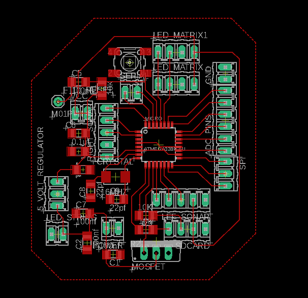
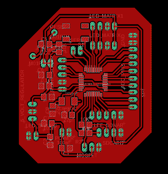
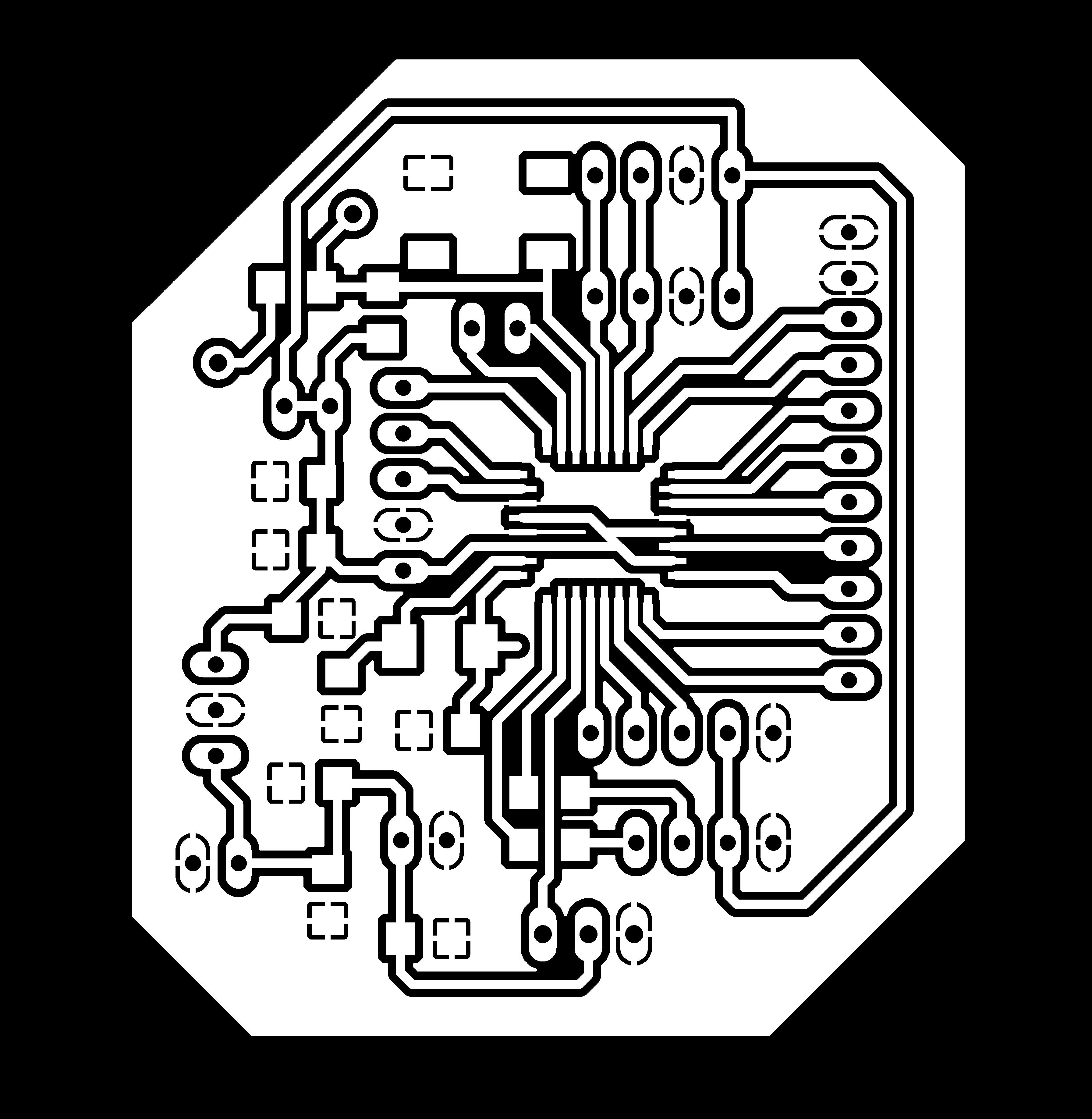
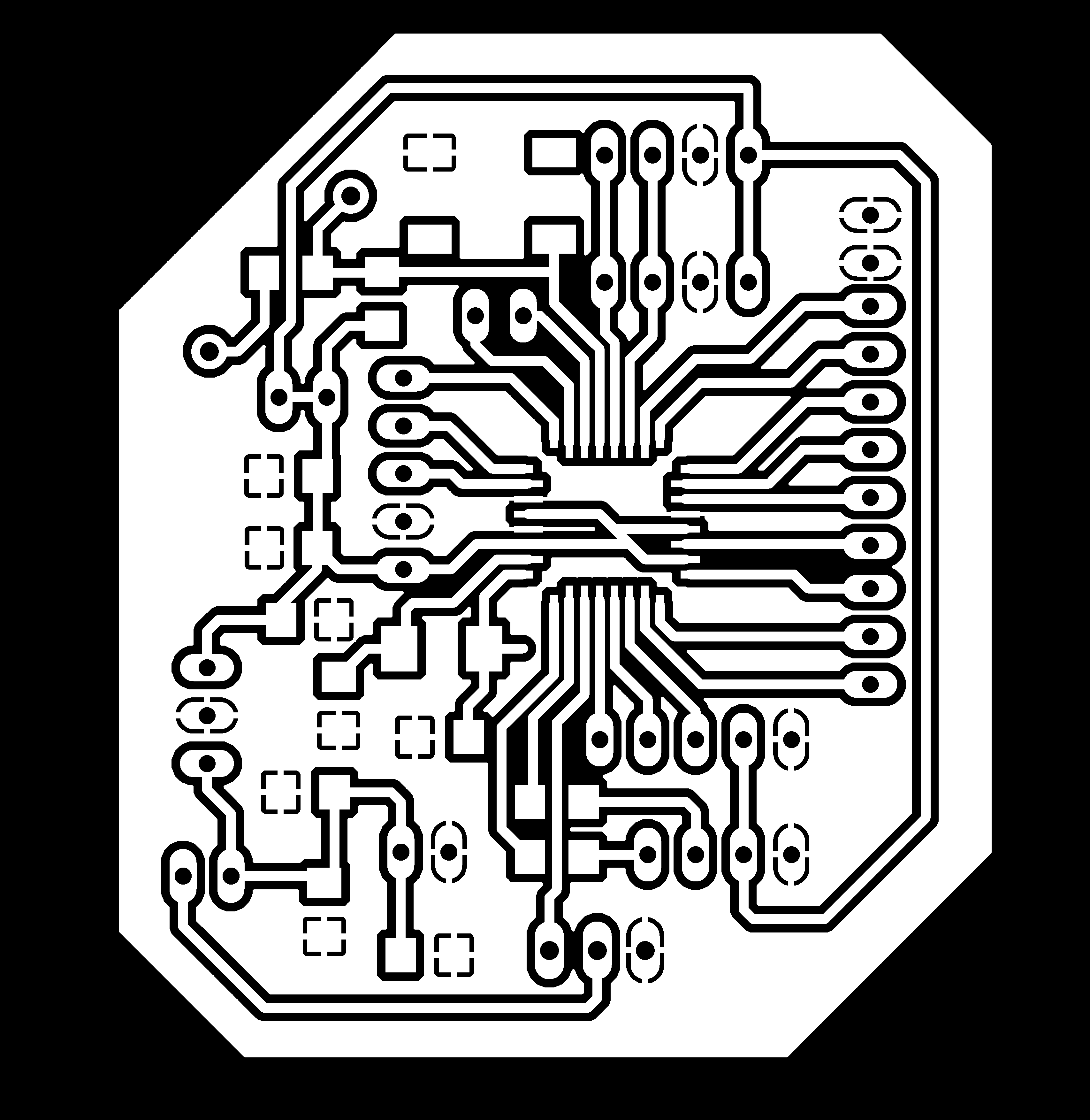
Schematic & Board Layout
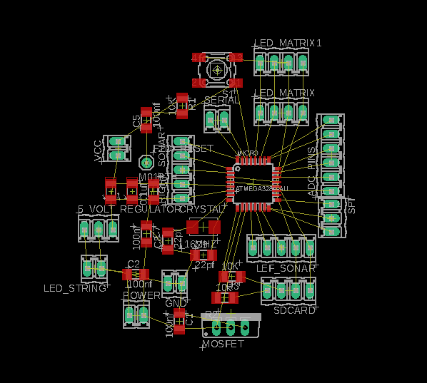
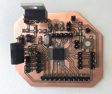
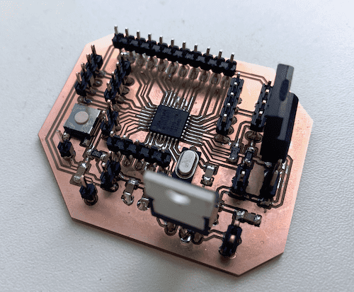
As microcontroller I decided to use a ATmega328PB, wich is similar to the microcontroller used for the Arduino Uno. Moreover I also thought about the Output Devices assignment of the upcomming week. That's why I already added pins for the output devices. To display the score of the game I wanted to use two 8x8 LED-Matrix Displays. In addition I also planned on using two speakers to let a crowd cheer or play a song as soon as someone scored. To transmit the song to the speakers I plan on using a Micro SD card reader. For more details go to the Output Devices assignment. To get a full introduction on how to make a Schematic and Board Layout with Eagle go to the Electronics Design week.
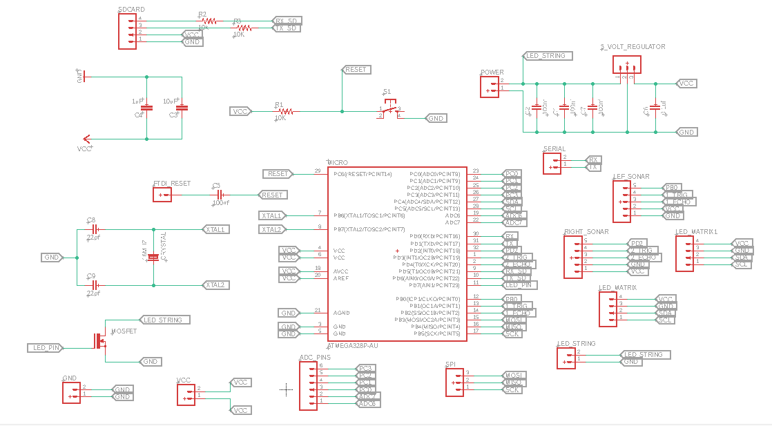
Futhermore I also had in mind to attach a LED string around the foosball table. This I had to consider beforehand, because the LED's are powered at 12V and the PCB at 5V. Therefore I had to add a Voltage Regulator and a Mosfet to my circuitry.
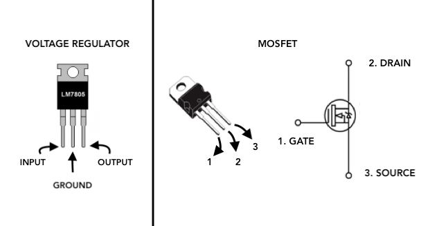
A voltage regulator simply takes a voltage that is too high, and reduces it down to a set voltage in this case 5V. I used the LM7805 Voltage Regulator it has a fixed output voltage of 5V. Always consult the datasheet to see how to hook it up with the necessary required external components. For the LM7805 Voltage Regulator a 0.33uF capacitor is required after the voltage source, in this case the 12-volt power supply and before the input pin of the LM7805 regulator. This capacitor filters out any noise coming from the voltage source. The voltage regulator works best and will be most efficient when a clean DC signal is fed into it. The second capacito is the 0.1uF capacitor, placed after the voltage regulator. This capacitor also filters out any noise or high-frequency signals that may be on the DC voltage line.
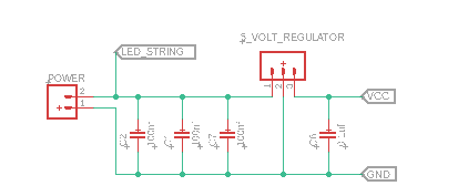
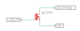
A Mosfet is a special type of field-effect transistor (FET). You may think of it as a variable resistor, where the gate-source voltage difference can control the drain-source Resistance. When there is no applying voltage between the gate-source, the drain-source resistance is very high, so no current is flowing through the drain, which means it acts kind like an open circuit. When voltage is applied, the drain-source resistance is reduced and there will be current flowing though the drain, which means it's now a closed circuit. I am using the IRL22 Mosfet, which is an N-channel Mosfet. Here the source is connected to the ground, the drain to the negativ load (negative load of the LED String) , and the FET will turn on when a positive voltage is applied to the gate (pin of the microcontroller).
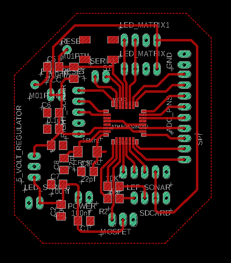
Next I started creating the board Layout.
Since the PCB had a lot of components I decide to make a GND Layer. To do this you have to select the Polygon tool in the toolbar.
Next draw a border line and make sure that you close it properly. Then a window will appear asking to name the border line. Type in GND, since it's going to be a GND Layer.
Then increase the thickness of the traces by opening the Run ULP window.
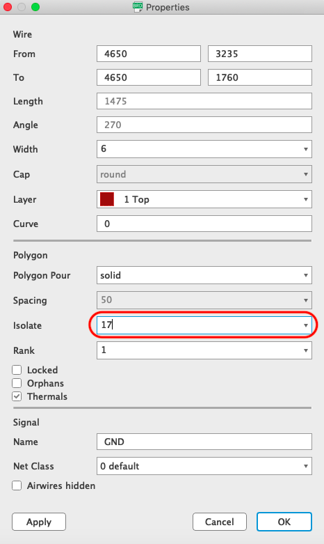
Now you have to set the isolation value between the GND Layer and the traces. To do this right click on the border line and open it's properties.
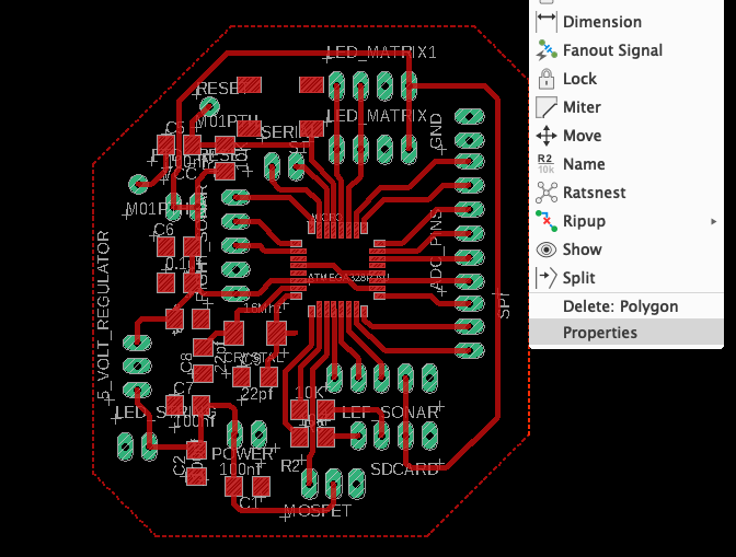
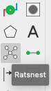
To see if you have the right isolation value, select the Rastnets tool and the designed GND Layer will appear.
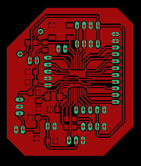
Finally get rid of all the unnecessary details.
Now export the file as an image.
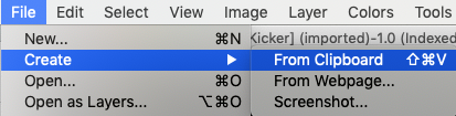
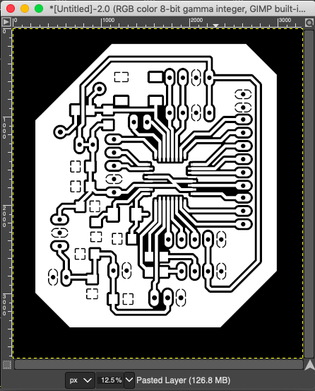
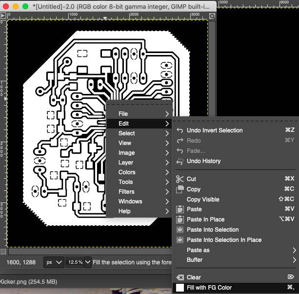
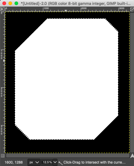
Before you generate the G-Code you have to make some modifications on the image. Therefore import it into a Image Editor such as Gimp. The goal is to create an inside and an outside Board Layout, since the process is made out of two different operations with the CNC Machine. Select the rectangle tool to create the image, which mills the circuit.

And Then cropp the image to create it from clipboard.
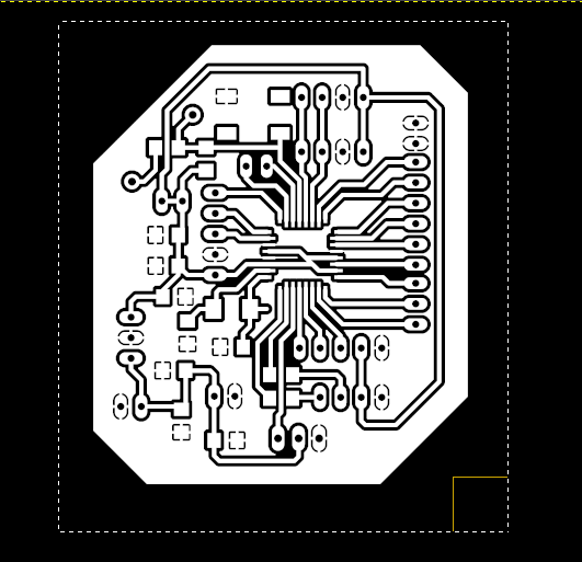
Export this image as PNG.
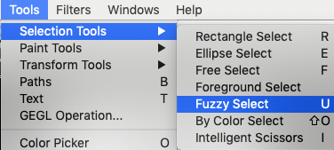
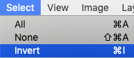
Next you have to create the image to remove the board from the copper plate. Select Fuzzy Select and then invert the selection to color the inside of the board.
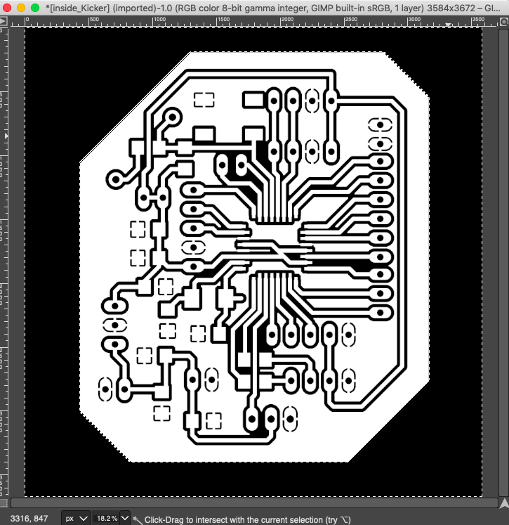
Export the image as PNG.
With these files you generate G-Code. To prepare the G-Code I used the Fab Modules software, as I did in the Electronics Production week. There you can read more about how to use the software.

Milling & Soldering
After generating the G-Code for the Roland Mill I started the job. To read more about how to generate the G-Code and how to use the Roland Mill go visit the Electronics Production page.
Unfortunately, I screwed up a connection. I connected the load to the positive load of the LED string, but fortunately I could simply repair it by trimming the trace and replacing the capacitor with a pin header.
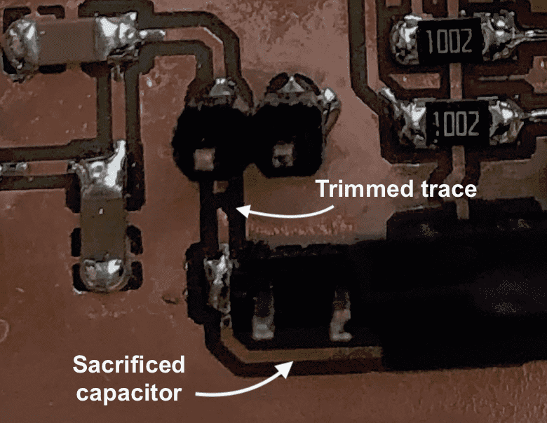
Underneath you can find the modified circuitry.
Programming
I am using an Arduino Uno to programm my PCB. To do this you have to upload the ISP sketch on the Arduino Uno. If you want to know more about it, go to the Electronics Production assignment.
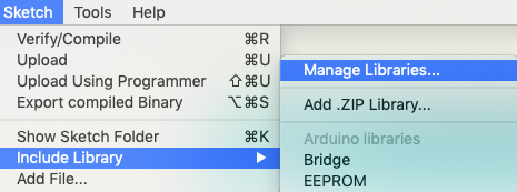
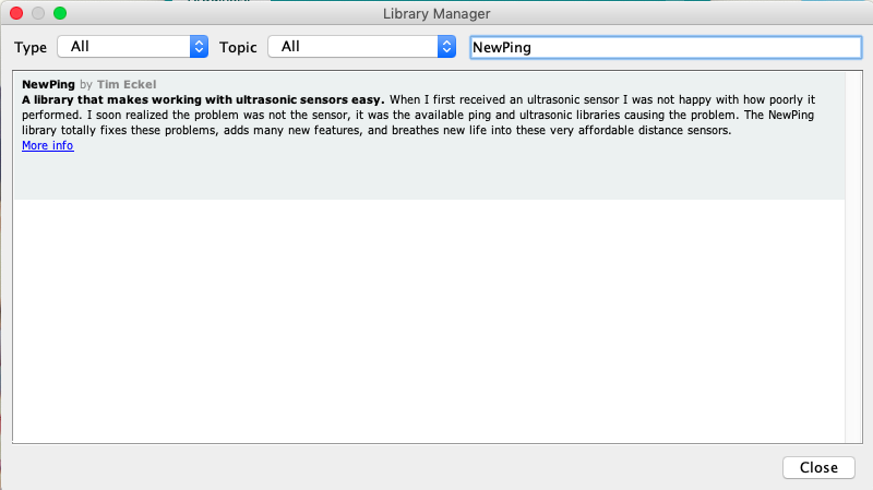
For this assignment I had to add a library t my code. To do this go to Sketch -> Include Library -> Manage Labraries.
Then enter the name of the library you are looking for and install it. In addition you could also download a library from the Internet and add it to the arduino library folder.
Underneath you can find the code I wrote. It detects the values of the two ultrasonic sonar sensors. Each time the value is less than 9, one of the teams scored a goal. Moreover I also decided to add a button interrupt the game when someone scored a goal. The serial output is stopped and only restarted when you press the button.
// libraries included
#include <Wire.h>
#include <NewPing.h>

//decleares two digital Pins as Trig and Echo
#define trig 3
#define echo 4
#define max_distance 8
#define trigPin 9
#define echoPin 10
#define buttonPin 2

// NewPing setup of pins and maximum distance
NewPing sonar(trig, echo, max_distance);

// defines variables
long duration;
int distance;
int spacing;
boolean flag = true;
int buttonState = 0;
int red_score = 0;
int blue_score = 0;


void setup() {
pinMode(trigPin, OUTPUT); // Sets the trigPin as an Output
pinMode(echoPin, INPUT); // Sets the echoPin as an Input
pinMode(buttonPin, INPUT_PULLUP);	// the button is connected to a internal pullup pin so it's always set to HIGH
Serial.begin(9600); // Starts the serial communication
}

void loop() {
  //reads the Buttonstate 0 = LOW 1 = HIGH
  buttonState = digitalRead(buttonPin);
  // prints the Buttonstate, I only use it to check if the Button works
  //Serial.println(buttonState);
  Sonar();
  Sonar_using_Lib();
  // if the Button gets pressed, change the value of the flag and restart the game
  if (buttonState == LOW) {
    flag = true;
  }
}

void Sonar () {
  // Clears the trigPin
digitalWrite(trigPin, LOW);
delayMicroseconds(2);
// Sets the trigPin on HIGH state for 10 micro seconds
digitalWrite(trigPin, HIGH);
delayMicroseconds(10);
digitalWrite(trigPin, LOW);
// Reads the echoPin, returns the sound wave travel time in microseconds
duration = pulseIn(echoPin, HIGH);
// Calculating the distance
distance= duration*0.034/2;
// Prints the distance on the Serial Monitor only if the flag is true
if (flag == true ) {
Serial.print("Distance of Team Red: ");
Serial.print(distance);
Serial.println("cm");
// If the value is between 0 - 8 a Goal has been made
if (distance <9 && distance > 0) {
  //counts the score
  red_score = red_score +1;
  Serial.println(" GOAL !!! FOR TEAM RED");
  Serial.println("Score: Team Blue | Team Red");
  Serial.print(blue_score);
  Serial.print(" | ");
  Serial.println(red_score);
  // stops the output on the serial to reset it (to restart the game) push the button
  flag = false;
  delay(100);
    }
  }
}

void Sonar_using_Lib() {
delay(50);
spacing = sonar.ping_cm();
// Prints the distance on the Serial Monitor only if the flag is true
if (flag == true) {
Serial.print("Distance of Team Blue: " );
Serial.print(spacing);
Serial.println("cm");
// If the value is between 0 - 8 a Goal has been made
if (spacing <9 && spacing > 0) {
  //counts the score
  blue_score = blue_score +1;
  Serial.println(" GOAL !!! FOR TEAM BLUE");
  Serial.println("Score: Team Blue | Team Red");
  Serial.print(blue_score);
  Serial.print(" | ");
  Serial.println(red_score);
  delay(100);
  // stops the output on the serial to reset it (to restart the game) push the button
  flag = false;
    }
  }
}