Networking and Communications
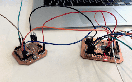
For this week's assignment the goal was to design, build, and connect wired or wireless node(s) with network or bus addresses. To complete this task I decided to design and mill two new boards. With these two boards I wanted to test whether it is possible to drive the electric Go-Kart automatically. So I am going to use two brushless Motors and a Joystick to drive the Kart. The board that sends the values of the joystick will be the master and the other the slave that drives the motor according to the values.
Group Assignment
For this week's group assignment we had to send a message between two projects. You can find the documentaion here.
Brushless Motor & Joystick
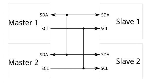
The idea was to work on a code for my final project, since the idea was to have a automatic steering. I wanted to build two boards and communicate via I2C. I2C is a serial protocol for two-wire interface to connect low-speed devices like microcontrollers, EEPROMs, A/D and D/A converters, I/O interfaces and other similar peripherals in embedded systems. The I2C bus is a very popular and powerful bus used for communication between a master (or multiple masters) and a single or multiple slave devices. Each I2C slave device needs an address. I2C uses only two wires: SCL (serial clock) and SDA (serial data).
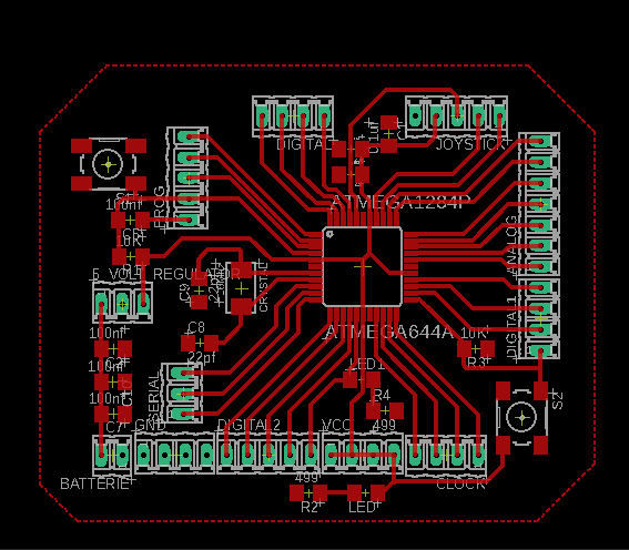
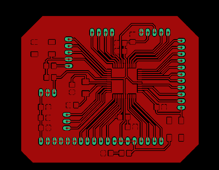
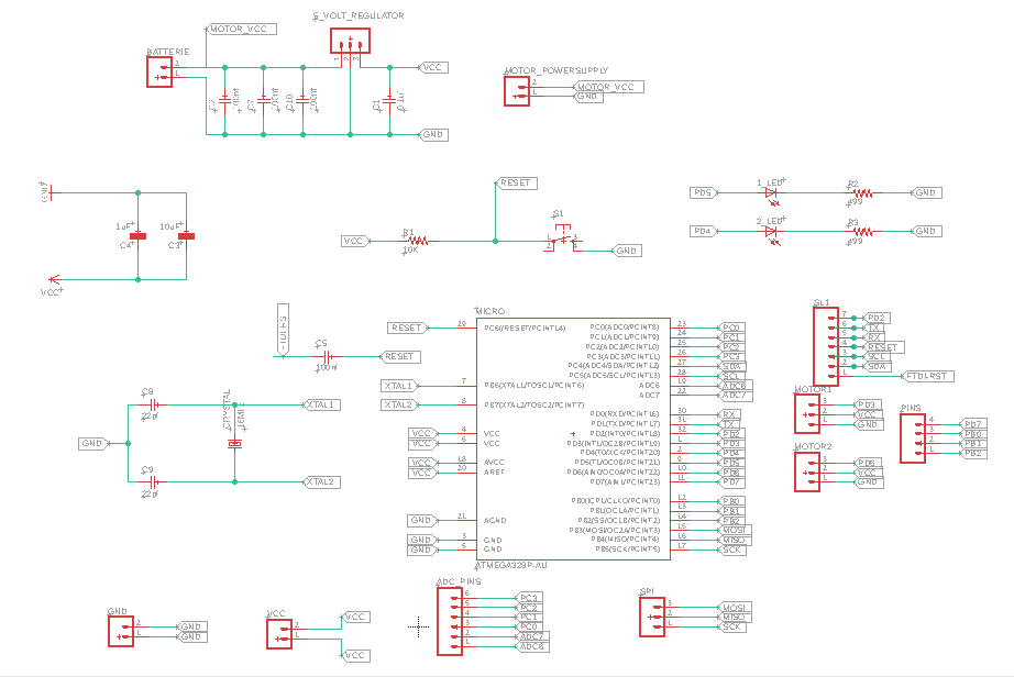
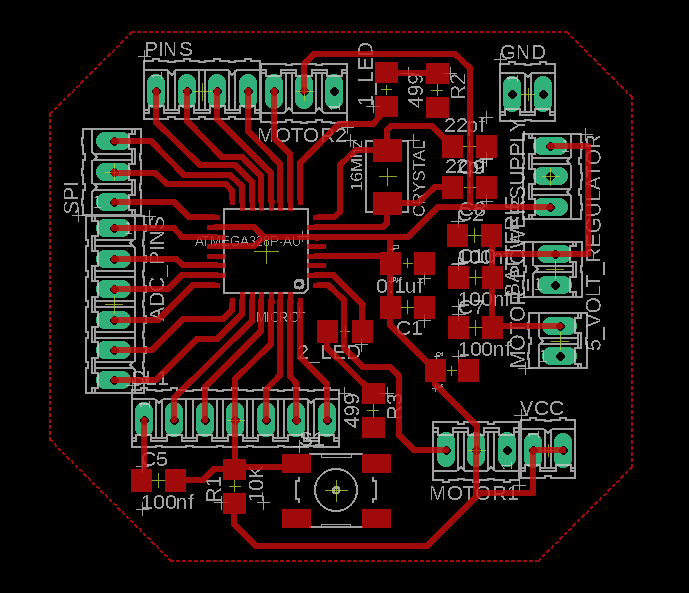
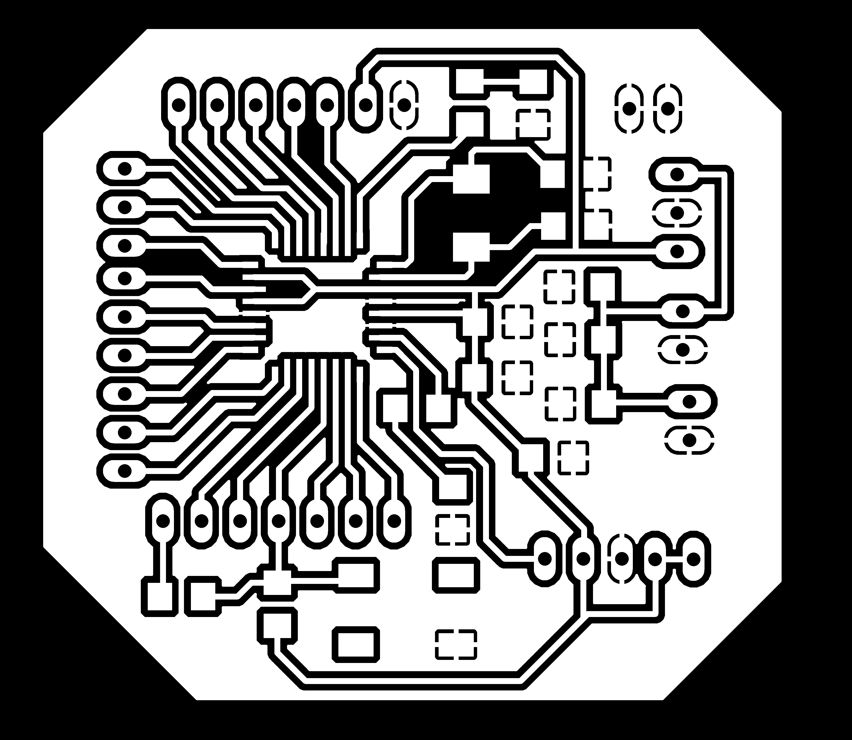
Schematic & Board Layout
To get a full introduction on how to make a Schematic and Board Layout with Eagle go to the Electronics Design week.
Master Board
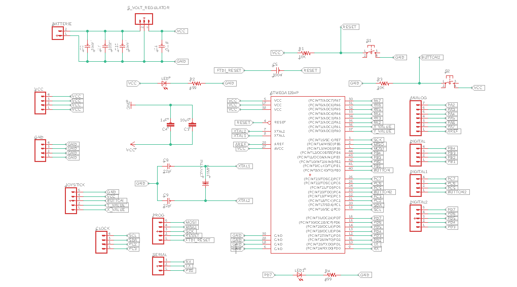
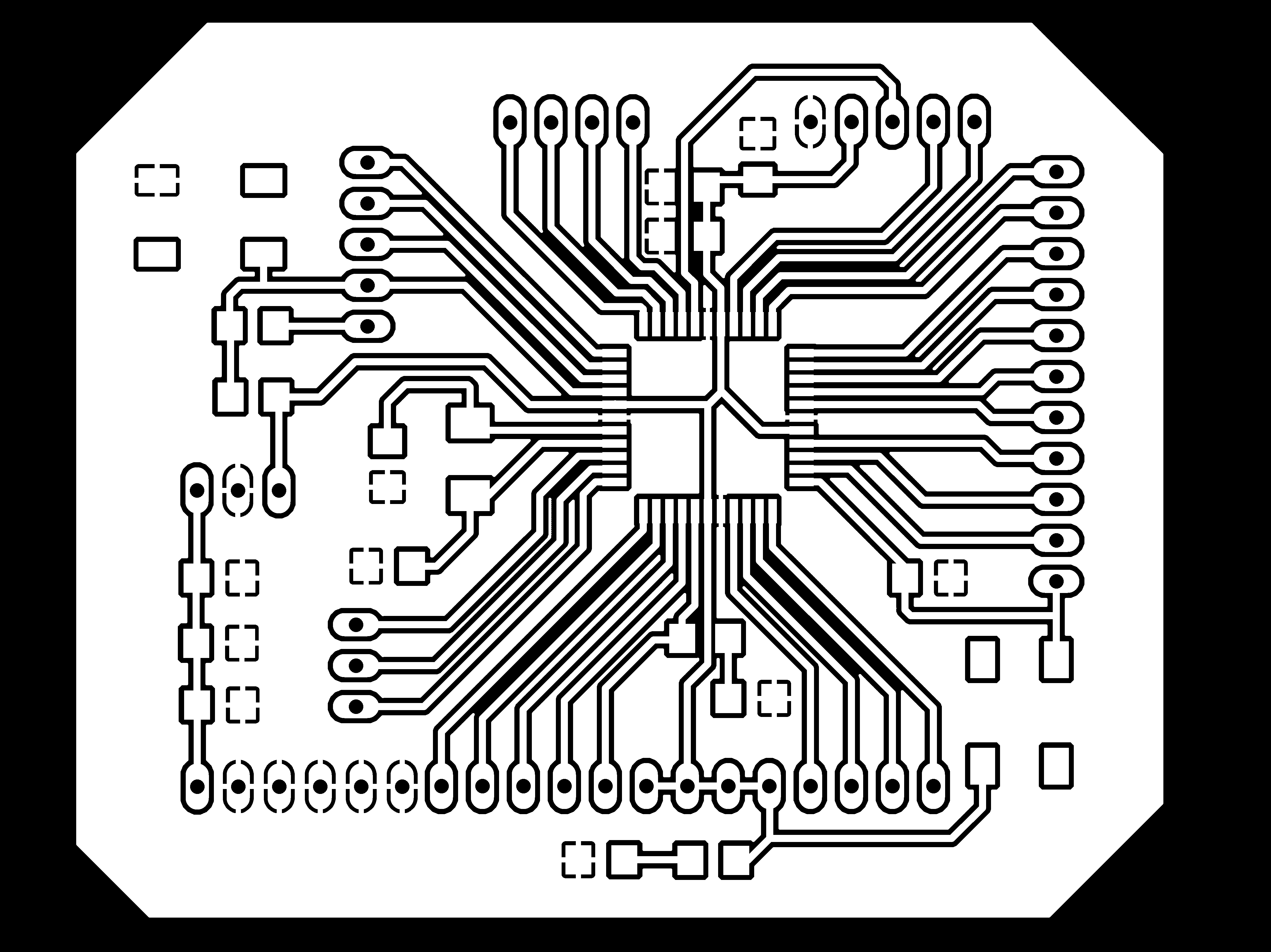

Slave Board
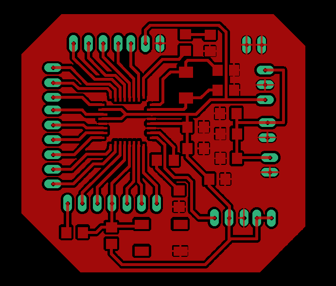

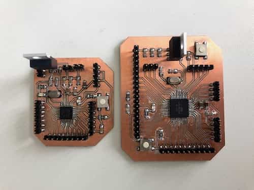
Milling & Soldering
After generating the G-Code for the Roland Mill I started the job. To read more about how to generate the G-Code and how to use the Roland Mill go visit the Electronics Production page.
Programming
Master Code:
The master code maps the values of the joystick to the values of the brushless motor and then sends them to the slave board.
#include <Wire.h>

#define LED 15 // define the LED pin
const byte X_value  = A0;   // X input connected to A0
const byte Y_value  = A1;   // Y input connected to A1
const byte Button_Pin = 2;    // pushbuttom input connected to Digital pin 7

byte input = 0;

// joystick value
byte sensorValuex,sensorValuey, buttonState;

void setup() {
	Wire.begin();  // join i2c bus (address optional for master)
	Serial.begin(9600); //here we declare Serial at 9600 baudrate for the input
	pinMode(LED, OUTPUT);  // set LED pin as an output
	pinMode (Button_Pin, INPUT_PULLUP); // internal pull up resistor
    pinMode (X_value, INPUT);  // initialize Xin as INPUT
    pinMode (Y_value, INPUT);  // initialize YZin as INPUT
}

void loop() {
readJoystick();
}

void readJoystick(){
//Serial.println (analogRead(X_value));
input= map(analogRead(X_value), 0, 1023, 0, 180); //Map the input values from the joystick on analog pin 0 to  correspond to max and min values for the servo output: 180 and 0

// send the sensor Value of x through radio
Wire.beginTransmission(11); // transmit to device 1
Wire.write(input);
Wire.endTransmission();    // stop transmitting
Serial.println(input);
delay(50);
}
Slave Code:
The slave board receives the mapped values from the master board to drive the motor.
#include <Wire.h>
#include <Servo.h>

#define LED 4

int servo_pin = 6;
int potentiometer ;

Servo myservo;  // create servo object to control a servo

void setup() {
	Wire.begin(11);
    Wire.onReceive(receiveEvent);
    pinMode(LED,OUTPUT); // set LED pin as an output
    Serial.begin(9600); //for debugging
    Serial.println("Initializing Servo"); //for debugging
    myservo.attach(servo_pin);
    Serial.println("Servo Begin");
    myservo.write(1023);
    delay(2000);
    Serial.println("You should hear a beeping sound ");
    myservo.write(534);
    delay(2000);
    myservo.write(53);
    Serial.println("The ESC will play a tone.");
    Serial.println("Reciever is ready");
    digitalWrite(LED, HIGH);   // turn the LED on (HIGH is the voltage level)
    delay(1000);    // wait for a second
    digitalWrite(LED, LOW);    // turn the LED off by making the voltage LOW
    delay(1000);
}

void loop() {
delay(100);
}

void receiveEvent () {
	while (0 < Wire.available()) { // the same thing as in serial
	potentiometer = Wire.read();
	Serial.println (potentiometer);
	//calibration the servos to the joystick
    myservo.write(2.85 * (potentiometer - 57));
    }
}
Download Files
Arduino Code
Master CodeSlave Code
PNG-Files
Master Slave PCBEagle-Files
Master Schematic & Board Layoutslave Schematic & Board Layout