Computer Controlled Cutting
The requirement for this week's assignment was to learn to work with the laser cutter and vinyl cutter. For the group assignment the goal was to characterize our laser cutter by making test part(s) with different cutting settings and dimensions. Moreover for the individual assignment we had to design, lasercut, and document a parametric press-fit construction kit, which could be assembled in multiple ways. At last we also had to cut something on the vinyl cutter.
Laser cutting techniques
Laser cutting is a technology that uses a laser to cut or engrave material based on computer-controlled parameters. The powerful and highly accurate laser focuses on a small area of the material. The laser can cut through different kinds of materials like: plastics, woods, rubbers, foams, papers, acrylics, fabrics and some even metal. With the laser cutter you have a total control of the beam of your laser when you use it. This means that you can control the beam heat output, the intensity of the beam on your material, and the duration of your beam. There are several techniques that can be performed with a laser cutter.
Group Assignment
For the documentation of the group assignment's we created a separate website. Click here to go to the documentation of this week's assignment.
Parametric Design
Making a parametric design allows you to modify it easily in cases where you might have to change the size of the model. It also gives the opportunity for anyone to replicate the design and use different dimensions. To create a parametric design I decided to use Autodesk Fusion 360, as I have allready worked with this software and really like it.
First of all I started designing a simple press-fit construction to learn how to create a parametric sketch. I used the line tool to create this simple design.
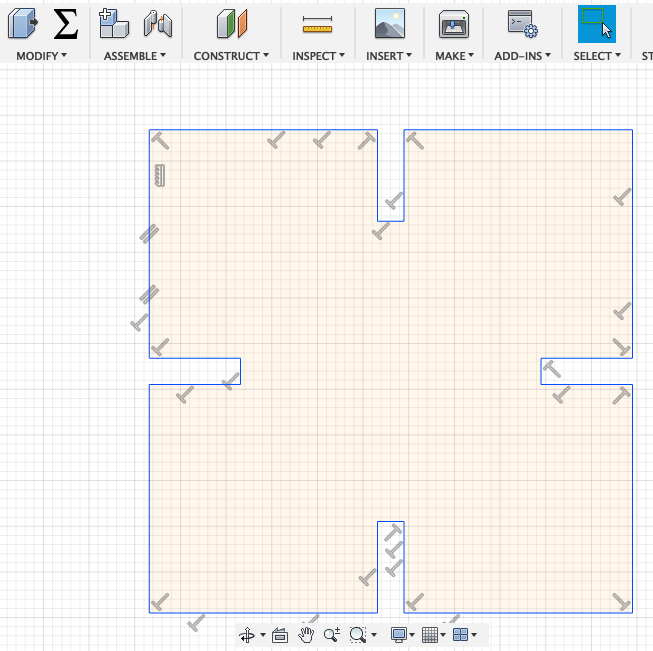
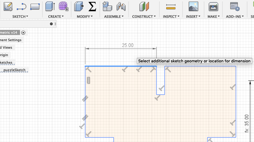
Afterwards I use the dimension tool. This tool shows you the exact length of the lines you create. Moreover you can also use it to change the length of the line by typing in a different value or parameter.
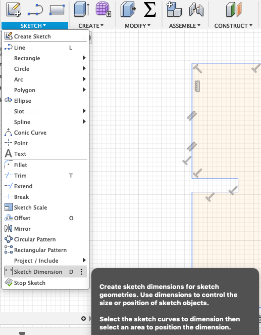
Select a line or two points to set the dimension.
Next you can start creating some parameters. Go to Modify --> Change Paramters.
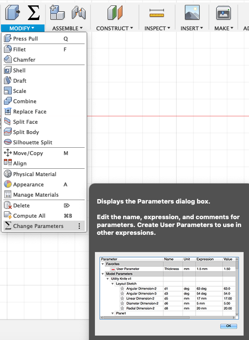
In the window that appears you will see all the parameters that I created and here you can also change them.
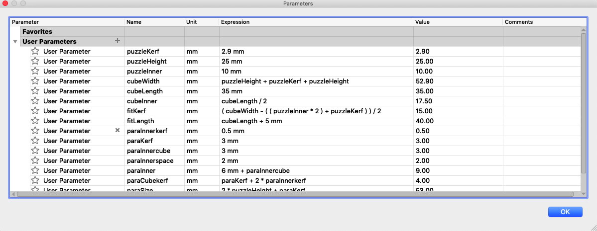
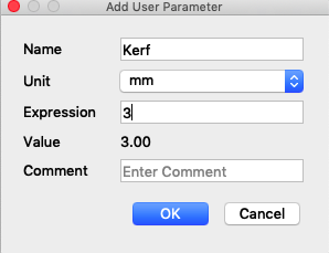
To create a parameter you have to enter a significant name and a value.
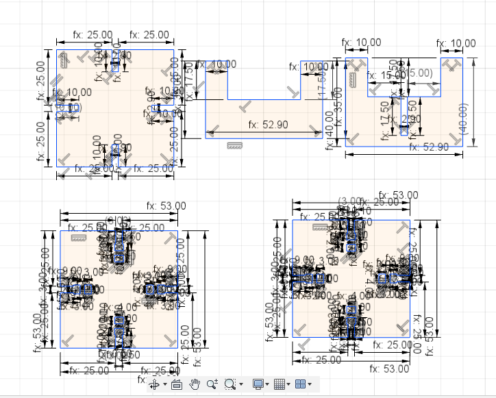
After creating the parameter you just have to assign it to the proper line. Moreover make sure that the lines in your design are straight, otherwise the model might get messed up after increasing or decreasing the values of the parameters.

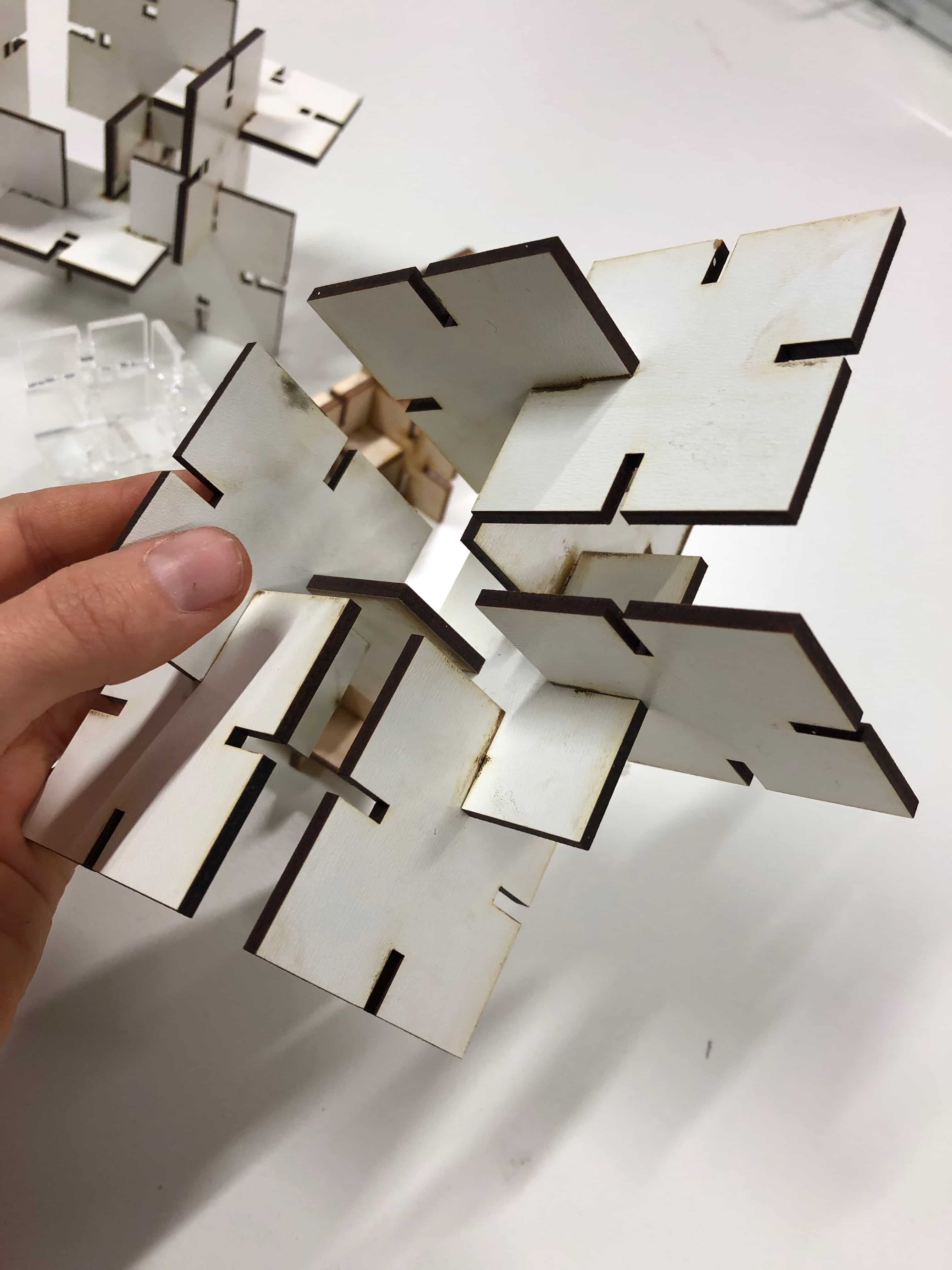
I especially liked the designs Neil showed in the video conference. So I wanted to create a similar one. The parametric software was really helpfull, because you can easily adjust the design to your desire. In this way I am able to change the slots for the fitting and to adjust them for different kind of materials.
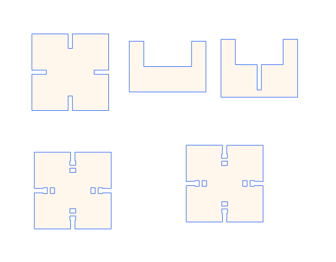
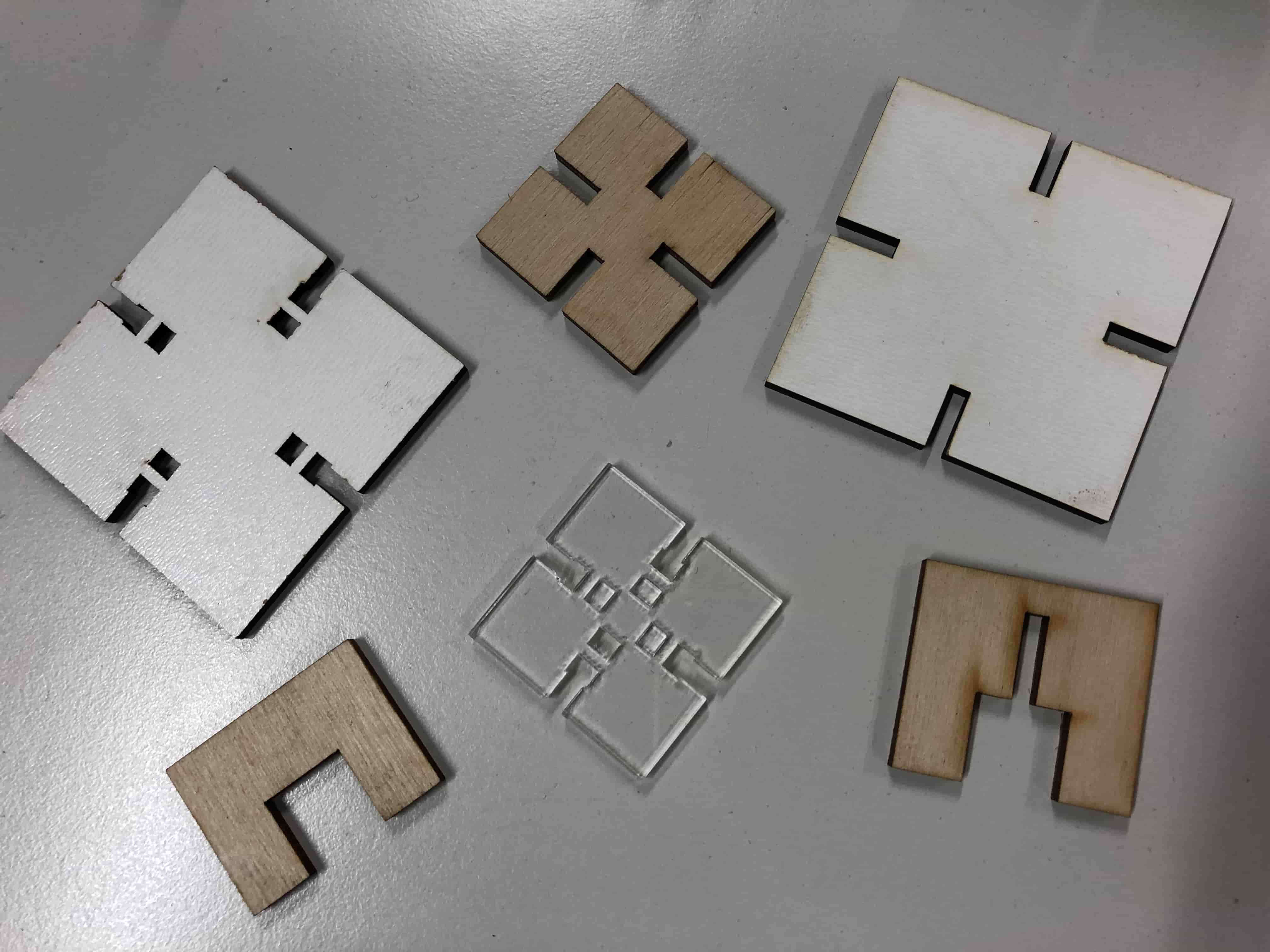
I also liked to experiment with different kind of joints. So first I created a very simple press-fit joint which you can find on the left side of the picture below. Then I wanted to create a jonit that consists of a grabbing function, which you can see at the bottom of the image. After you finished with your design you save the DXF-Files and go to the Laser Cutter.
Sending a Job
There are different softwares you can use to send a job to the machine such as Adobe Illustrator, Inkscape or Rhinoceros. I decided to use Rhinoceros. First of all your have to import your DXF file.
Then check if you have any double lines in your design. If everything looks good you can go ahead and join the lines (but if you still have double lines the join command won't work). Select everything and write join in the command line.
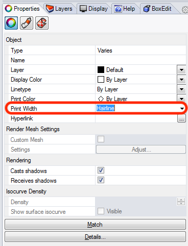
Next check under properties if the print width is set to hairline, otherwise the laser cutter won't recognize it as vector but as raster. This means it won't cut out but engrave the lines.
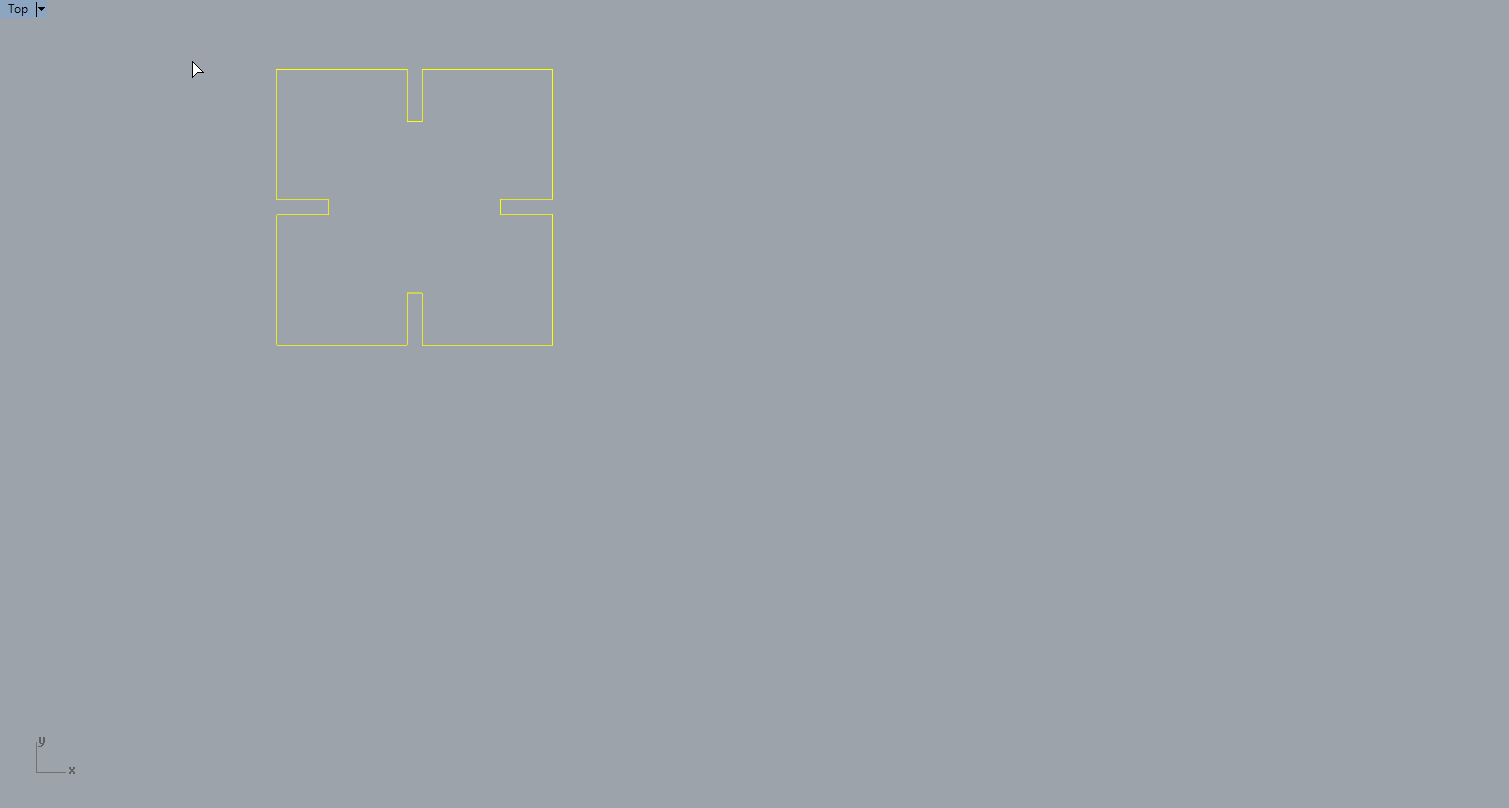
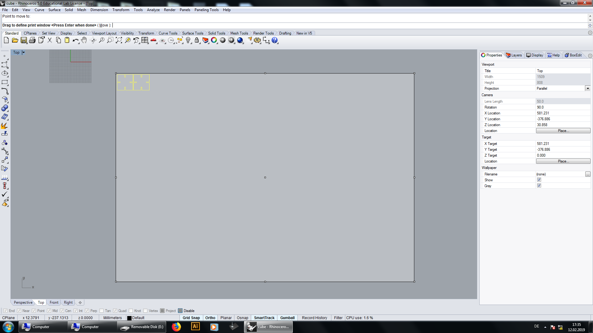
Now you can print the design. In the print profile you first have to set the proper window and always check if the scale is set to 1:1.
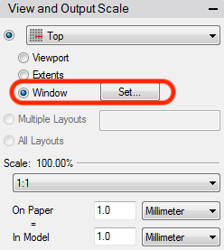
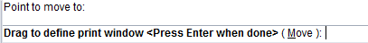
The start point of the laser cutter is in the left upper corner, so we have to set the window as near as possible to the design to don't waste a lot of material. Press enter and confirm the position of the window.
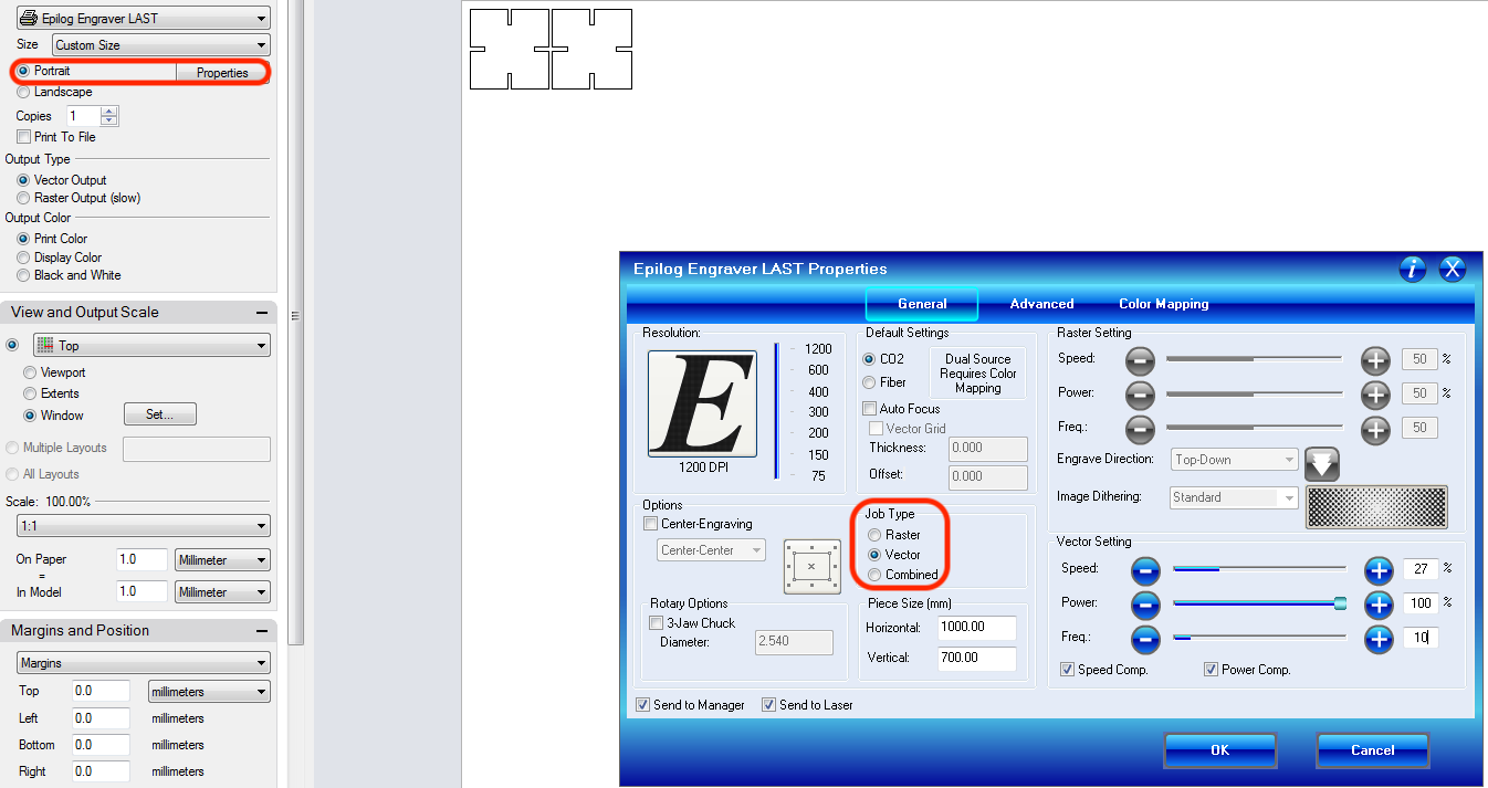
Finally you can set the properties for the laser. Since we want to cut out the pieces we select vector as job type. Now just set the vector settings (power, speed and frequency) and send the job.
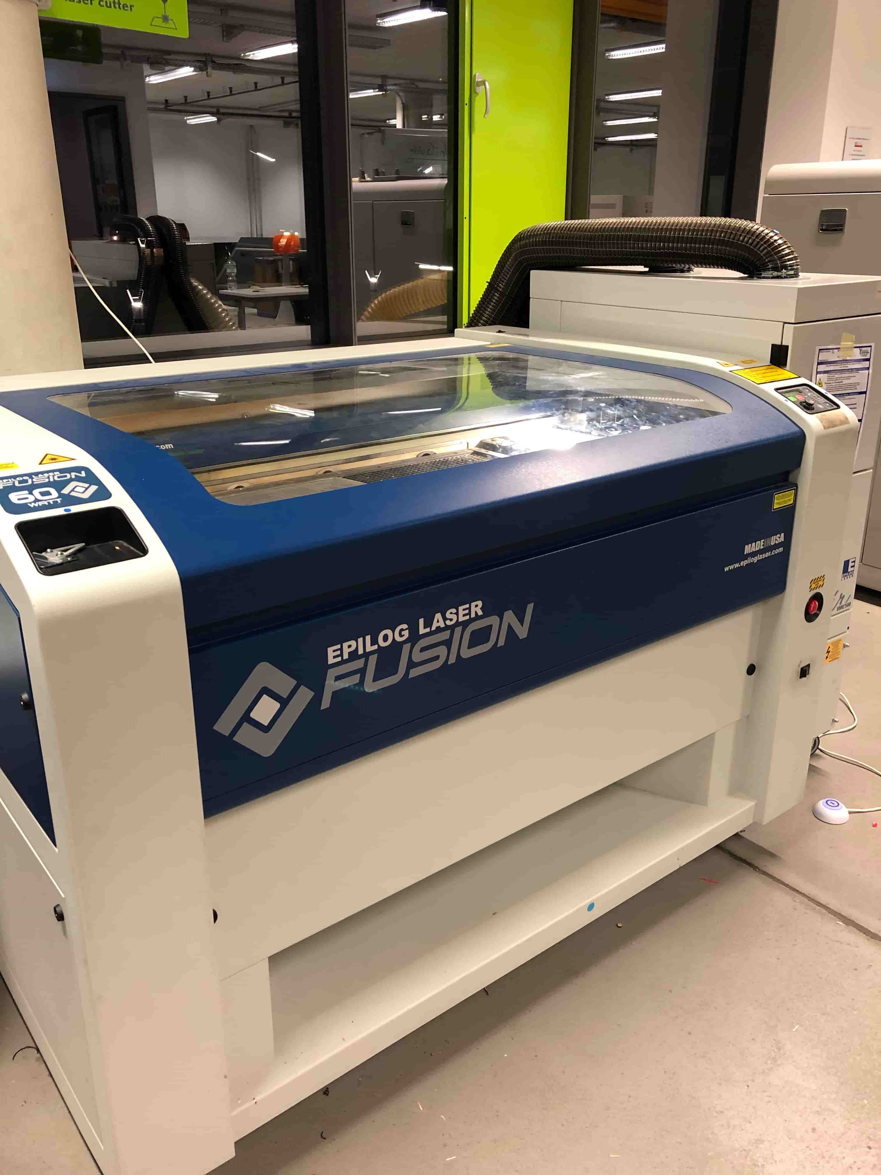
Using the Epilog Laser
Before you start the job there are some basic and very important rules that you have to follow:
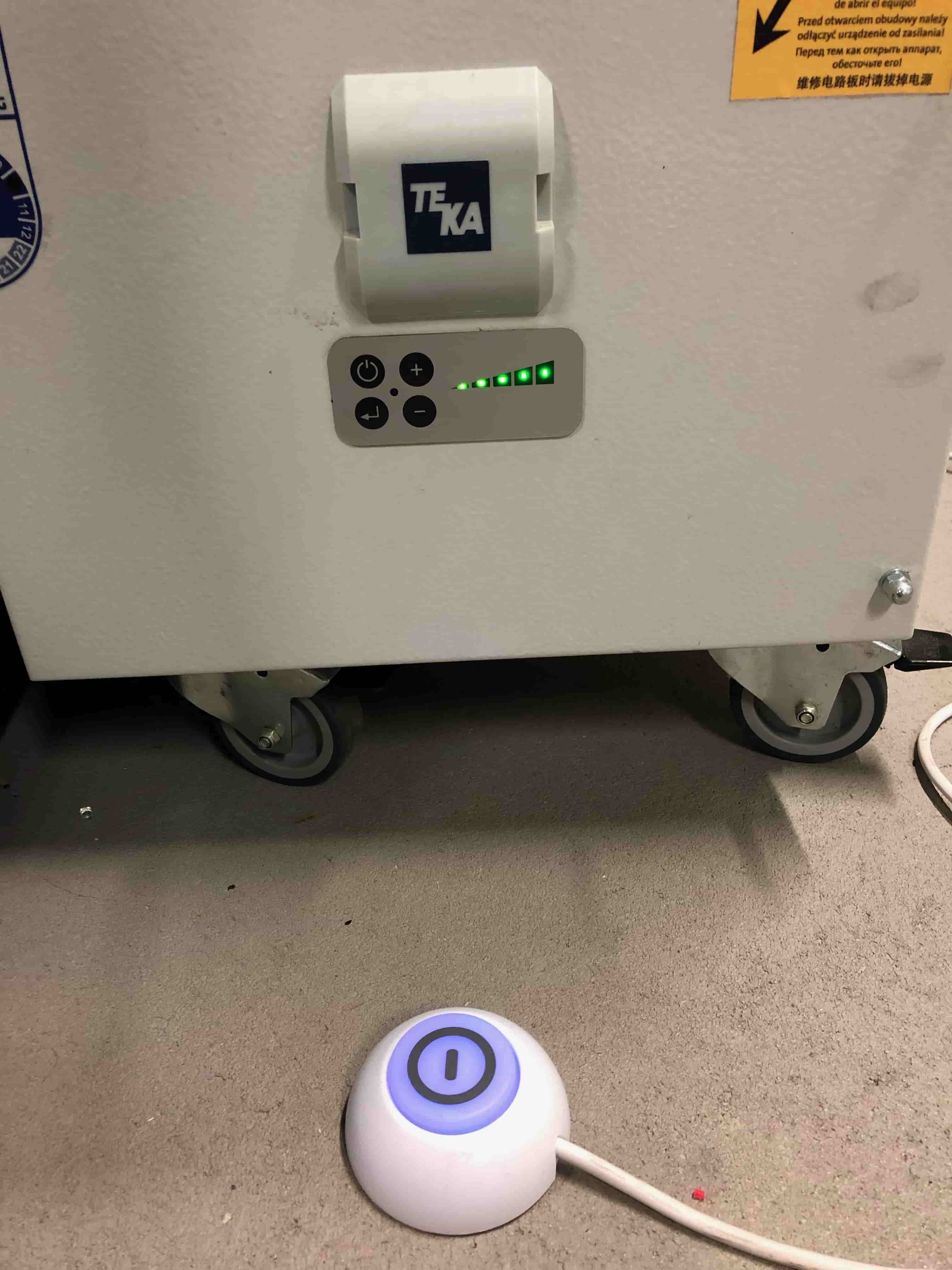
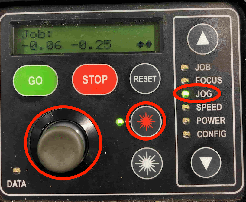
After we turn on the machine and the air compressor/filter, we have to set the focus and the jog before starting the job. First select the jog on the menu panel. Use the joystick to move the laser. Push the (star) lightning button, to activate the red laser pointer, which indicates where the job will start. After you move the jog to the right position, confirm it by pushing the joystick.
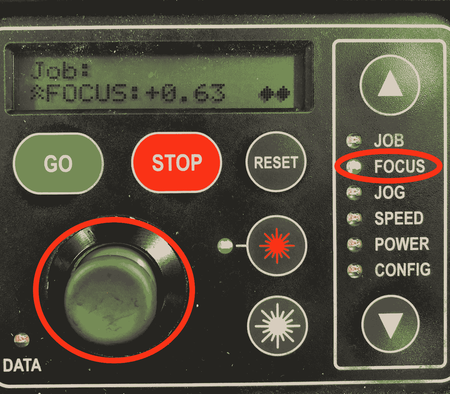
Now select the focus on the menu panel. Use the joystick to move the bed up and down. In addition use the triangle to measure the distance from the laser to the bed.
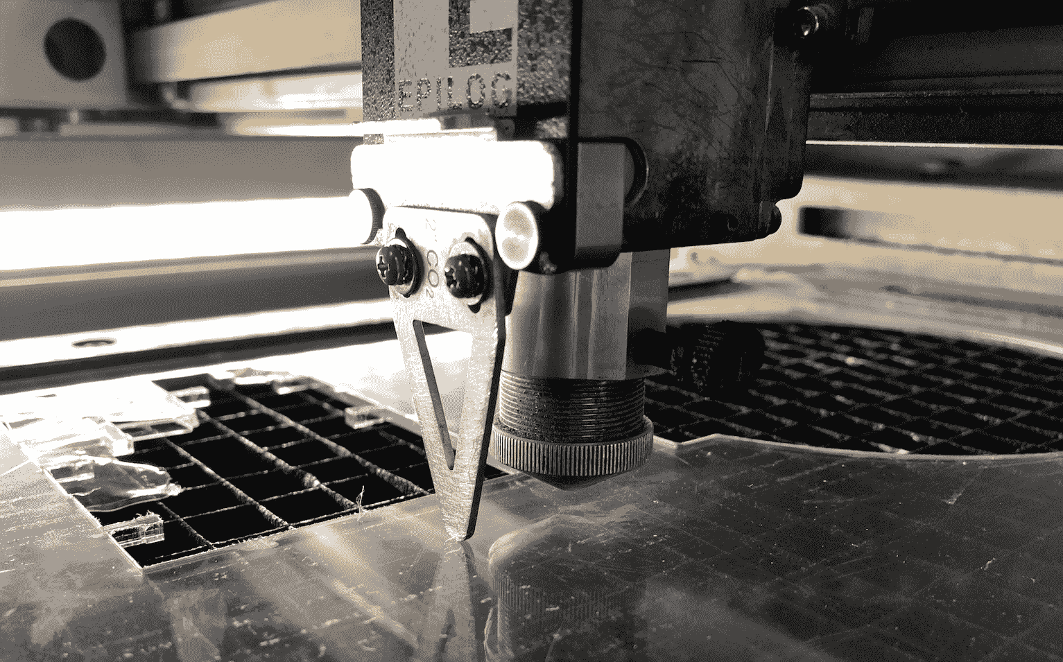
Hang the triangle on the designated place.
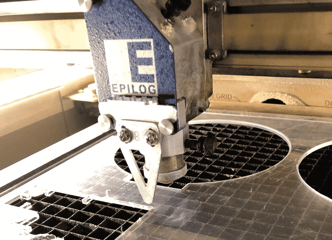
As soon as the traingle slightly touches the surface of the material, confirm your settings by pushing the joystick.
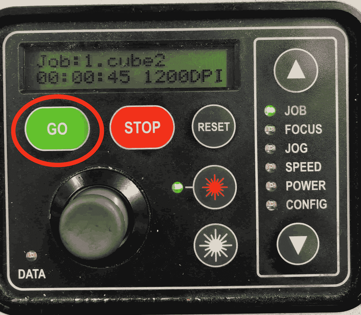
Since everything is set you can start the job. If you think you might have forgotten to confirm something, just push the reset button to check if everything will stay in the right position. On the display you can also see the duration and the file name of the job. Finally start the job.
Cutting the Designs
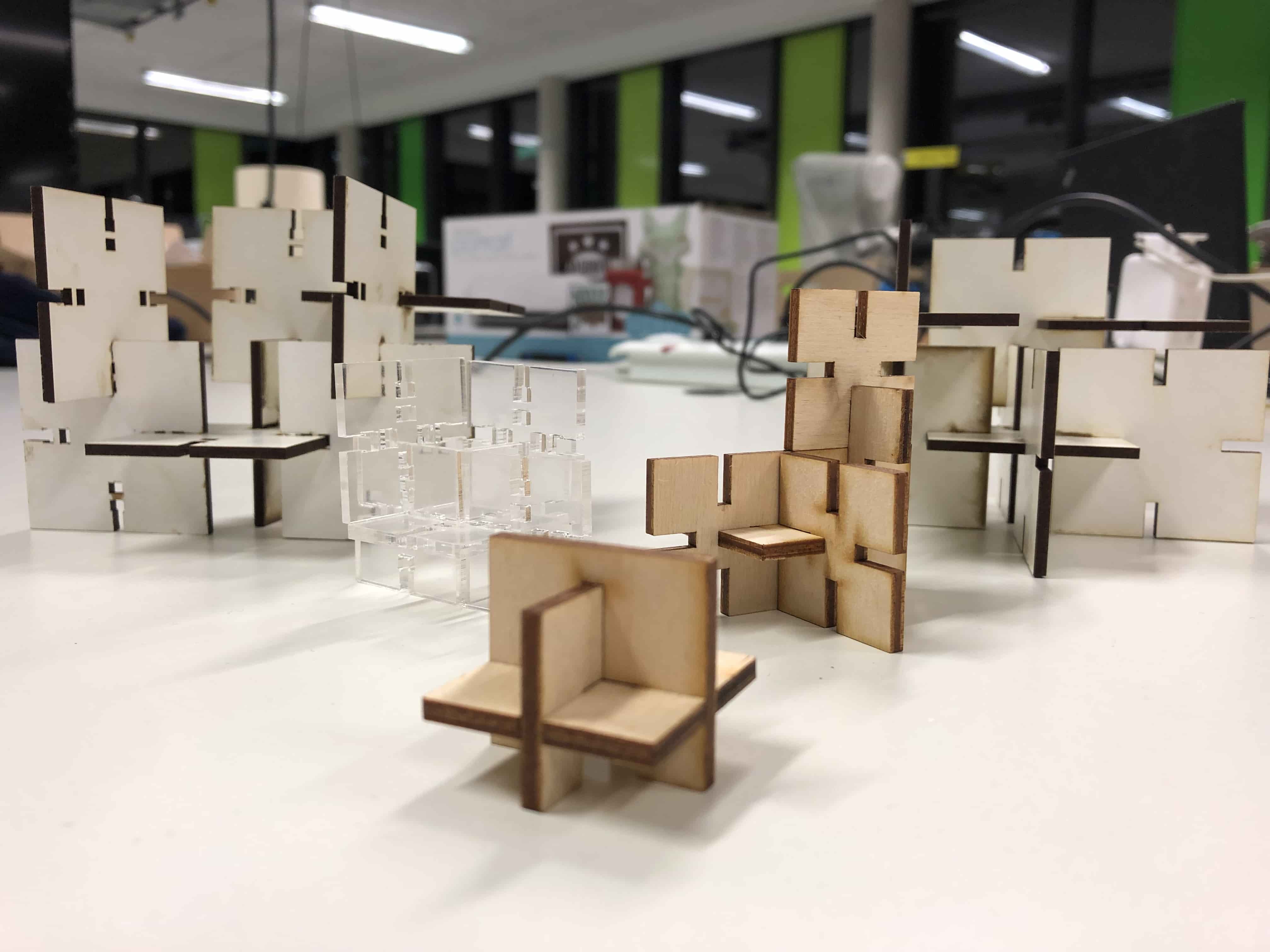
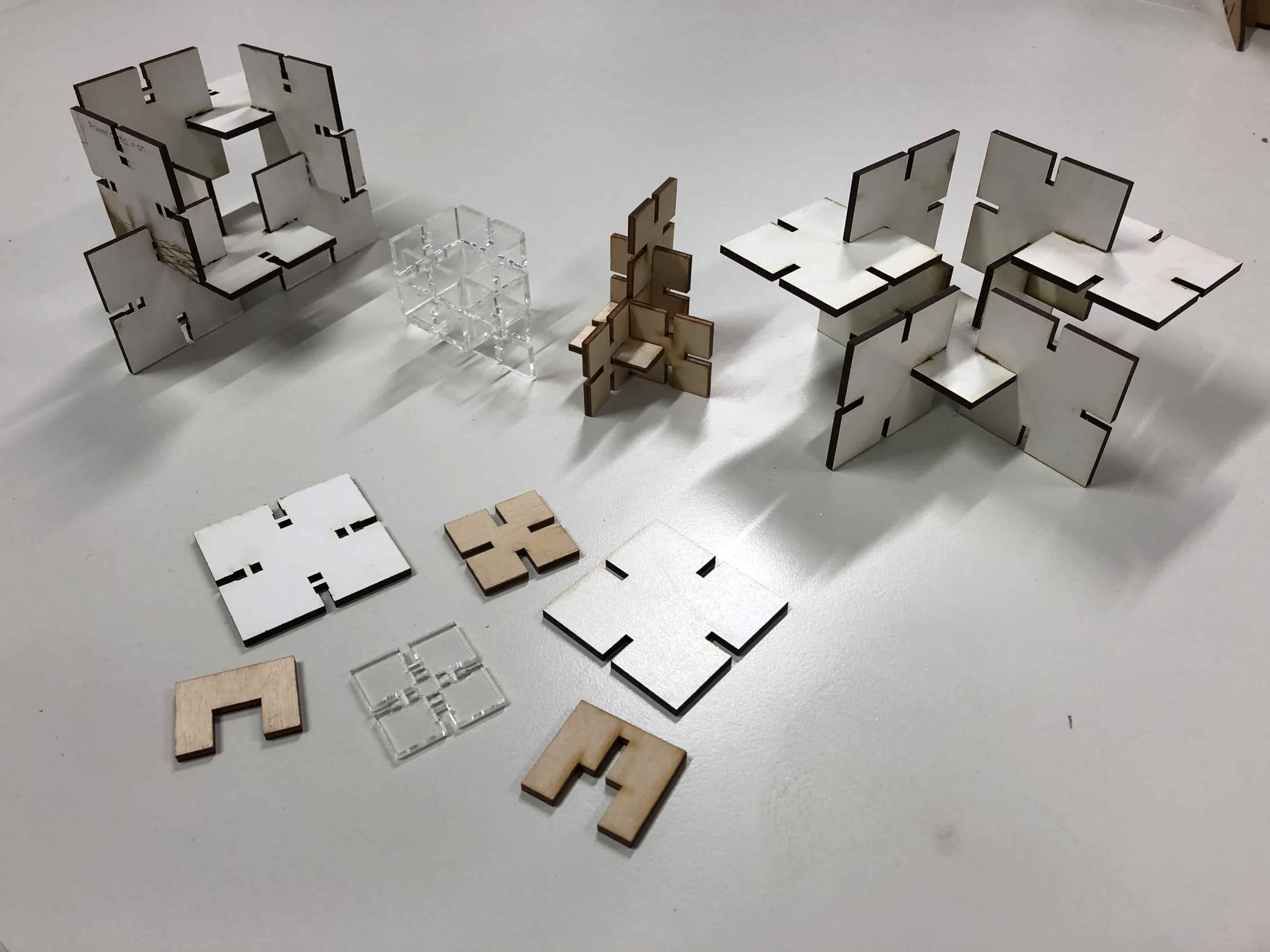
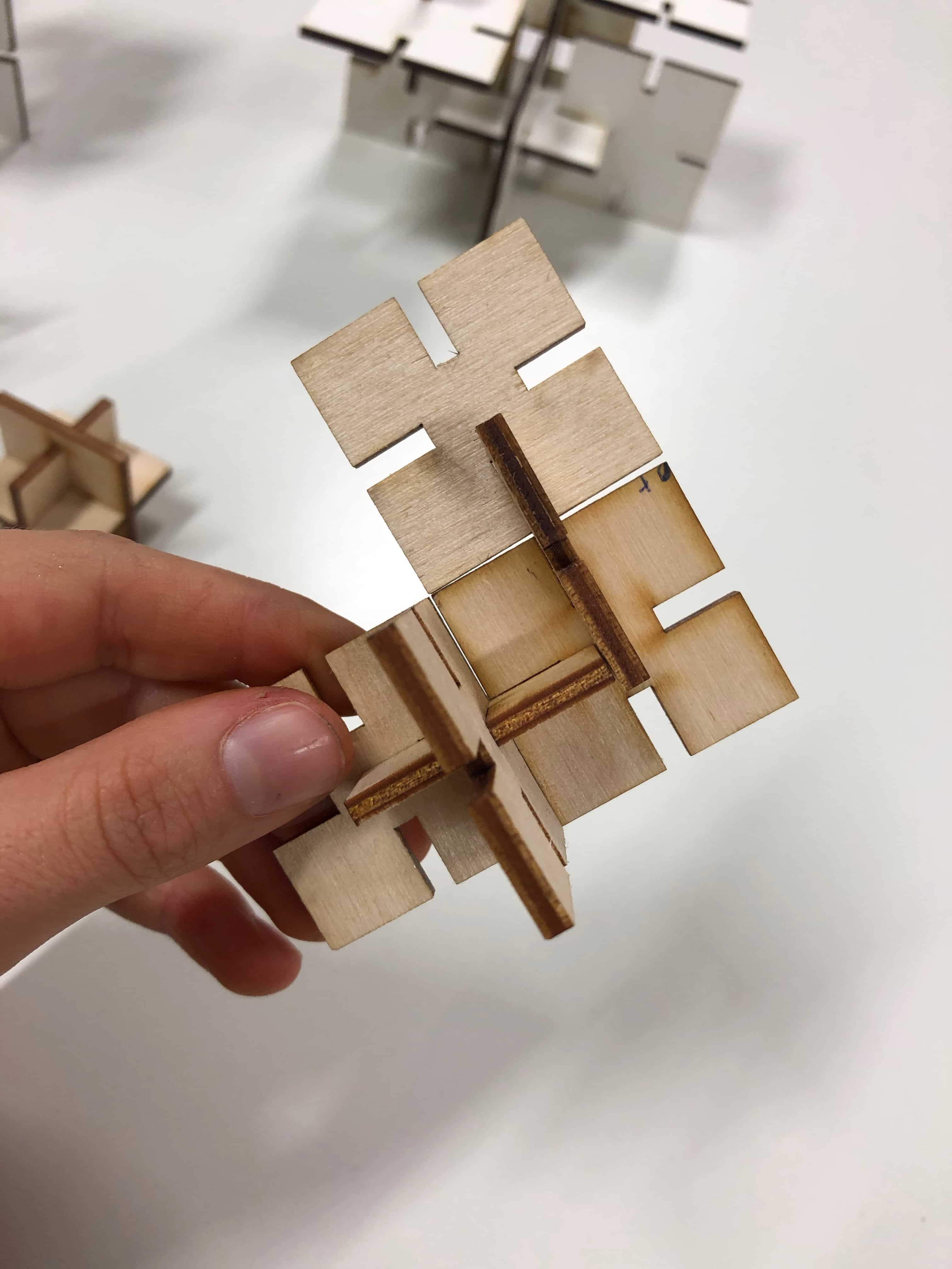
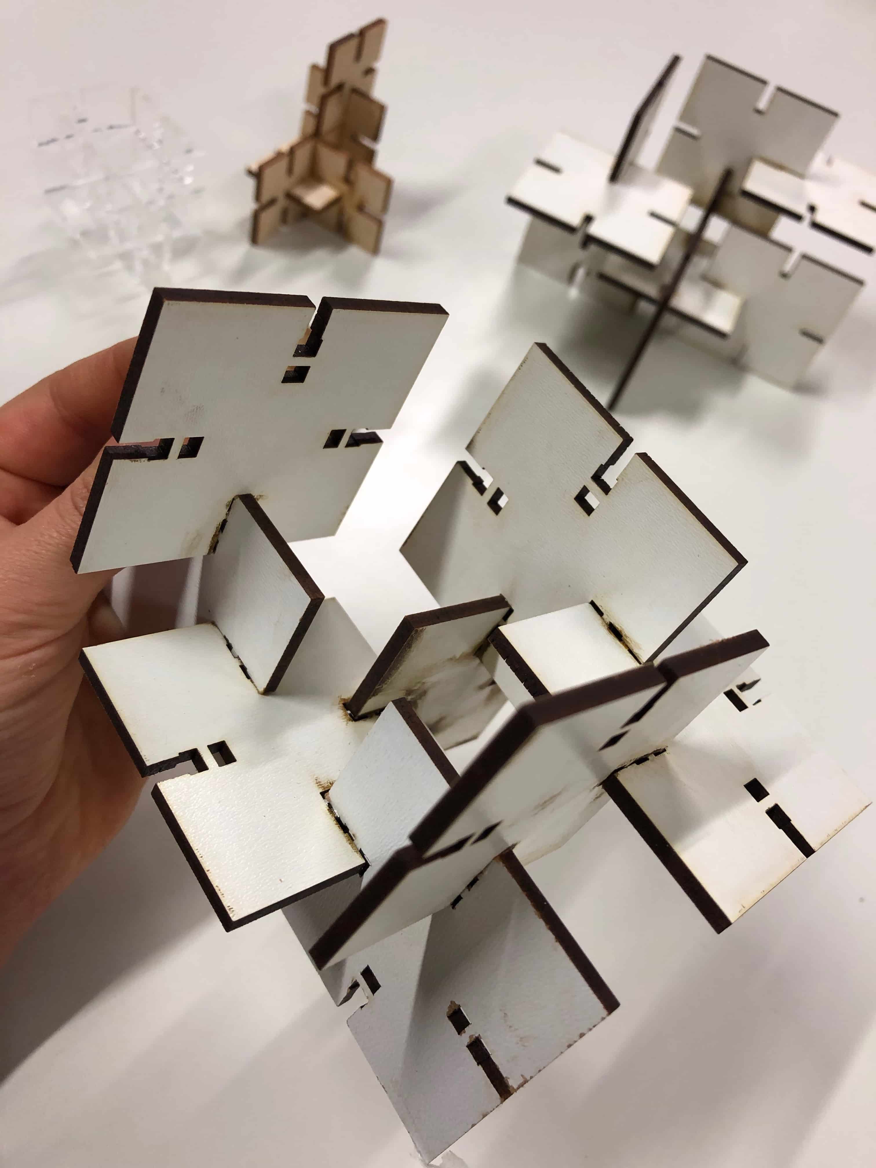
The goal was to expirement with different kind of materials and to find out if this would have an impact on the joints. Underneath you can see all the different parametric designs that I created.
The press-fit below was the first one I designed. I used 3mm plywood to find out if the joint is stable enough. Before starting the job I had to consider the kerf. The kerf is defined by the amount of the material that is removed in a cutting process. This depends on the material type and other conditional factors. Since the kerf for 3mm plywood is 0.1mm, the slots of my parametric design had to be 2.9mm large. Otherwise the joint would be way to large to fit properly.
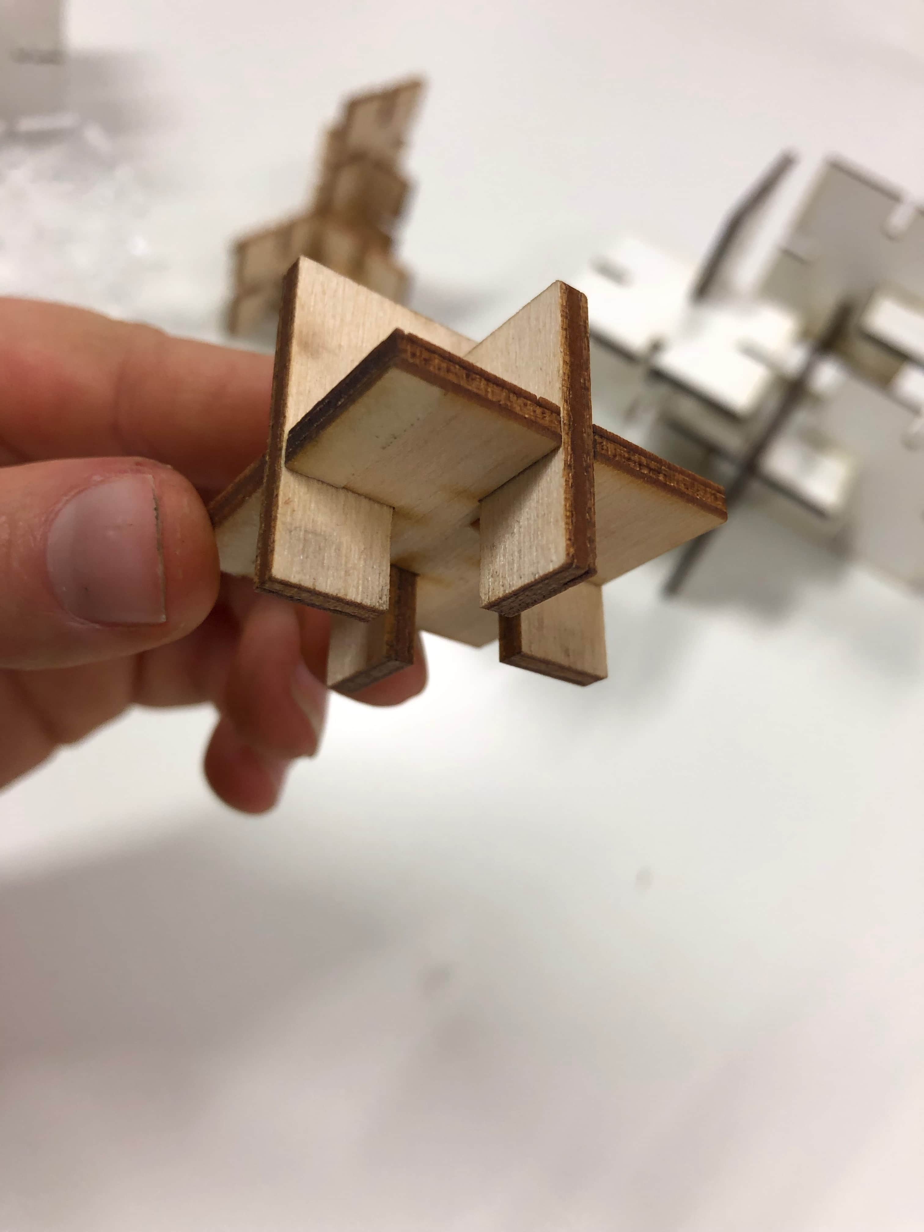
Next I tried the same joint with 3mm MDF and changed the lengt of the the slots by making them shorter. Still it fits perfectly as the other one.
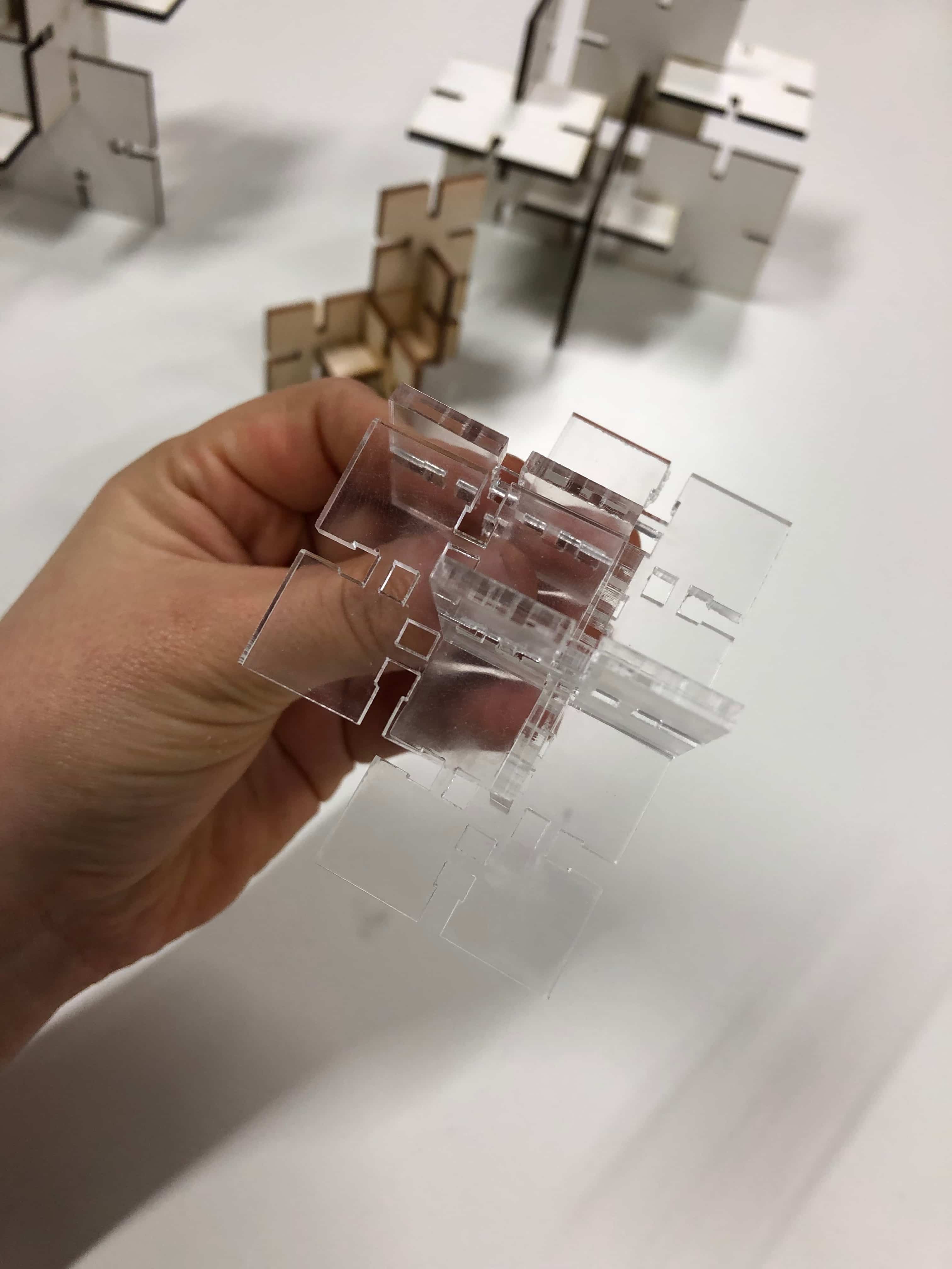
Then I made the joint with the snapping function. Here I detected that the slots were less stable wirh Acrilyc in comparison to MDF.
Using the Vinyl Cutter
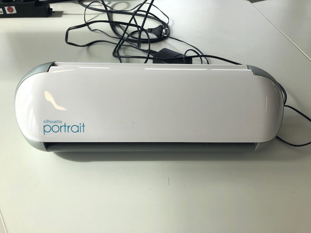
For this part of the assignment I used the Silhouette Portrait Plotter with the Silhouette Studio Software. The vincl cutter can be used for trimming vinyl or copper and other materials into many shapes or letters. The machine's blade can move between the x and y axis to cut a symbol. The vinyl cutter is the best machine to use if you want to create a particular symbol or shape which you can paste anywhere you want. To design the shape you can use programs like Adobe Illustrator.
Vinyl Design
As I am a total Marvel and Game of Thrones fan, I wanted to make a Marvel shirt and a GOT bag. To achieve this, I had to vectorize the PNG-files. To do this I used Adobe Illustrator. This is a very simple and easy procedure. First you have to import the image into Adobe Illustrator.
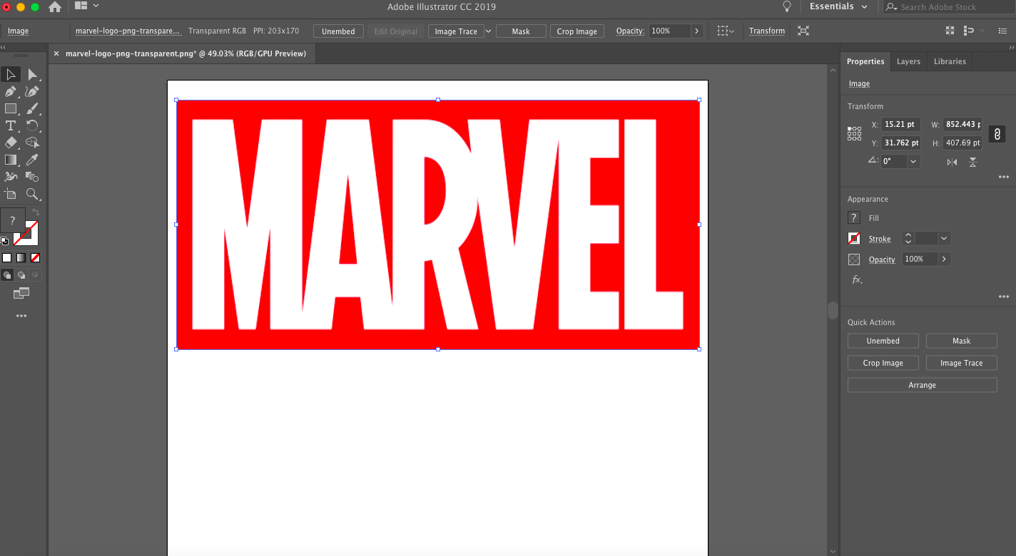
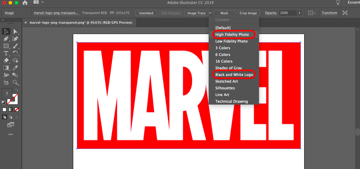
Then go to the control panel and select the arrow next to Image Trace. Here you can select either black and white logo or high fidelity photo. When you just want to vectorize a logo or a text choose the black and white logo.
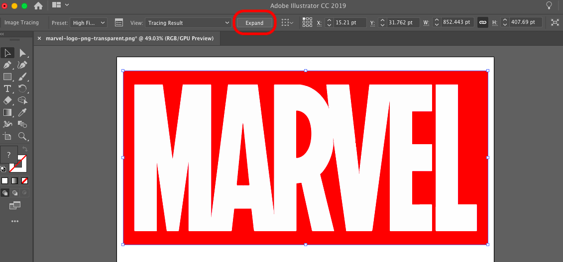
After the tracing process is complete press the Expand button, to convert the traces into paths. Now just select the object and check if everything worked out.
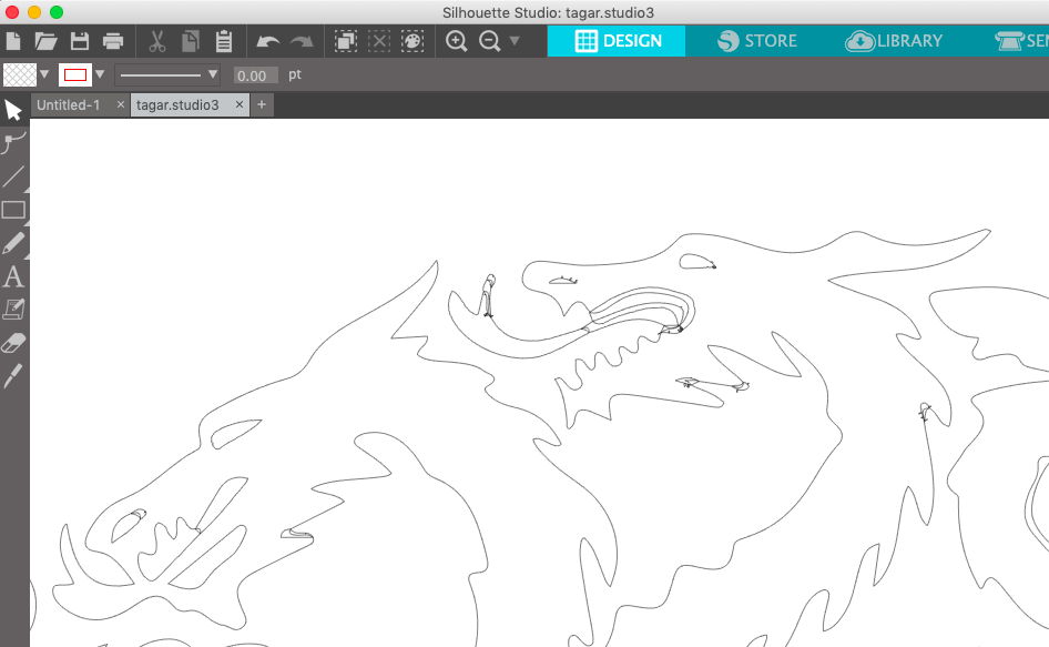
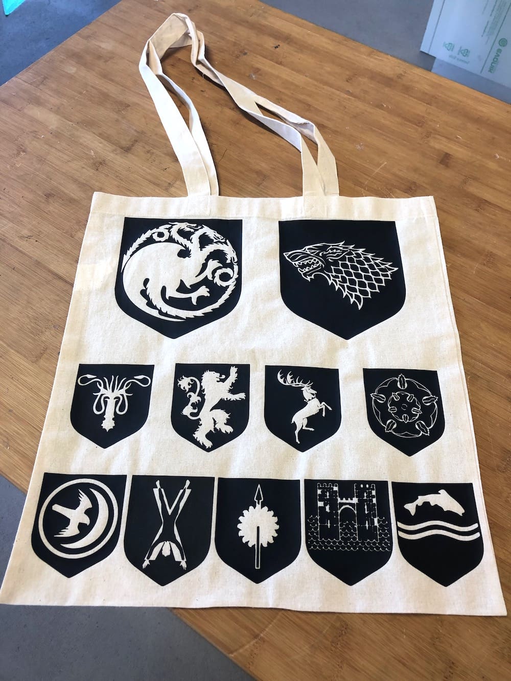
Here I faced some problems while vectorizing the several houses of Game of Thrones. As soon as I imported the path into the Silhouette Software, it created lines in strange places that looked like hair nodes. Moreover the path wasn't smooth enough to get a nice and clean cut with the vinyl cutter. So I went back to Illustrator and used a different kind of tracing process.
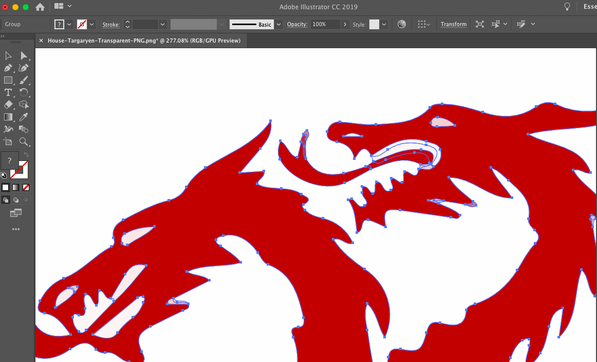
Instead of using the high fidelity photo process I used the black and white logo. After converting the traces you could already see a big difference between both methods.
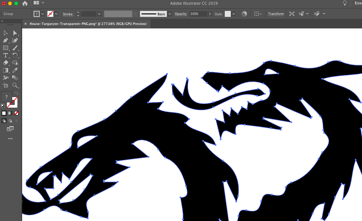
The problem was that the software got confused by the different color shapes in the image while using the high fidelity photo process. This is why I recommend you to only use this process with photos. In the black and white logo image process the software only needs to focus on two different colors and can identify the outline much easier.
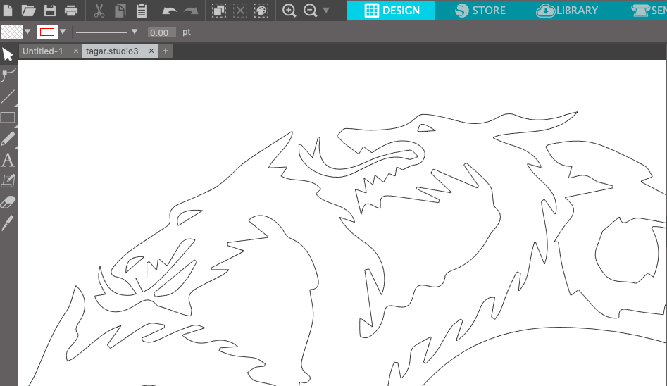
If I now import the new DXF-File into Silhouette everything is even. Now we are able to achieve a nice and clean cut.
Cutting the Vinyl
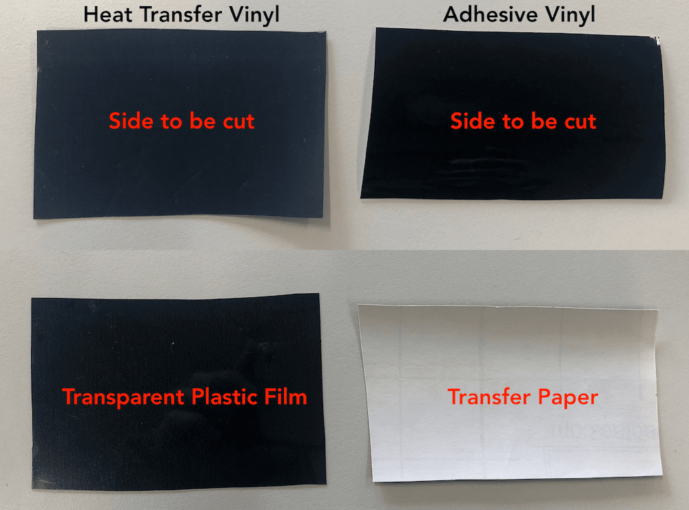
There are two basic types of vinyl: Adhesive Vinyl and Heat Transfer Vinyl. Adhesive Vinyl is a thin flexible material with an adhesive on the backside, which allows you to paste it on all kinds of smooth, hard surfaces. Heat Transfer Vinyl (T-shirt Vinyl) is a similar material only that this kind of vinyl can be paste on fabric surfaces (or any surface that can stand the heat). Because they both look pretty much the same, you can only tell the difference by checking the adhesive. Adhesive Vinyl always has transfer paper underneath and when you peel it of it is very sticky. Heat Transfer Vinyl, on the other hand, does not have a transfer paper. Instead it has a transparent plastic film that covers the top of the vinyl. The other side is where the adhesive is and it's not sticky. You always cut on the adhesive side (usually it's the one that's not shiny).
To send a job to the Portrait Plotter, you have to download the Silhouette Studio Software. Then connect the printer to your computer.
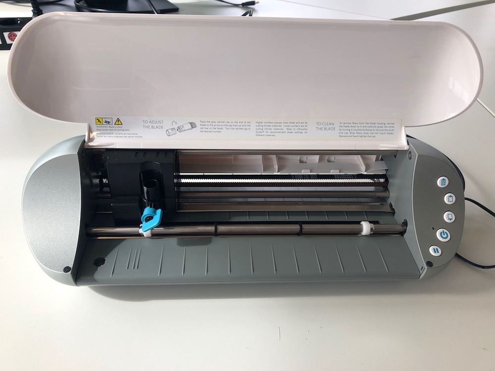
When you open the flap of the vinyl cutter, you will see that it basically looks like a normal printer. Only that it uses a blade instead of ink.
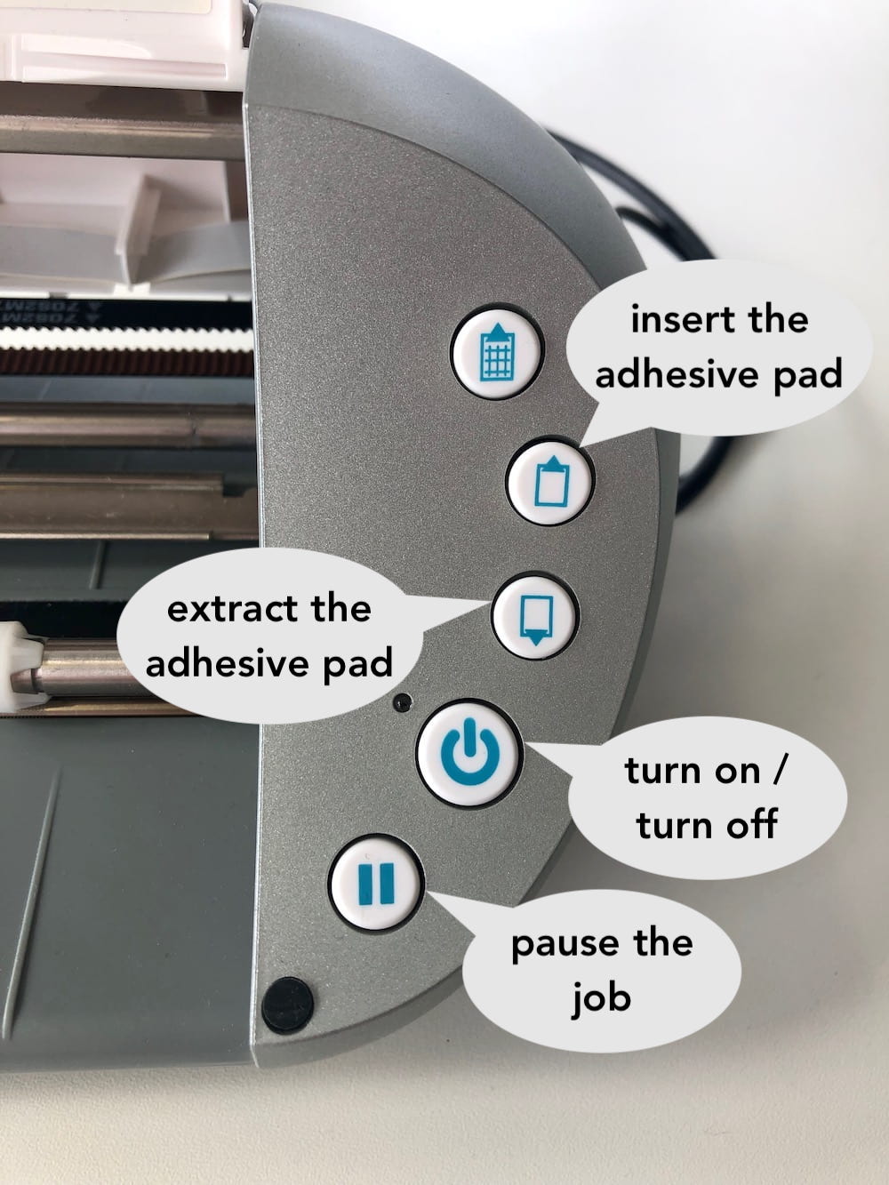
On the right side of the Portrait you have the control panel. In the picture underneath you find an explanation of all the buttons you need to use.
Before you start you need to set the height of the blade. I recommend you to always make a test cut with a piece of vinyl, to be sure of how deep the blade needs to be. The goal is to cut everything out by leaving the plastic film of the vinyl untouched. Remove the knife tool and use the knob to decrease or increase the quatity of the blade.
As you can see in the video the blade is very small and thin. Usually if it's sharp only the tip of the knife needs to stick out. To change the value just rotate the knob clockwise.
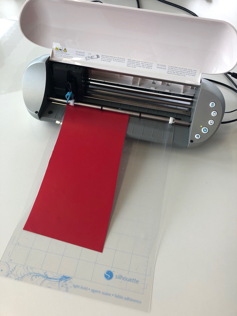
Now paste the piece of vinyl on top of the cutting mat and insert it. Always consider which vinyl you are using. Since I am using the heat transfer vinyl, the adhesive side of the vinyl is the one that I will cut. This means, that the side with the plastic film (the side that looks shiny) has to stick on the cutting mat of the printer.
Next make a test cut to be sure that the blade doesn't cut through the transparent film.
The blade was set to 2 and I managed to create a beautiful cut without damaging the film underneath.
After I've adjusted everything and made a test cut, I can start with the actual job. First of all I import the DXF-File into the Silhouette Software.
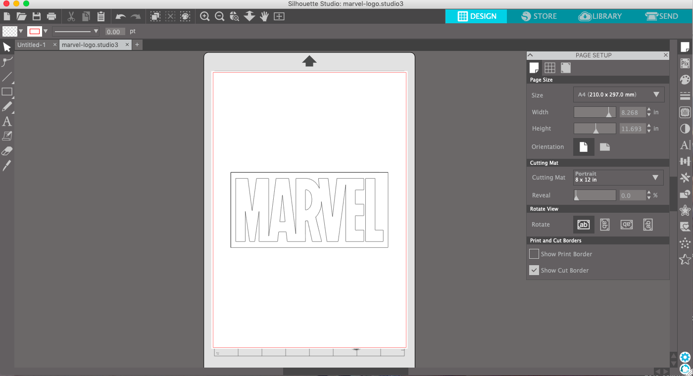
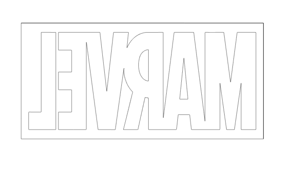
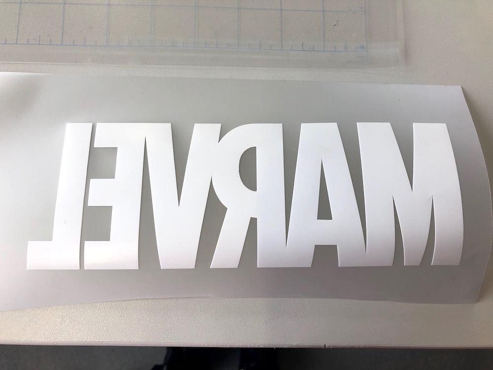
Because we are cutting on the backside (adhesive side) of the vinyl we need to mirror the word. To do this go to Object --> Mirror --> Flip Horizontally.
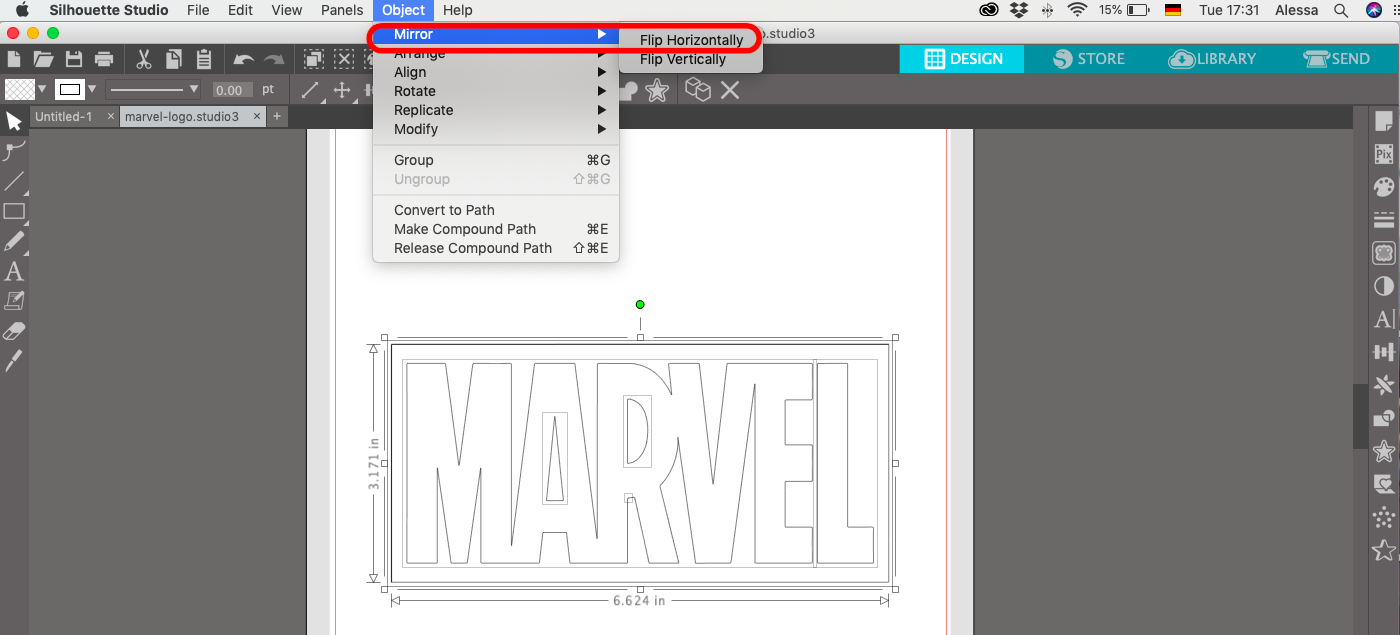
Below you can see how it needs to look like.
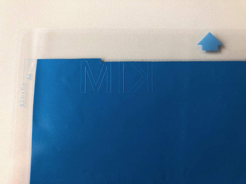
Thereafter you can place the image in the left upper corner. I also decided to enlarge the logo.
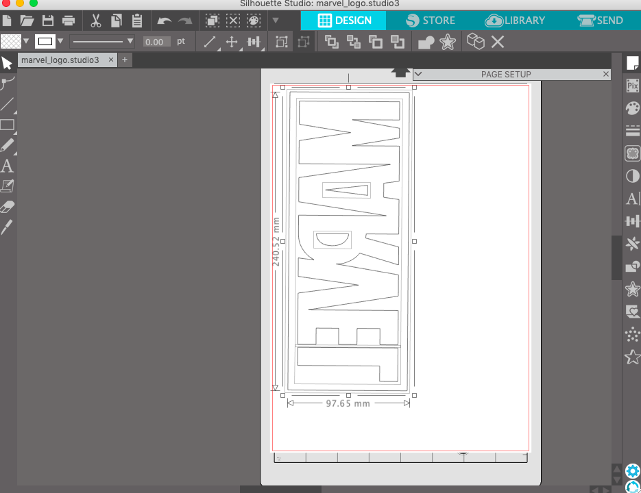
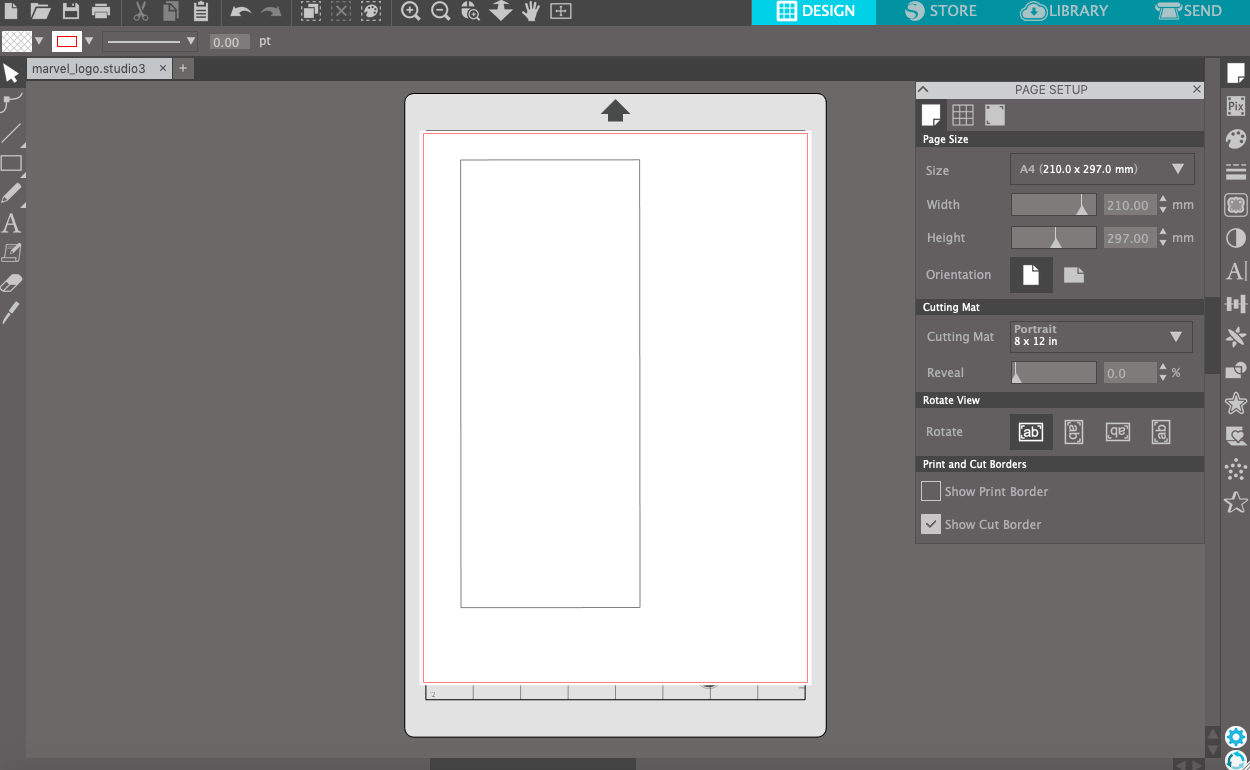
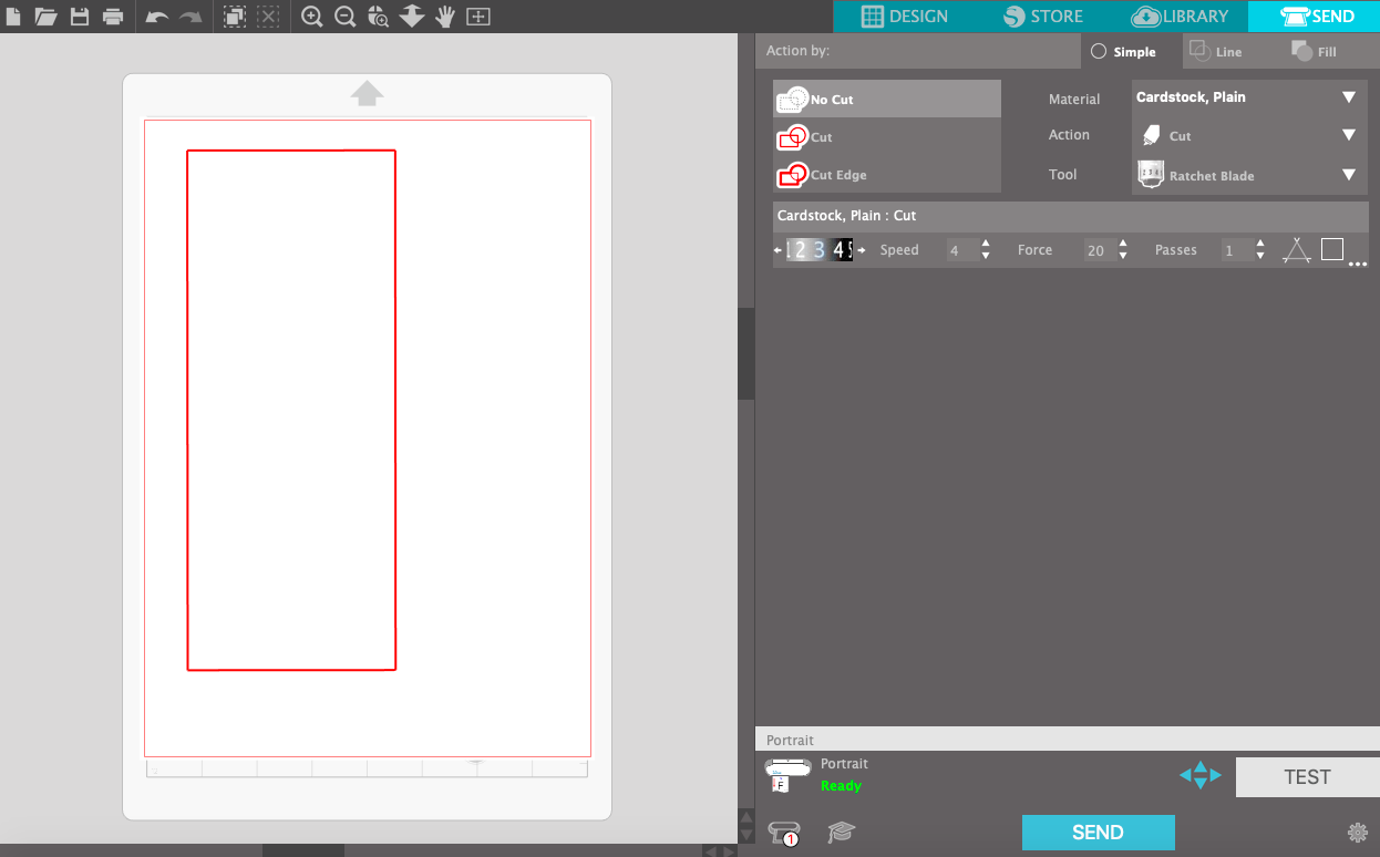
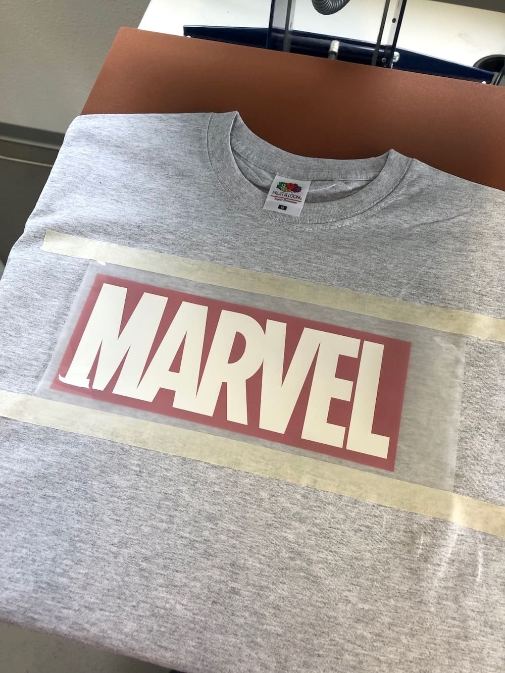
The Marvel logo has a red background with white letters. So I first start to cut the background and remove the letters. Before you send the job always be certain that you selected the proper vinyl cutter mat. In this case the portrait mat. I also like to set the Size of the mat, cause then you will have a realistic output of the position of your design.
Finally you can send the job and the machine will do the remaining.
After peeling of the excess material around the image, you can place it in the center of the shirt.
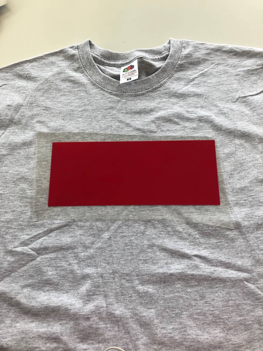
Now I only need to use the heat press to attach the vinyl properly.
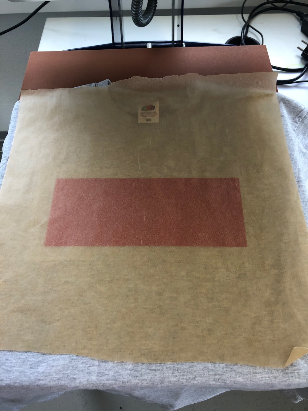
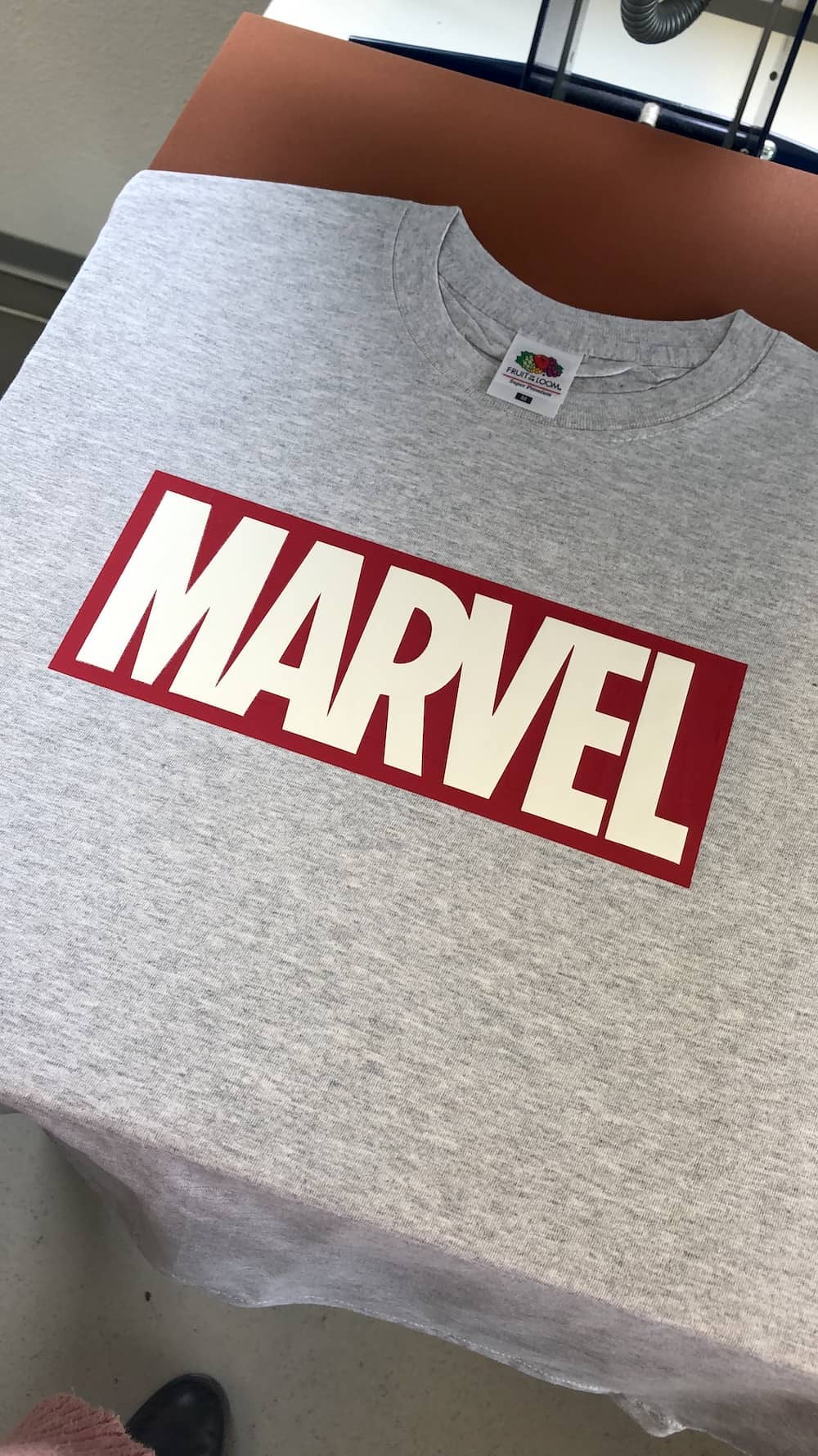
Next remove the transparent film carefully, because the vinyl is still heat. In the video you can see how good and nice the vinyl is attached to the shirt.
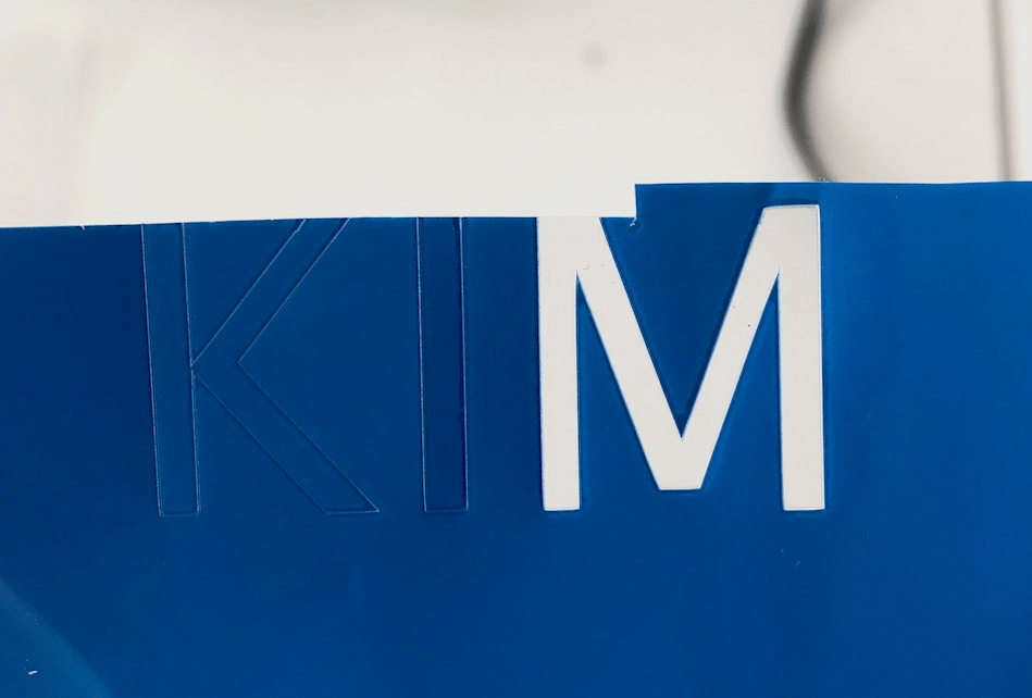
For the Marvel logo I also had to remove the excess material around and inside the image, to then place it on top of the background.
I simply overlapped the vinyl and the result is incredible.
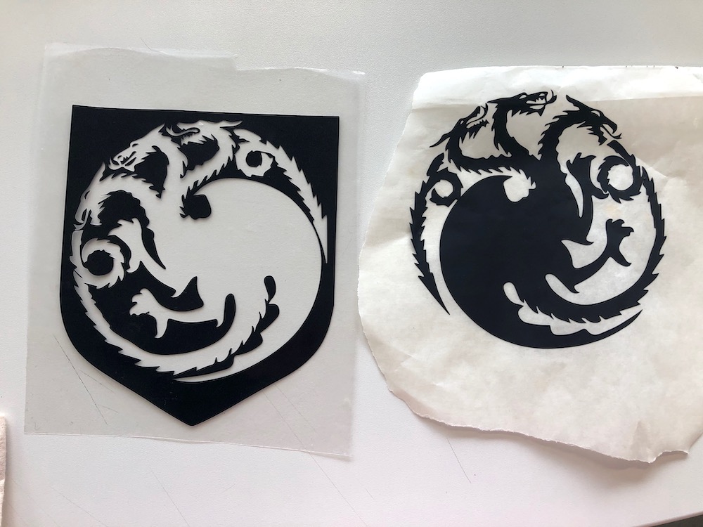
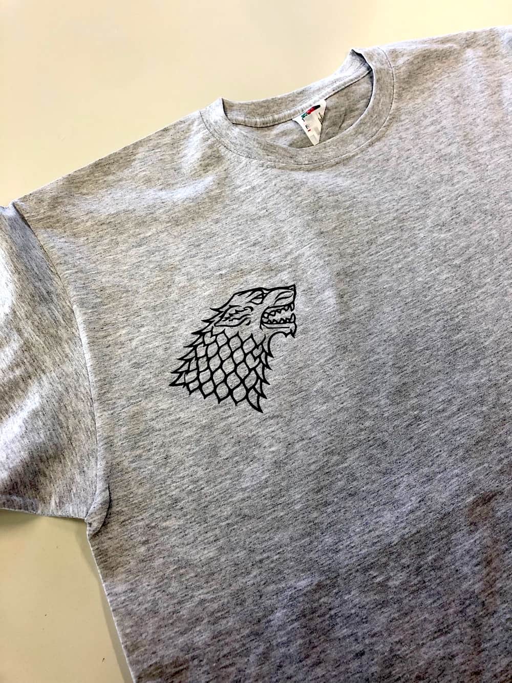
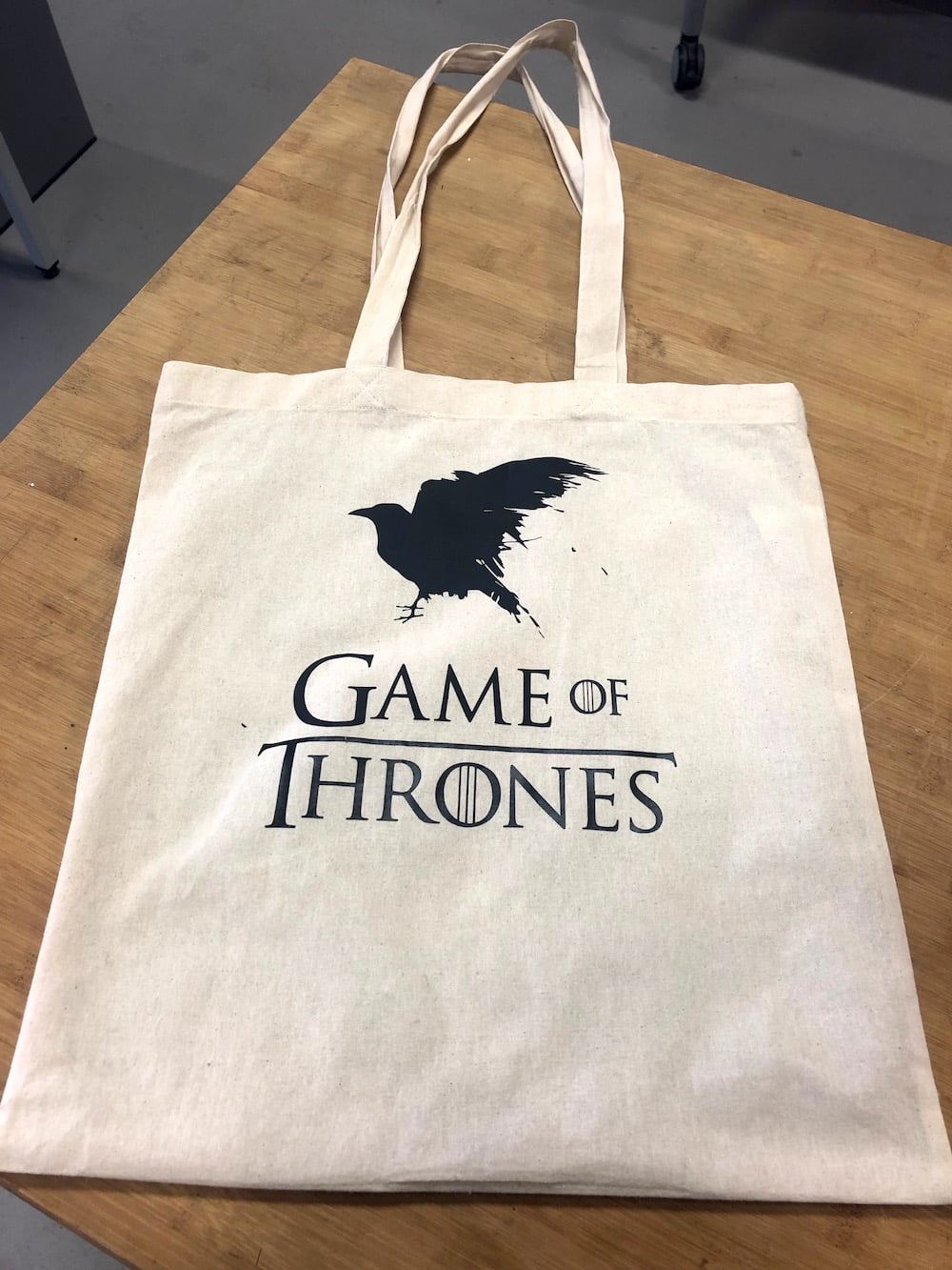
For the Game of Thrones bag I just repeated the steps. Below you have some pictures of the process. I thought it would be such a waste to peel of the dragon and the wolf and throw them away. So I tried my best to don't expend the vinyl while removing it. And so I managed to remove the inside of both houses carfully without destroying them and paste them on a piece of transferring paper. Now I can use both designs.
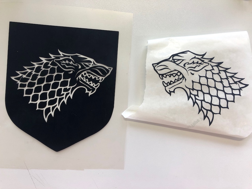
Thereby I could use the inside of the wolf to paste it on a shirt.
Underneath you have the finished bag which really rocks.
Download Files
DXF-Files
Marvel LogoGame of Thrones Logo
Three-eyed Raven - GOT
Game of Thrones - The Great Houses
Parametric Design