Computer-Controlled Machining
For this week's individual assignment we had to make something big usig the CNC machine. The goal was to design, mill and then assemble the pieces.
CNC Machine
CNC (Computer Numerical Control) machining is a subtractive manufacturing technology. Objects are created by removing material from a solid block using a variety of cutting tools. Almost every material can be CNC machined such as metals, plastics, foam, and wood. The basic CNC process can be broken down into 3 steps. The engineer first designs the CAD model of the part. The machinist then turns the CAD file into a CNC program (G-code) and sets up the machine. Finally, the CNC system executes all machining operations with little supervision, removing material and creating the objects. You can have a 3 axis or a 5 axis CNC machine.
Group Assignment
For this week's group assignment we had to test runout, alignment, speeds, feeds, and toolpaths of our CNC machine. You can find the documentaion here.
Sketching
To create my design I used Autodesk Fusion 360. At first I hat to come up with a cool idea for this assignment, so I searched the internet for inspiration. After a while I decided to design a foosball table. To get a rough idea of how all the parts are composed, I started drawing a sketch. Since the size of the wood panel was 250x120cm, I had to modify the original size of the foosball table. The original length of the soccer field is 120x68cm. I scaled everything except of the table legs with a factor of 0.66667 so that my soccer field is 80x45. I did this, because if I would have used the original sizes, I wouldn't have enough space to mill the table leg's. I did a couple of calculations, since I had to design 9 pieces (excluding the leg's).
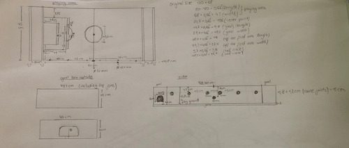
In addition, the goal was to realize a press construction, so that I also had to include joints in my design. Moreover I chose to use multiplex because it is a very strong material. The material thickness will be 12mm. I measured it beforehand to make sure I didn't have any tolerance and it was as the manufacturer said 12mm.
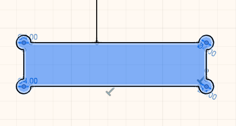
Since the machine is not able to produce sharp edges for an internal cut, you need to add circles at the corners of your joints. I have created 4.2 mm circles so that the tool has enough space to pass through. The size of the tool I use is 4 mm. Therefore, the circles at the corner must be slightly larger so that the tool can simply cut it out, otherwise it would drill the corners. This also ensures that the objects fit into each other after assembly. I also decided to don't have a tolerance for the joints so that everything is very tight.
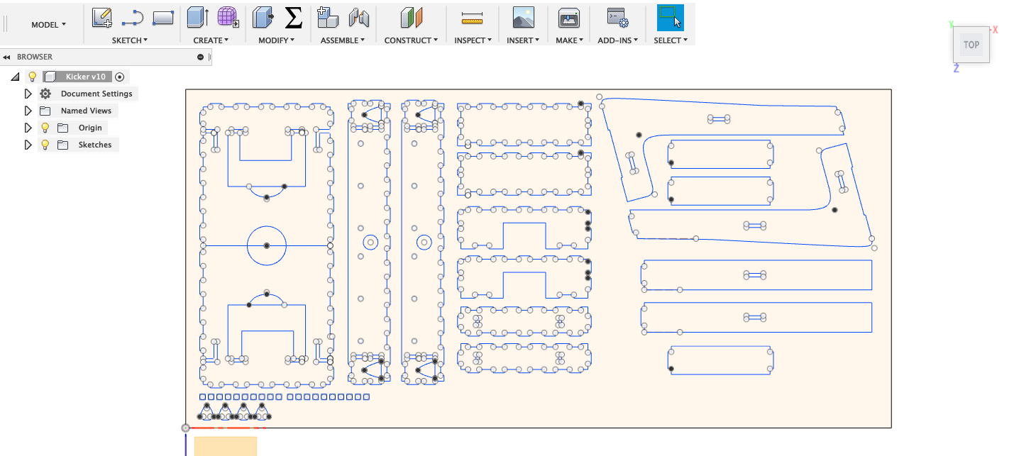
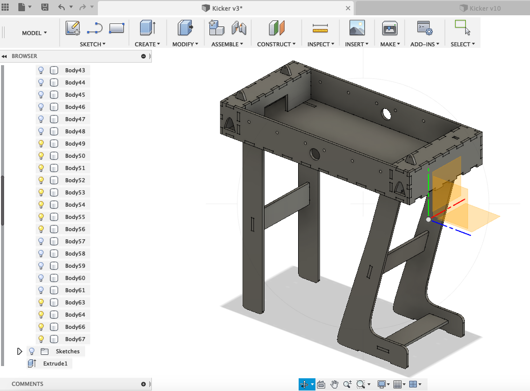
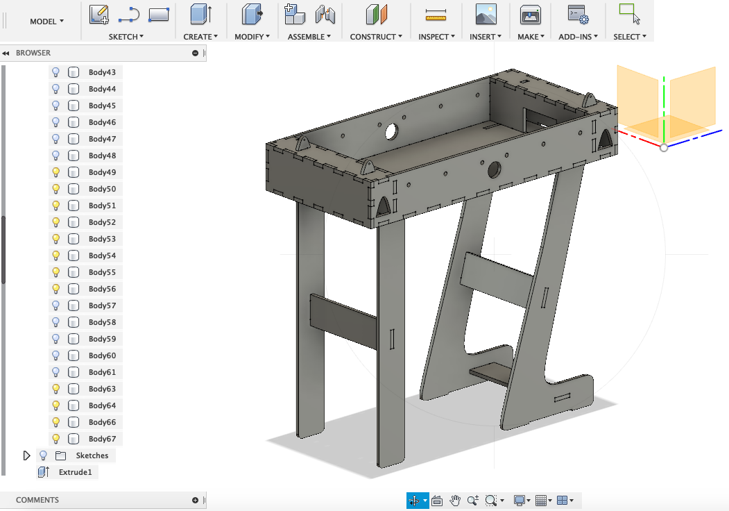
After you have finished with sketching the model, you must always extrude the parts and asemble them in the software you are using. This is very critical as it shows you whether you have placed everything in the right place.
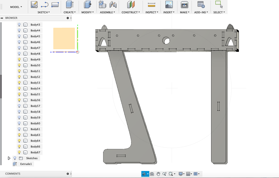
As a result we obtain a nice looking foosball table.
Rhinoceros
Usually when you design something for the CNC Machine, you will need to start several jobs. In order to keep the jobs apart, you have to assign them to individual layers. Here there are three important categories that need to be considered. The jobs/layers can be assigned by:
Since in Fusion 360 you are not able to allocate the design to different layers, you have to import the DXF file into Rhino.
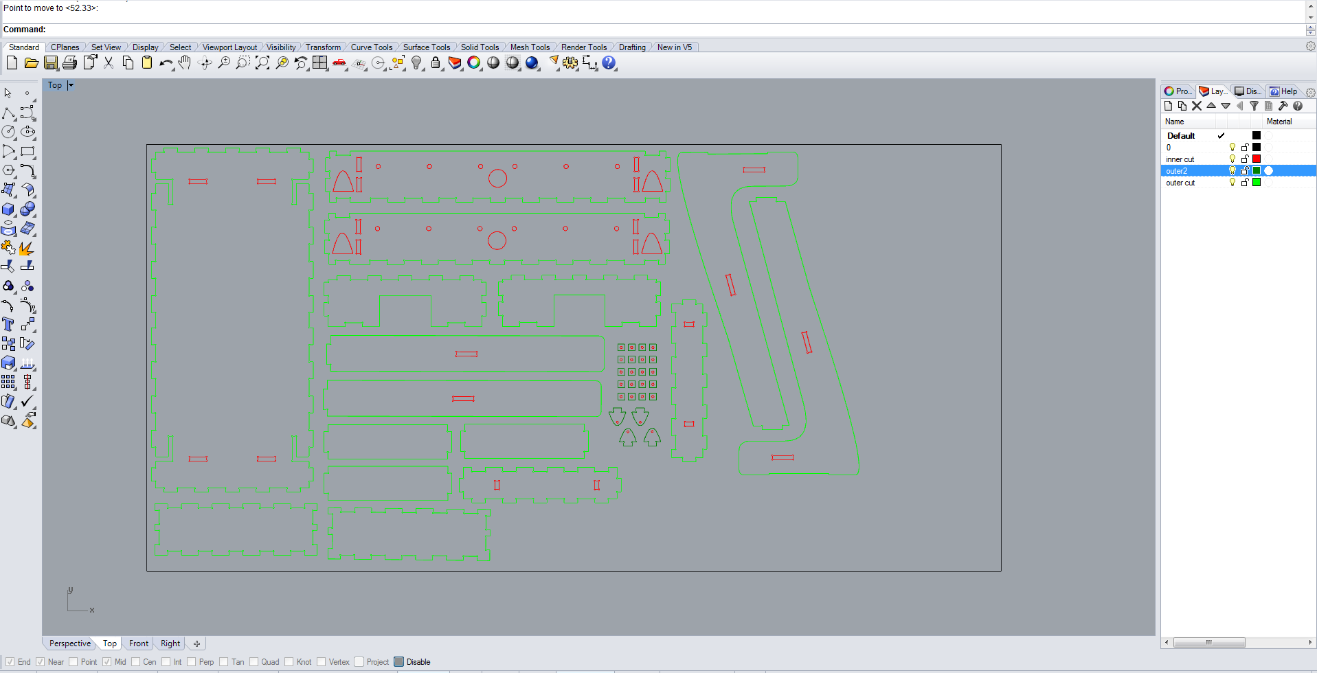
In case of my job, the tool size for all the jobs is 4mm, so I only distinguished between inside and outside cuts. Moreover I had two outer cuts, one for the large parts and one the small parts. Because with the smaller parts I had to make sure that these parts didn't fly out. The rule of thumb is to go from the inside to the outside in order to achieve the best result. The file with the different layers is then saved and imported into the software of the machine.
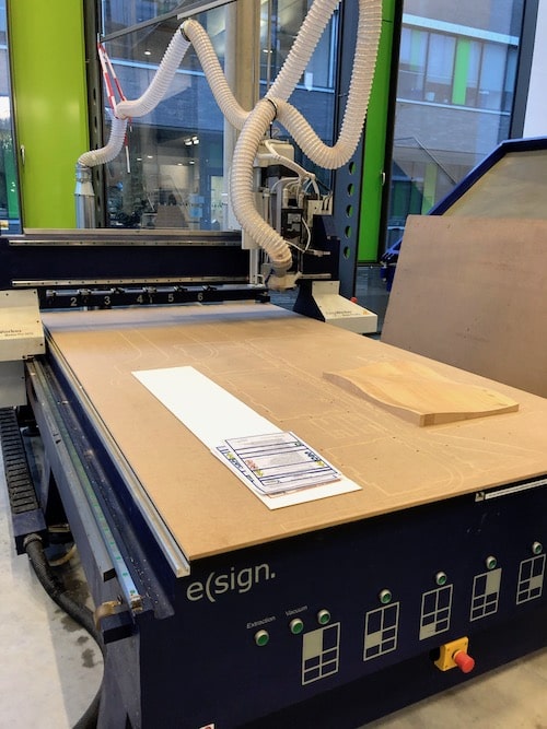
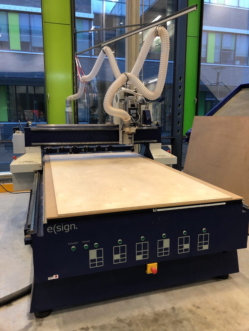
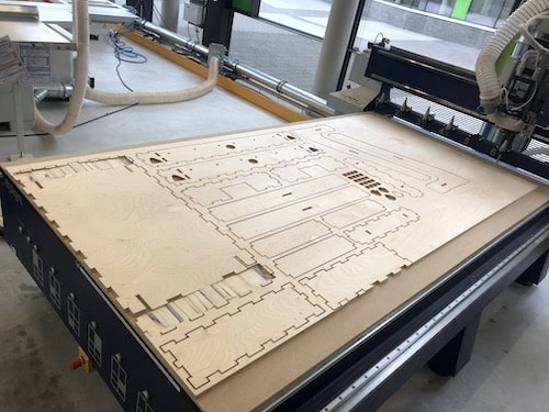
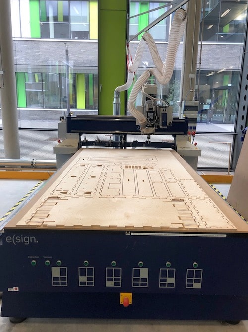
Using the CNC Machine
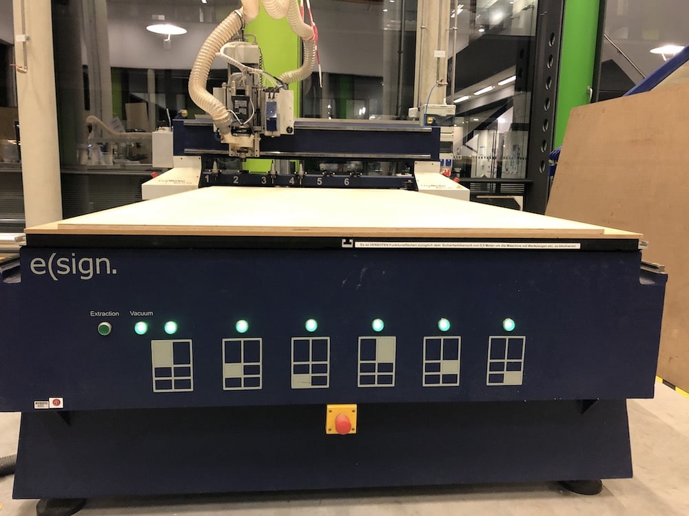
The machine we use is the EasyWorker MasterPro 2513. This machine comes with special software which can load DXF files and convert them into GCODE files. Several important steps are required to troubleshoot the machine.
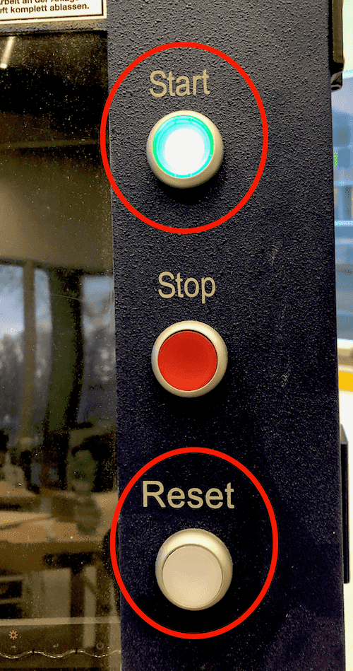
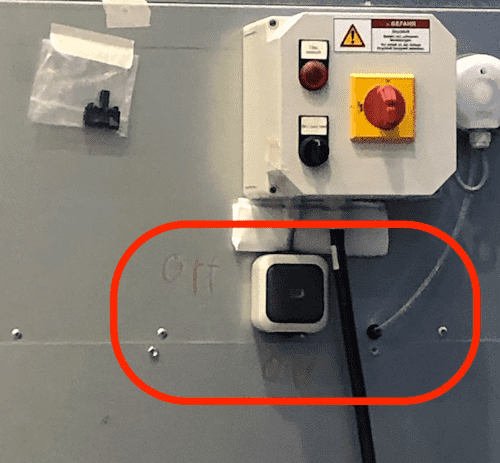
First you have to turn the main switch to turn on the machine.

Then you have to reset the machine and start it.
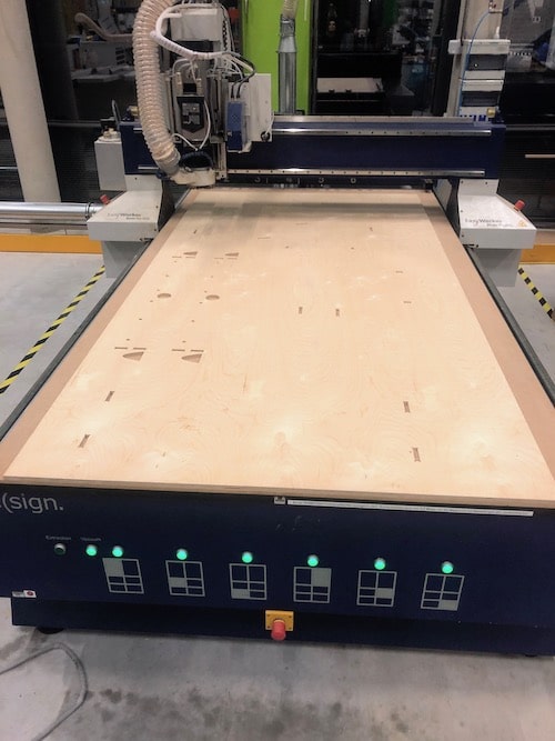
Next, make sure the bed of the machine is clear before proceeding and then start the software CNC4.01.
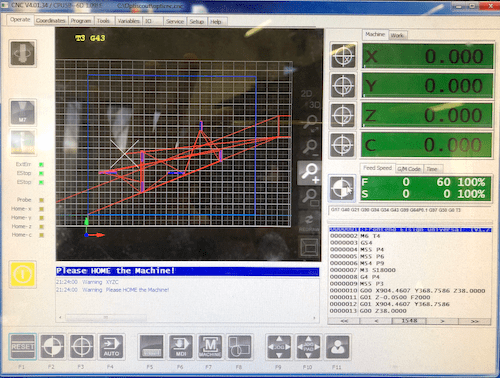
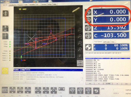
After starting the software, you will have to home the machine. Below you can see the interface of the software, which shows a vector model in the middle, which displays the job directly as soon as you load it into the software. On the right side one can see the coordinates of the X, Y and Z axes, the GCODE executed by the machine and the time required to execute the job. At the moment we are in the operation tab. Here the user can operate the machine and change things such as the tool, the feed rate and starting or stoping the job.
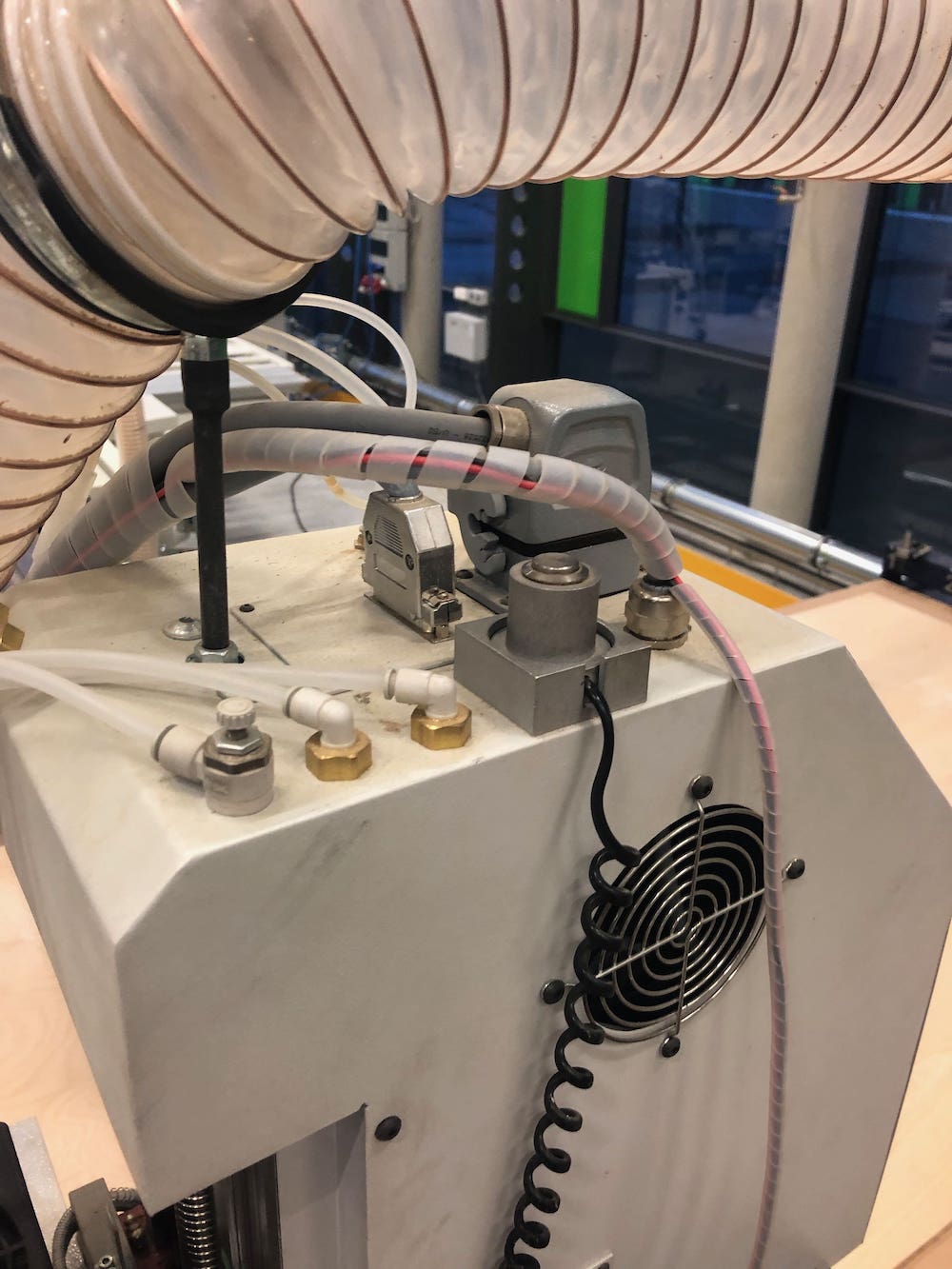
To home the machine I used the remote control. There is a side button on the right of the control, which needs to be pressed simultaneously with the buttons from the remote. This is where the basic controls are located, as found in the software.
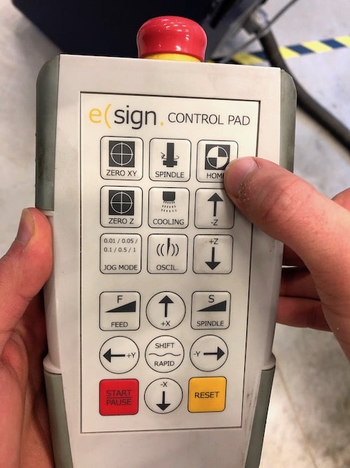
Next you will have to set the zero point, which is the starting point of your job. To do this I used the remote control. By pressing the shift button and one of the axes you can move at high speed. In our case, the origin point is always the lower left corner. To check if you have set the X and Y coordinates, go to the software and make sure it displays zero.
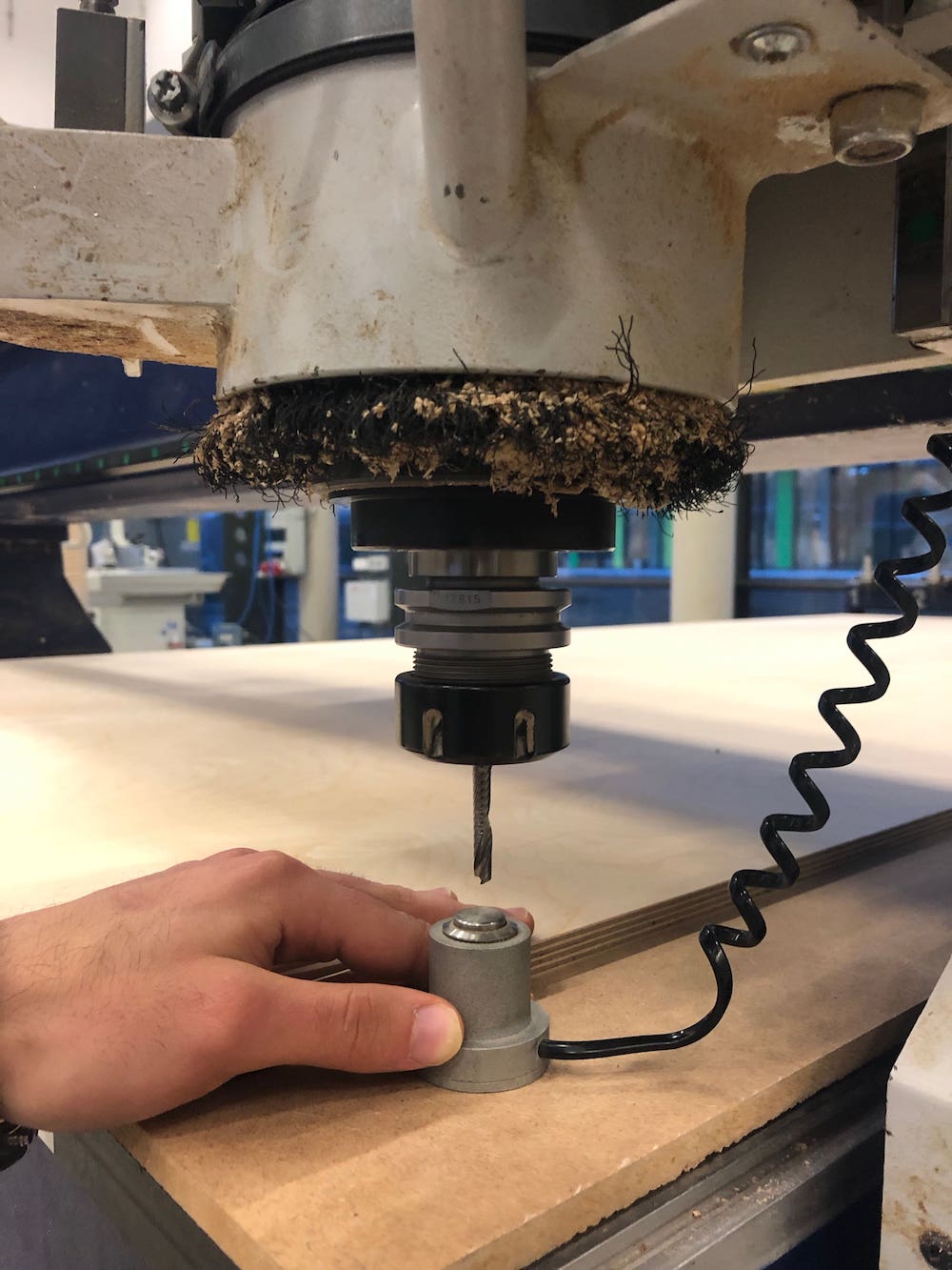
To adjust the Z-axis, you must use the sensor that measures the exact height of the bed. You can find the sensor on the head of the machine. To set the Z point we need a second person that holds the sensor. Always check if the person is ready, since the machine is going to move.
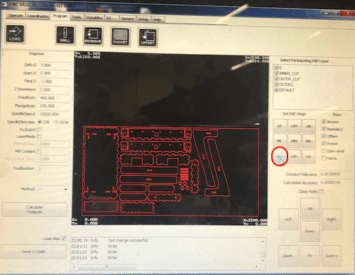
Once you have set the origin point, you can switch to the Program tab, where we generate the GCODE. First of all we make sure that we select the lower left as orgin point of the DXF. Then we first choose the starting layer and then we can configure the settings with which we execute the job. Morover make sure you select the correct mask. For an inside or outside cut, select the offset mask. In order to achieve the best result, we start with the inside job.
The settings used to cut the foosball table for the 12 mm plywood are:
Finally we generate the GCODE and save it.
Before launching the job there are some crytical aspects to consider. These are:
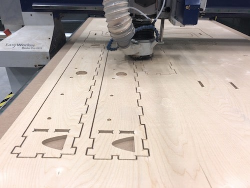
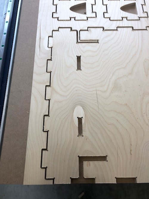
Inside Cut
Outside Cut
3D Design
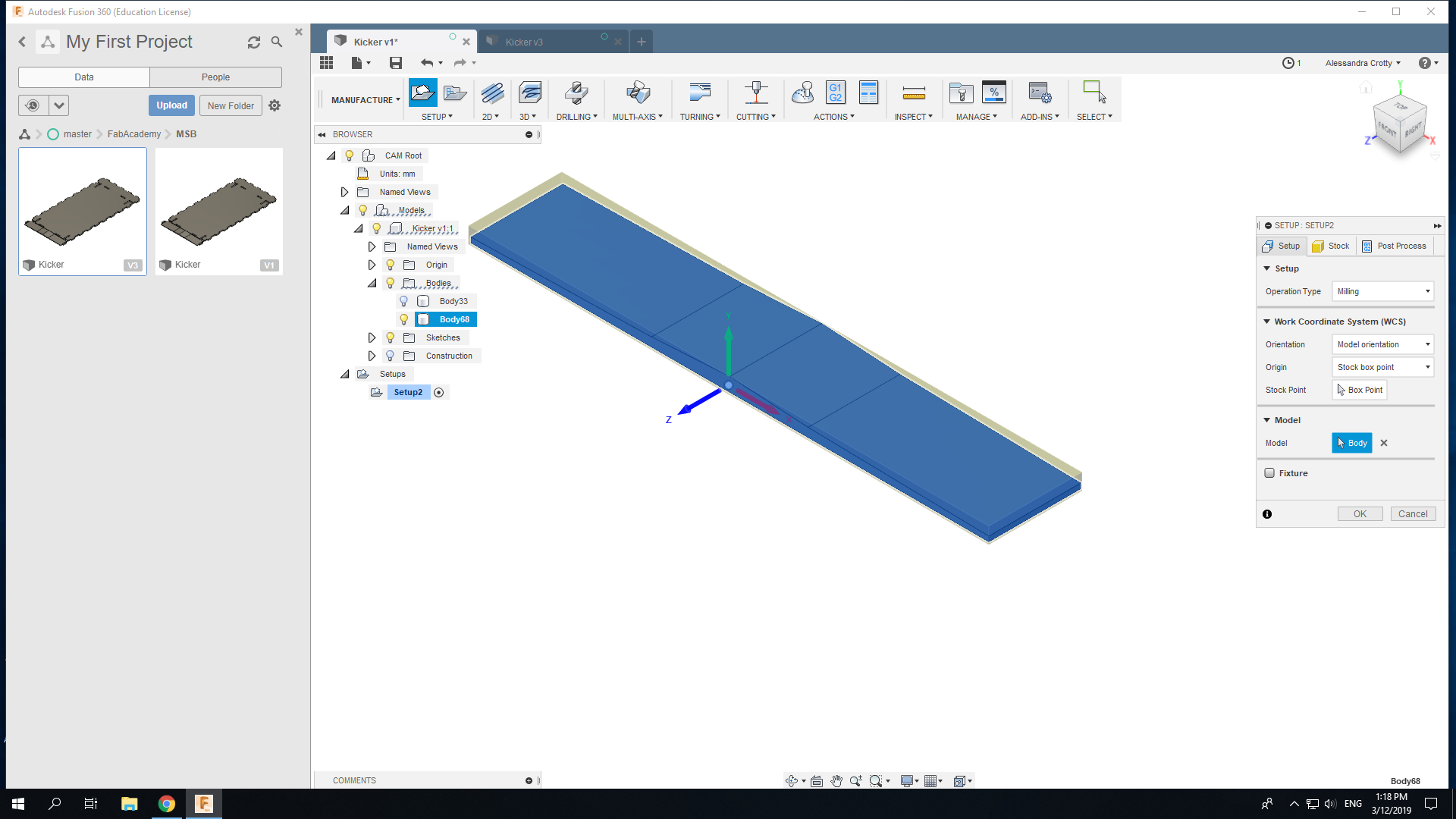
To make the ball roll as soon as someone scored, I had to mill a slide. To mill in 3D you have to change into the CAM processor mode, which generates the GCode for you.
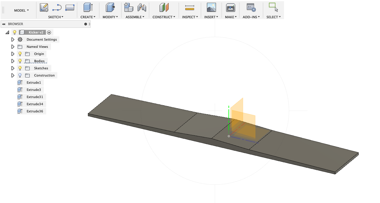
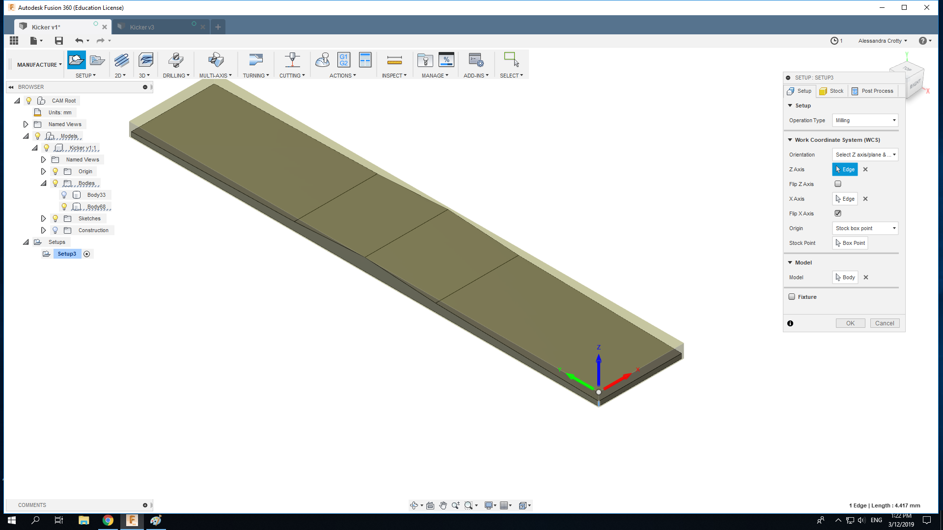
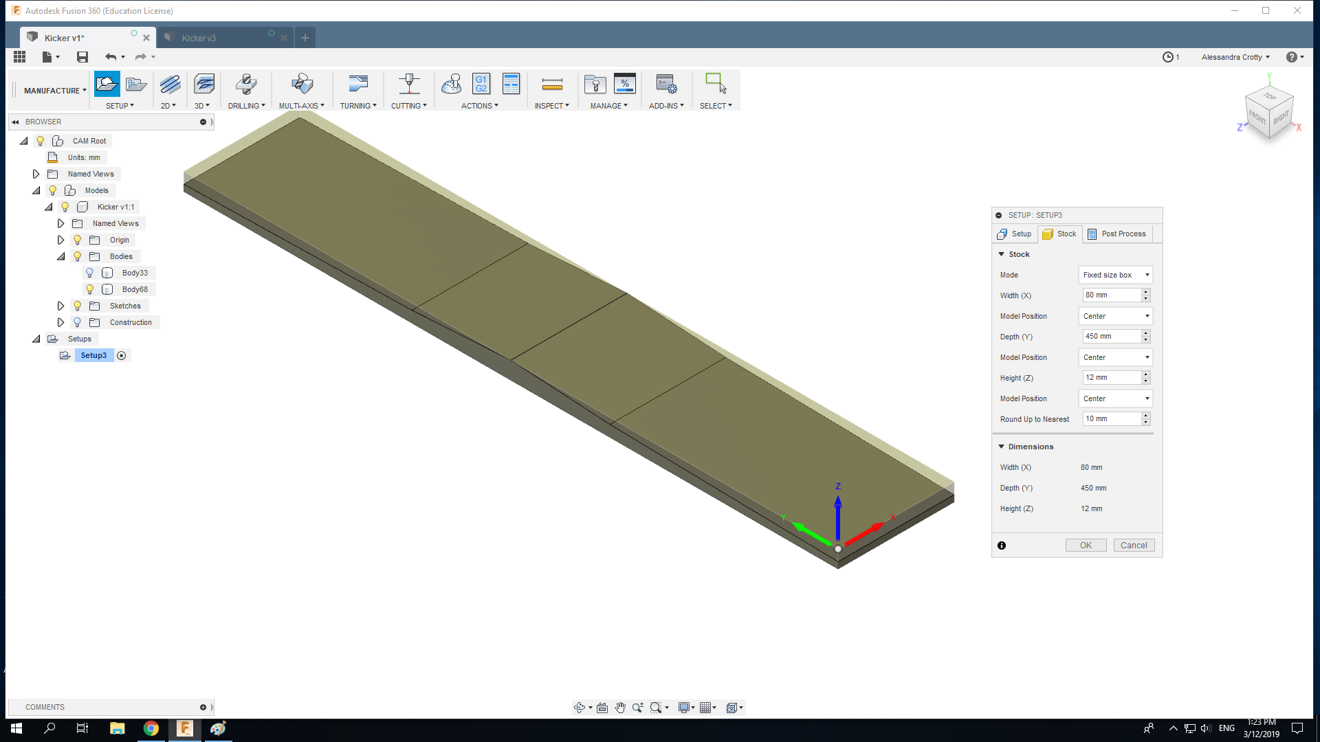
Here a new setup needs to be created. Important is to indicate the correct axes that match the block positioned inside the CNC machine as well as the origin point of the tool. In this case, it is the top-left corner.
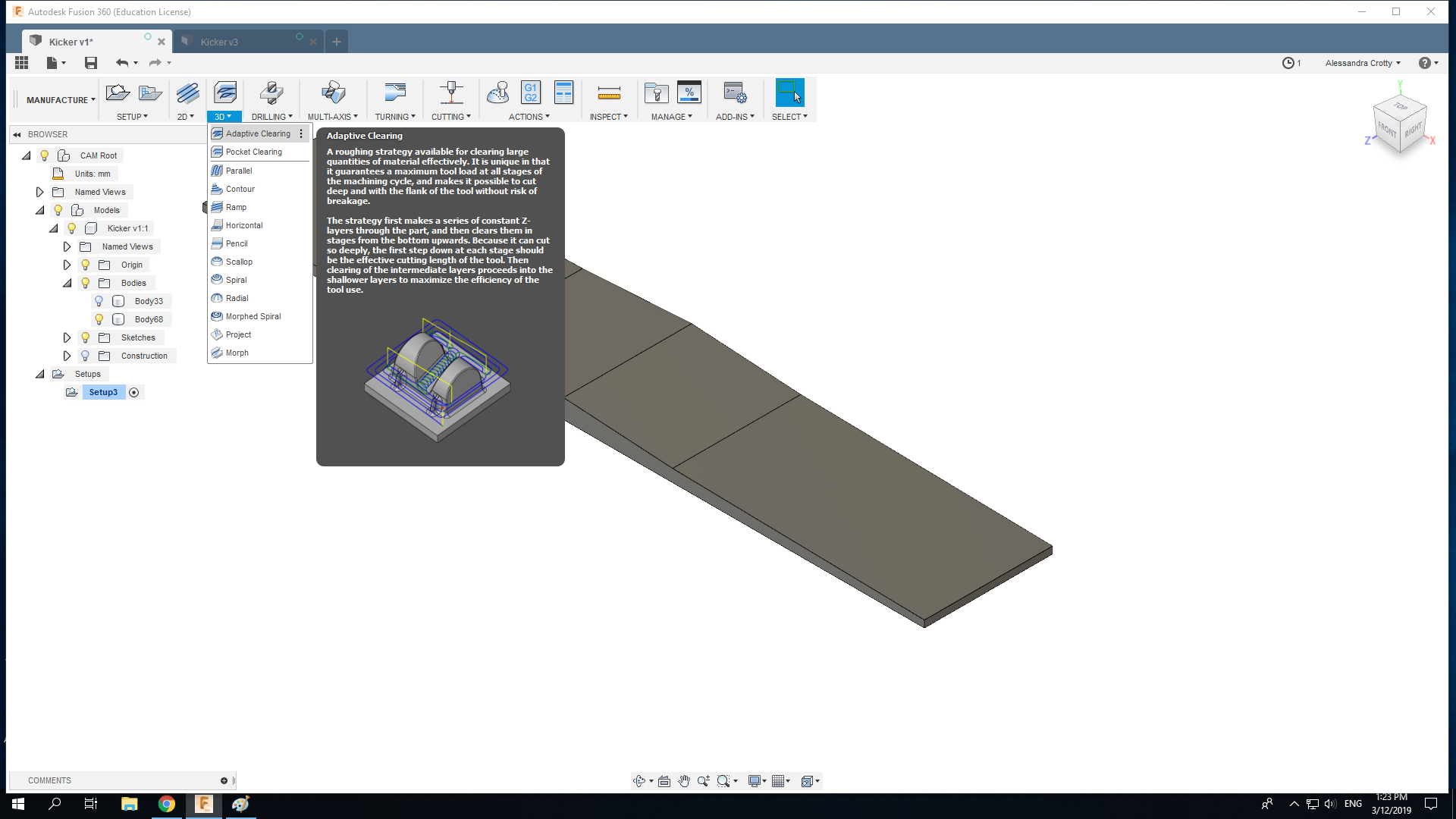
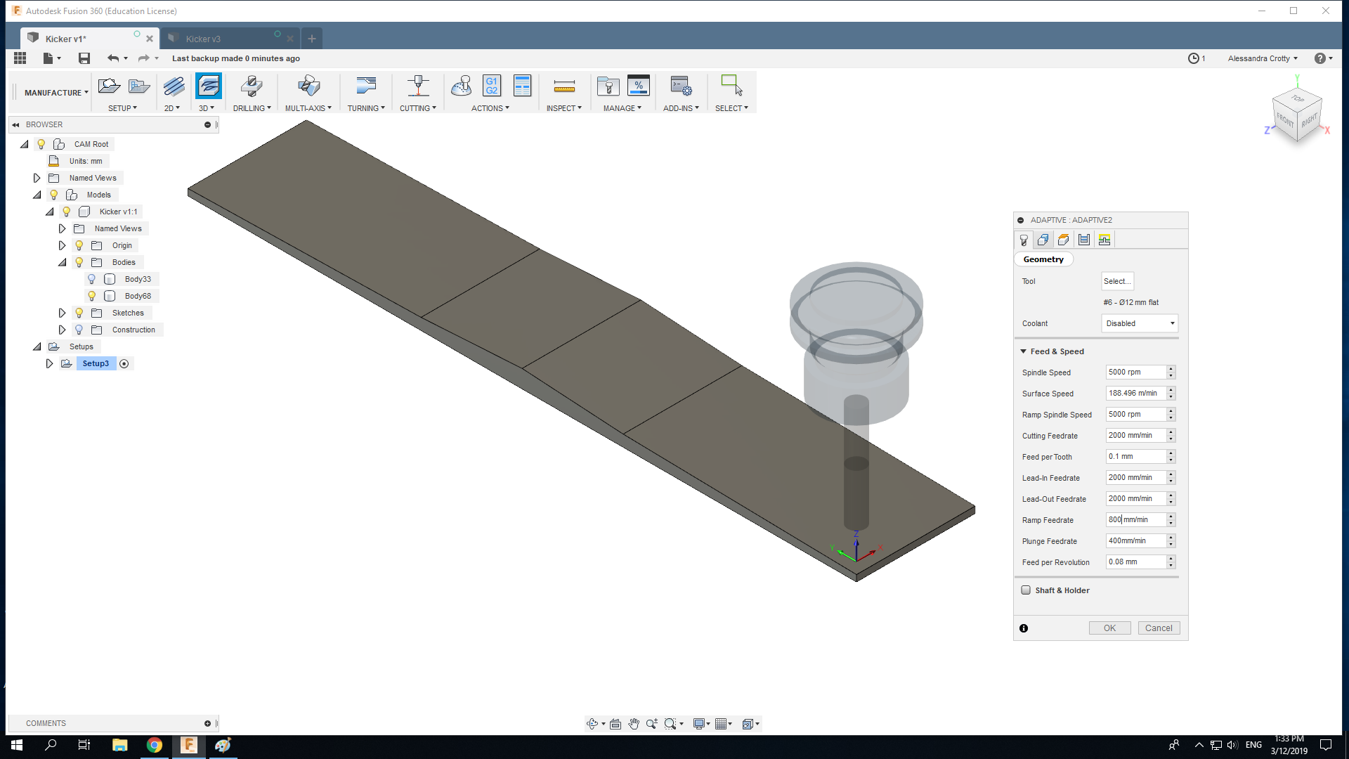
Then the 3D processes Adaptive Cut will be initiatied. We go to 3D > Adaptive Cut in order to initiate the process.
Next you will have to add a new tool.
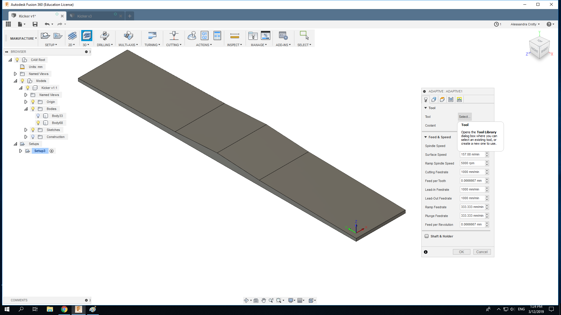
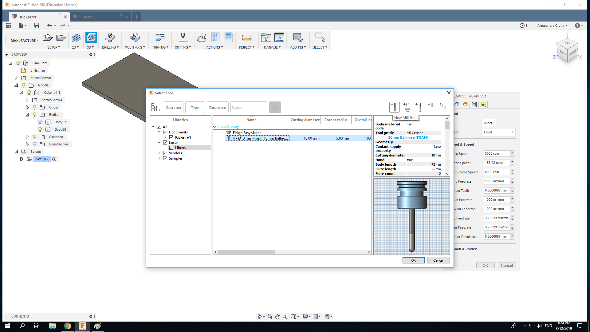
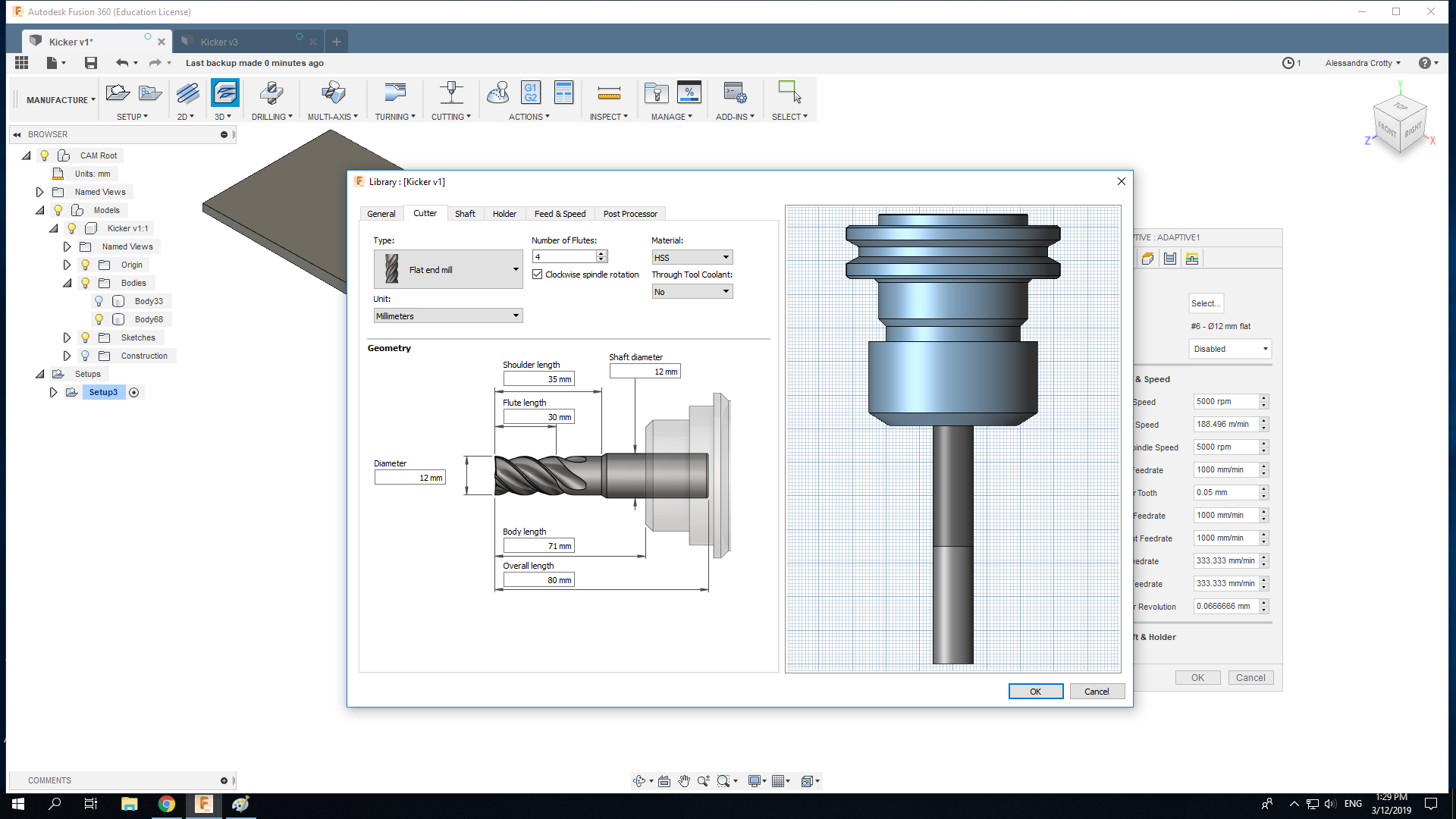
The tool is the Most crytical parameter to consider. When you set up the tool, make sure that the body and flute length are correct. Next set the feed speed and the plunge range.
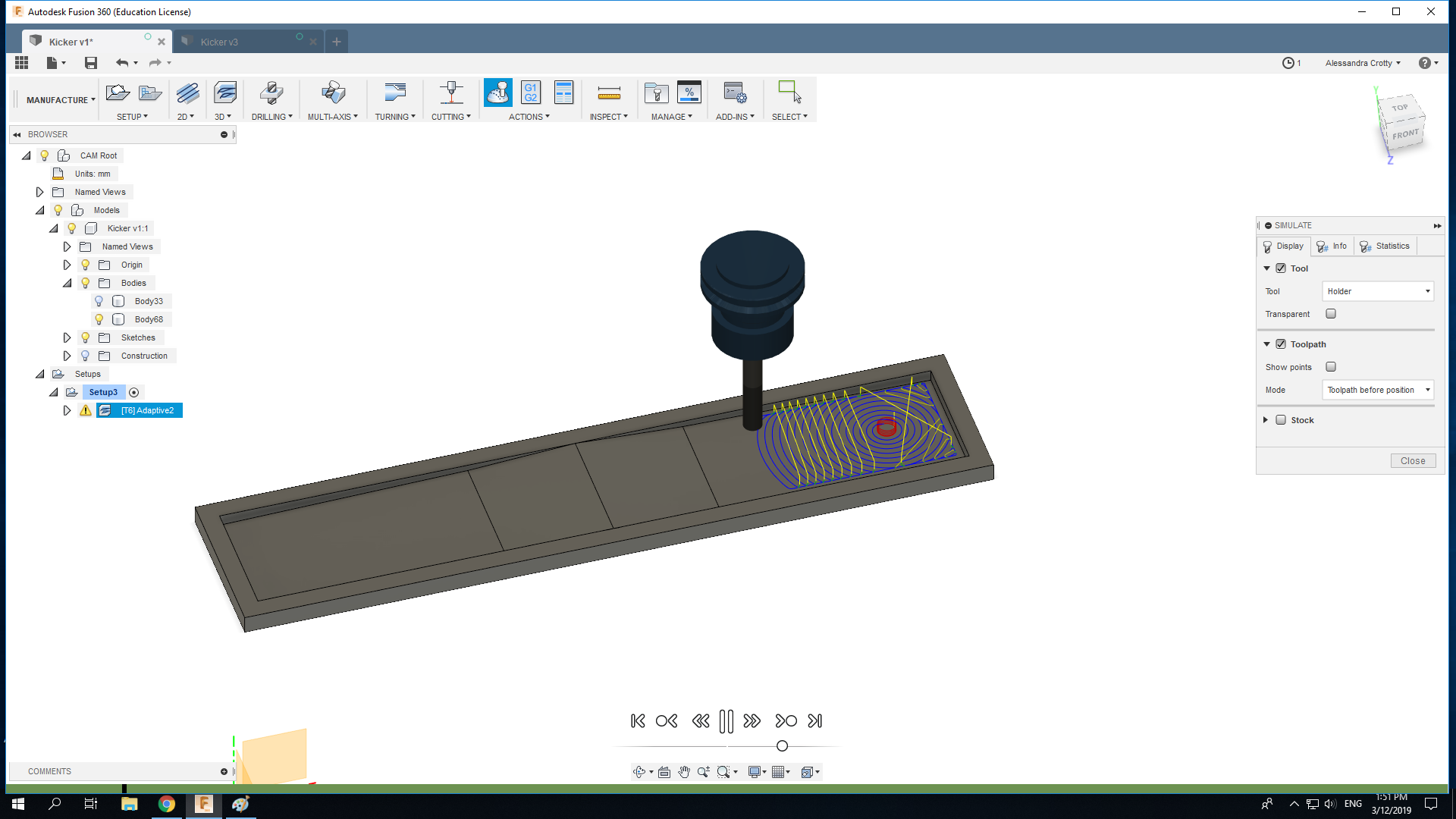
By using the right-click we can simulate the process and see the future work. Make sure that no red flags pop-up.
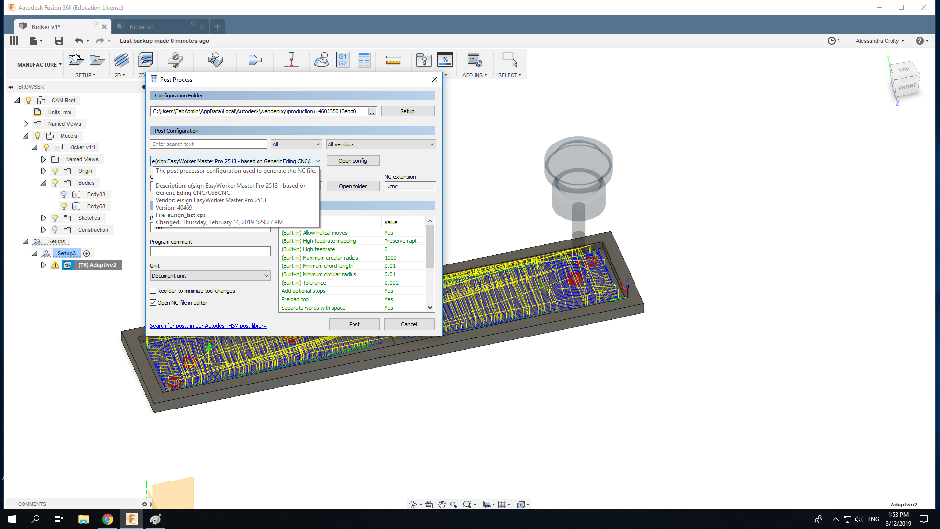
Finally generate the GCODE for your machine and save it by going to post process.
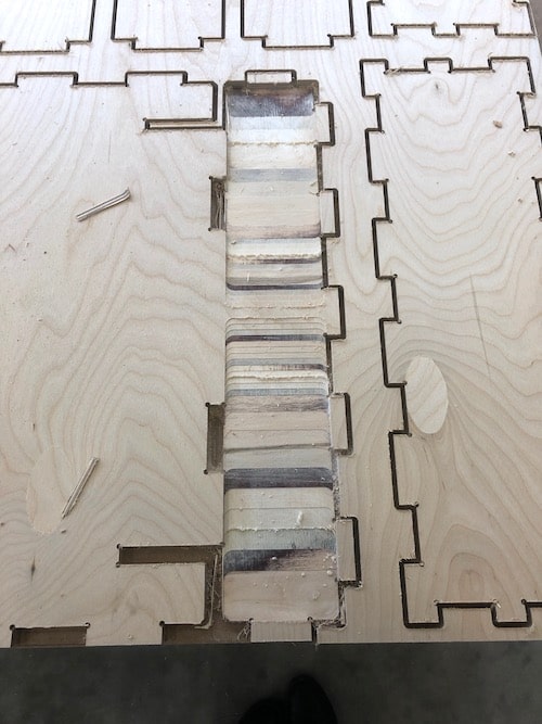
Milling the 3D part
To mill the 3D part I had to set a new zero point.
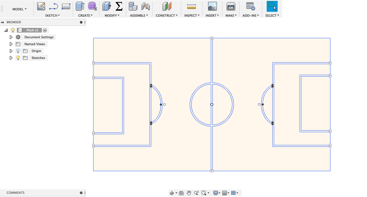
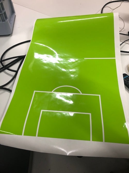
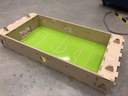
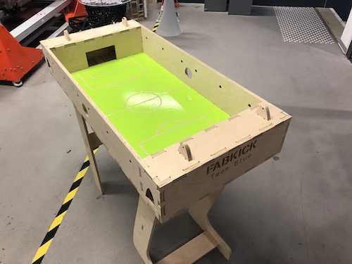
Vinyl Cut the Pitch
I created the pitch with Fusion 360 and exported it into a DXF file to cut it with the Vinyl Cutter. To get a full introduction on how to use the Vinyl Cutter to the Computer Controlled Cutting assignment.
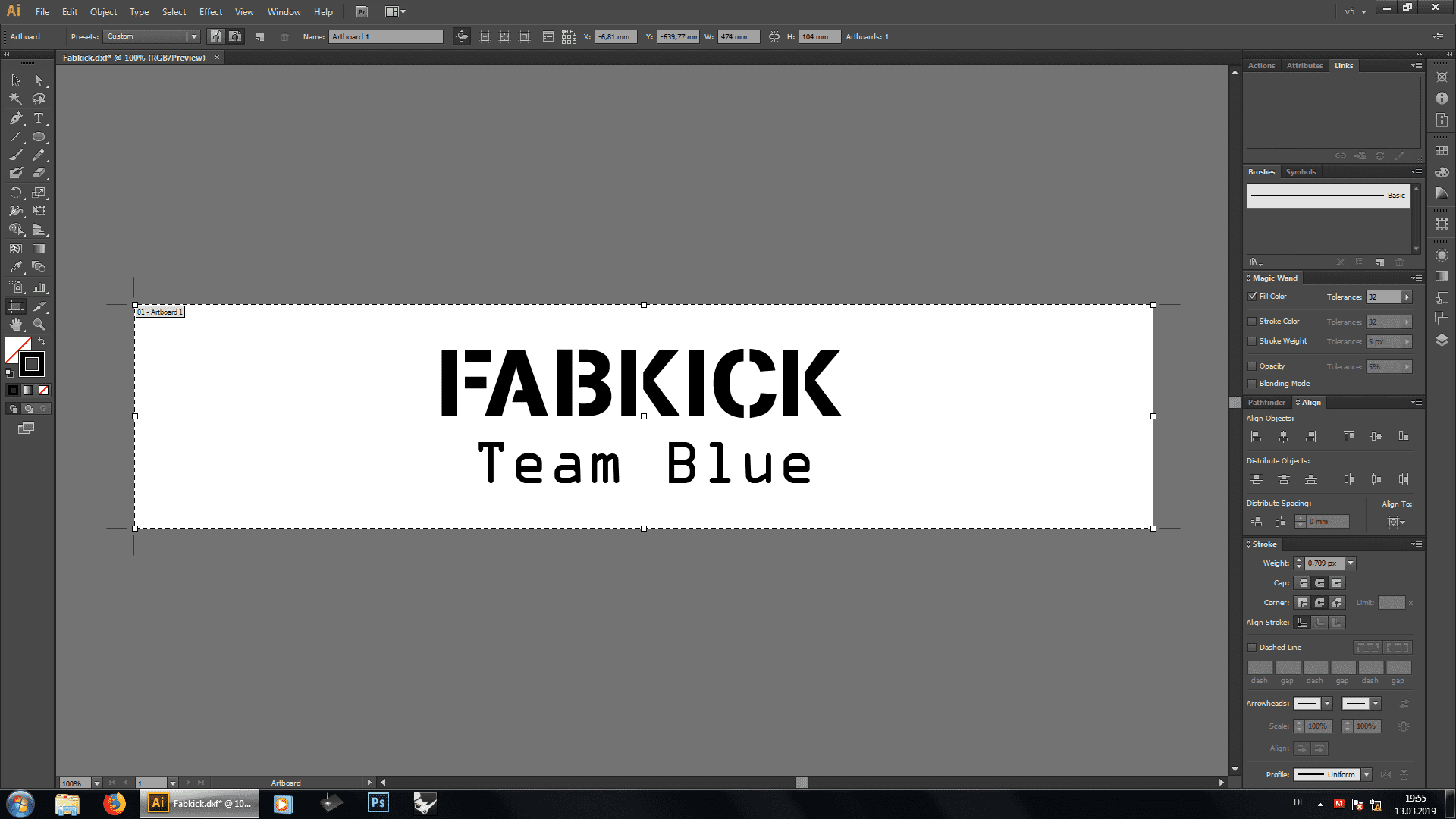
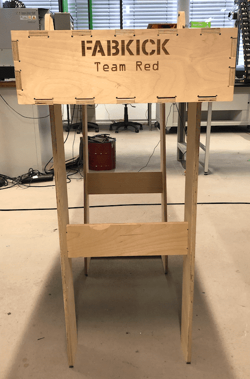
Engraving
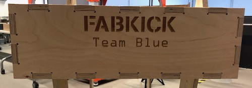
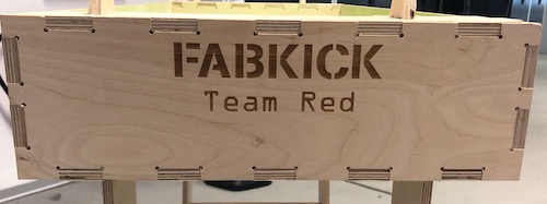
Moreover I used the Laser Cutter to engrave "FABKICK" and "Team Red", "Team Blue" on the sides of the foosballtable. To get a full introduction on how to use the Laser Cutter go to the Computer Controlled Cutting week.
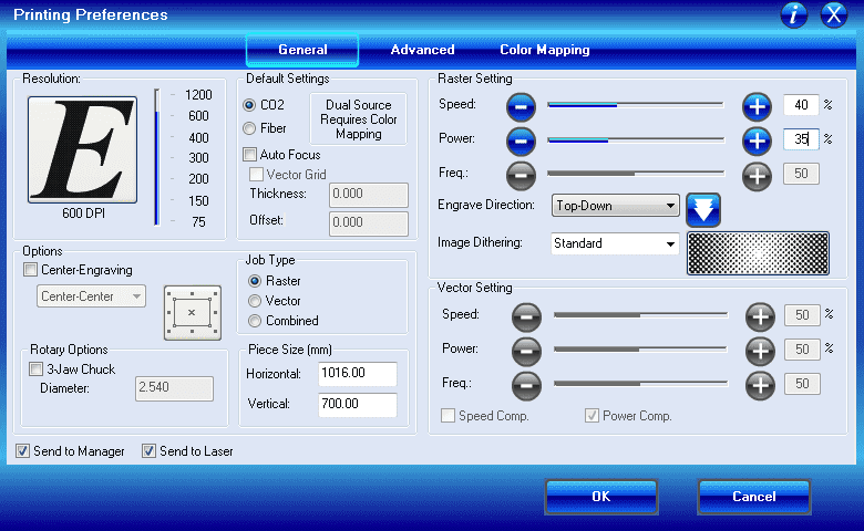
Below you can find the settings with which I engraved on 12mm multiplex.
Assembling
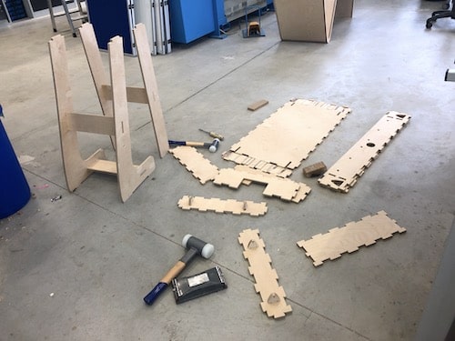
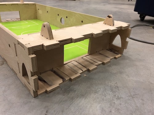
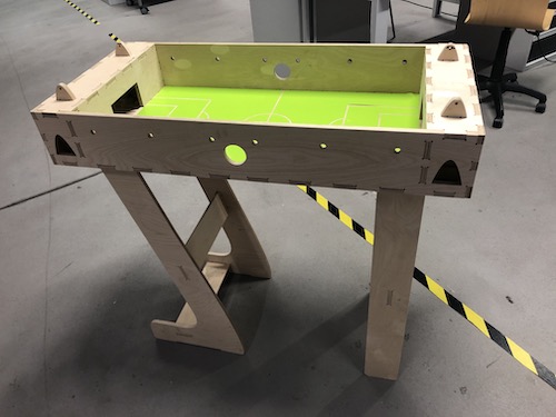
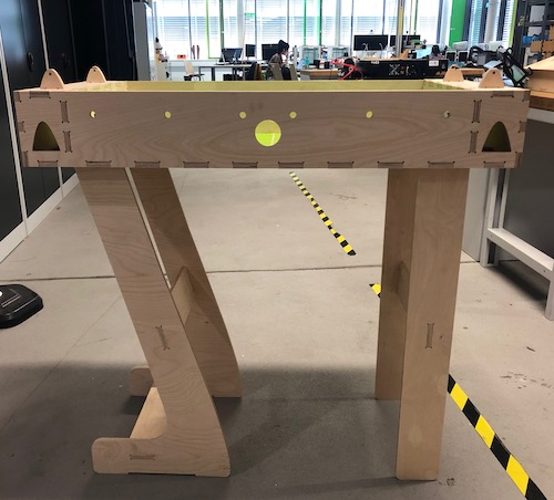
Make your own FAB KICK!
Download Files
DXF-Files
Every single piece of the ModelComplete Fussball Table Design for 250x120cm wood plate
Pitch Design
Engrave FabKick