Final Project
Electric Go-Kart

Idea
After some thinking and research I decided to build my own electric Go-kart. The special thing about the Go-kart is that it will be an electric Go-kart, which is pretty uncommon. Secondly it will contain an automatical steering using a potentiometer to control two brushless motors each one of them mounted on the front wheel. As soon as you turn the steering wheel the mapped values form the poteniometer decrease the speed of the motor on one side and increase the speed of the motor on the other side. Moreover we will use a pedal to drive the Kart. The pedal contains a press sensor, which senses how hard you press the pedal and according to that it increases the speed. As soon as you stop pressing it breakes. This project is carried out in cooperation with Hakan Zayin, another Fab Acadamey student. To get all the information on how to build your own Go Kart, visit also his page.
Applications and Implications
To get more informations on how we started planing the project go to the Applications and Implications assignment.
Project Development
To get more informations on how things were going two weeks before the project endet got to theProject Development page.
Invention, Intellectual Property, and Income
To get more informations about the license I use go to the Invention, Intellectual Property, and Income assignment.
Brain Storming & Planning
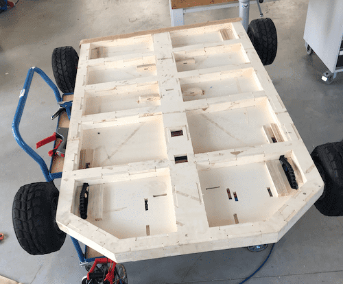
Hakan Zayin and I had some difficulties in planning and designing the Go-Kart. The most difficult part was the planning of the frame because we wanted to keep the Go-Kart as low as possible and on it we had to mount everything (Battery, Motors etc.). We also wanted the frame to be as light as possible so that we could save weight and drive faster. And we were also already aware about the fact that we would drift a lot with our automatic steering control.
Hakan Zayin and I had to split the tasks. I was responsible for the steering, the seat, the joints for the wheels and motors, as also creating the code to drive the motors.
Steering
I started to make the steering during the Wildcard Week, since I made a composite out of it. To read about the first steps go to the Wildcard Week assignment.
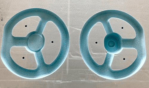
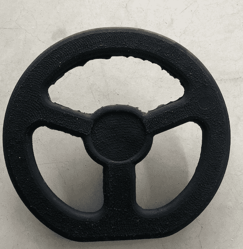
After creating a beautiful robust composite, I decided to cast the steering wheel in silicone to get a nice grip. I used the CNC Machine to create the mold for it. The entire proceedure took very long, since I had to cast multiple times and also do a finishing cast with a brush. To prevent the silicone from flowing through the foam I brushed the mold with acrylic and sprayed it with silicone spray. Unfortunately, this didn't help and I still had to destroy the mold to remove the steering wheel.
For the first two castings I used ProtoSil RTV 245 silicone. The mixture is 100A:10B by weight or volume and is cured at room temperature. To get more infromation about the modling and casting process go to the Molding & Casting assignment
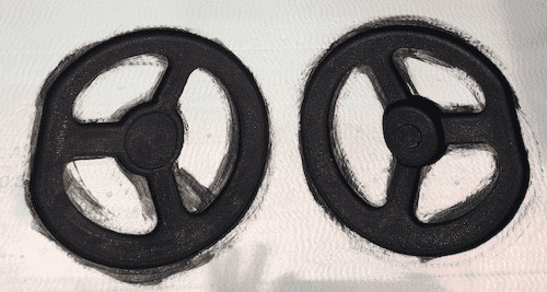
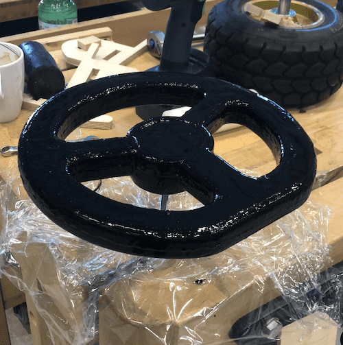
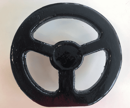
For the last painting I used a different type of silicone: Ecoflex™ 00-30. The mixture is 1A:1B by weight or volume and is cured at room temperature.
Always remember that when casting rubber or composites it is very important that you do this in a well ventilated area. Moreover make sure you wear protective goggles, long sleeves and rubber gloves (only vinyl gloves) to minimize contamination risk.
I used AltroColor 5036 black to paint the silicone. To speed up the curing process, I also placed it in the oven for 2 hours at 176°F/80°C, which reduced the curing time to 3 hours.
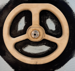
Moreover I also created the streeing wheel holder using the CNC Machine. To get more informations on how to operate the CNC machine go check the Computer-Controlled-Machining assignment. Everything I did I had to discuss with Hakan as he was responsible for the frame structure and had to add the holes for the joints to fix the steering wheel holder. This part is also goingt to be covered with jute and epoxy resin.
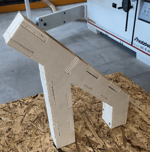
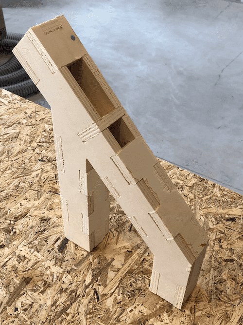
It took a while to find the right steering mechanism. The first thought was to attach a steel rod to it and have some gears to limit the transmission ratio. The potentiometer would then have been attached separately, also with a gear.
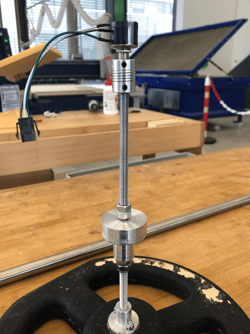
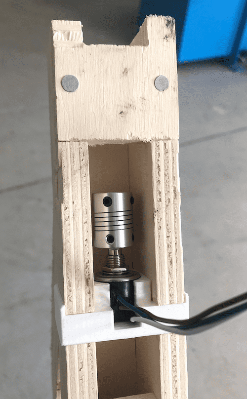
But then I decided to use a threaded rod. This would move the steering up and down, but the transmission of this movement was so small that you couldn't feel the steering wheel going up and down. All I had to do was to create an attachment for the potentiometer that would allow it to go up and down but not rotate. To limit the rotation of the steering, I used two locknuts. I also decided to limit the steering to a maximum of two turns.
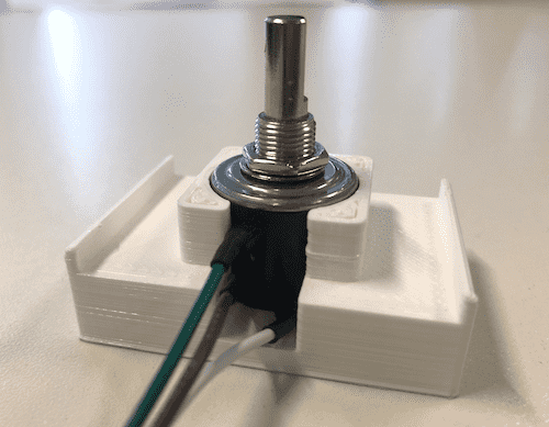
Potentiometer Attachment
Since the steering mechanism is quite unusual, I had to find a way to attach the potentiometer to it. The potentiometer must be able to move up and down without any problems. This is with what I came up with:
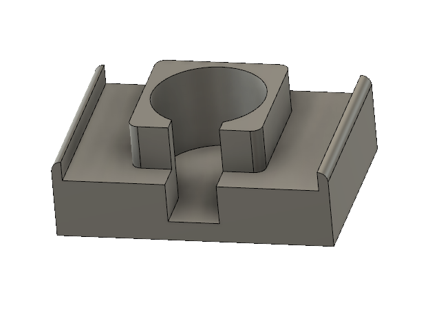
Since it would have been difficult to mill this part, I used the 3D printer. For more informations on how to use a 3D printer go to the 3D Scanning and Printing week.
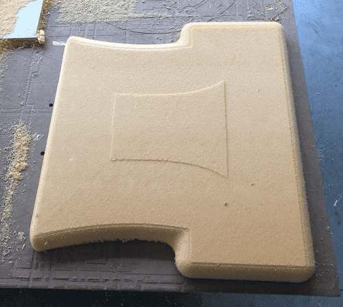
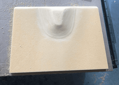
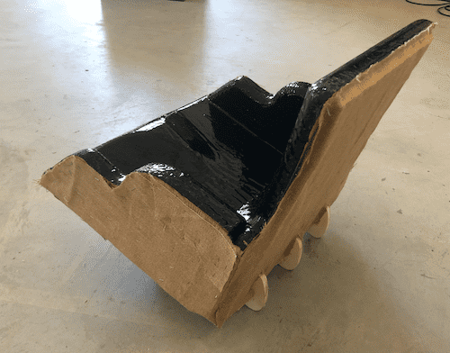
Seat
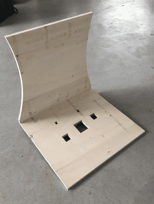
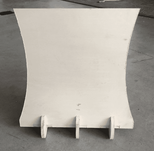
For the seat I used poplar plywood to get a good base and then on the top I applied foam to it produce a comfortable seat. In addition, the seat is very light as the materials are not very heavy. Then I covered it with silicone to make it look nice.
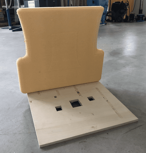
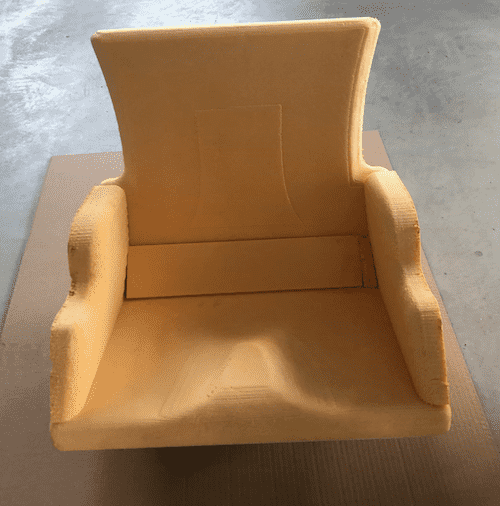
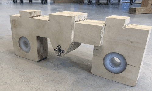
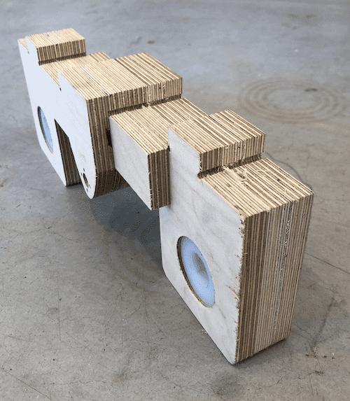
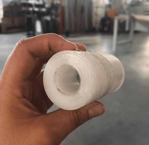
The seat had to be adjustable for everyone. The mechanism I was thinking about was the same as the head of a CNC machine. I used pipes out of aluminium, Pom and a flushing rod to move the seat. I treated the aluminium and the pom on the lathe.
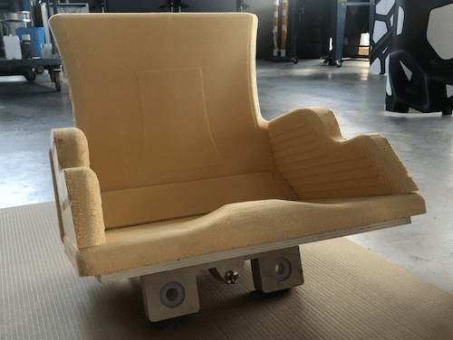
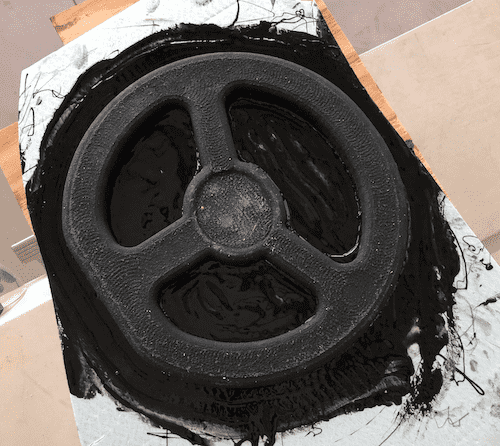
Then I finally covered the seat with silicone.
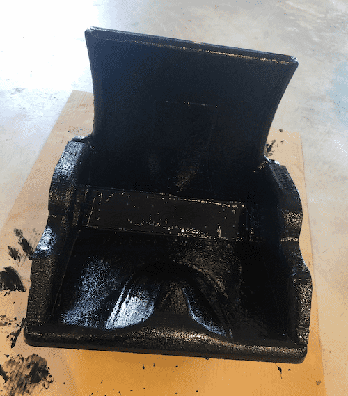
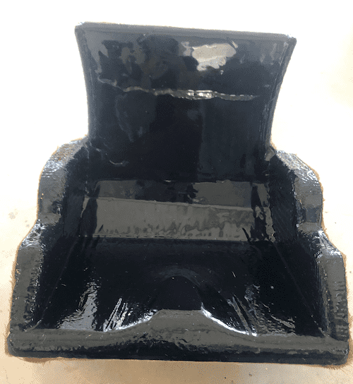
Lastly, I applied jute and epoxy resin to the poplar plywood part of the seat to make it more robust and secure. I even collored the epoxy black to make the seat look whole.
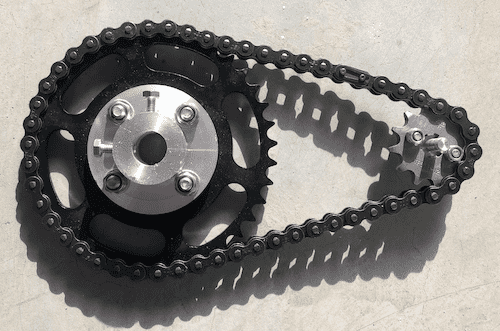
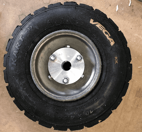
Motors and Wheels
To attach the motos and the gears we made some aluminum parts. I also made the connections for the motors to mount them on the frame. Then we measured the distance with the chain between the two gears to make the hole in the perfect place on the frame. The distance is 177mm.
For the wheel and the steal rod we also created some aluminum parts with the lathe.
Testing the Motors.
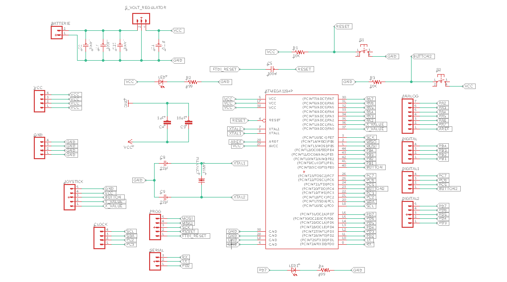
PCB
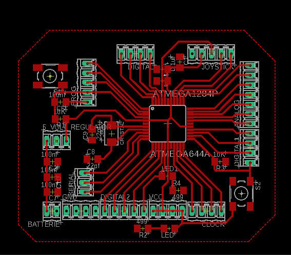
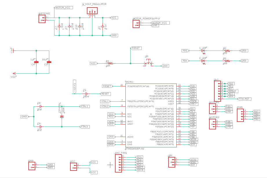
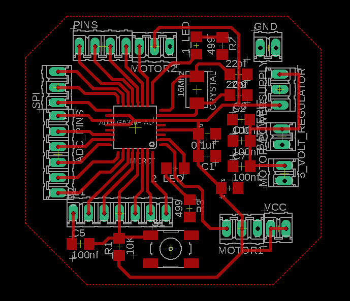
I used the two PCB I made during the Networking and Communications week. To get a full introduction on how to make a Schematic and Board Layout with Eagle go to the Electronics Design week. To read more about how to generate the G-Code and how to use the Roland Mill go visit the Electronics Production page.
Code
The code is based on the code I wrote during the Networking and Communications assignment.
Slave Code Driving Motors
This code receives the mapped values from the pedal and the potentiometer, with which it drives the motors according to the movement of the steering.
#include <Servo.h>//Using servo library to control ESC
		#include <Wire.h>


#define LED 4

int left_servo = 6;
int right_servo = 3;
int potentiometer;
int flex;
int Kl = 1;
int Kr = 1;
int val1;
int val2;

Servo Lservo;  // create servo object to control the  left servo
Servo Rservo;  // create servo object to control the right servo

void setup() {
  Wire.begin(11);
    Wire.onReceive(receiveEvent);
    pinMode(LED,OUTPUT); // set LED pin as an output
    Serial.begin(9600); //for debugging
    Serial.println("Initializing Left Servo"); //for debugging
    Lservo.attach(left_servo);
    Serial.println("Servo Begin");
    Lservo.write(1023);
    delay(2000);
    Serial.println("You should hear a beeping sound ");
    Lservo.write(534);
    delay(2000);
    Lservo.write(53);
    Rservo.attach(right_servo);
    Serial.println("Servo Begin");
    Serial.println("Initializing Right Servo"); //for debugging
    Rservo.write(1023);
    delay(2000);
    Serial.println("You should hear a beeping sound ");
    Rservo.write(534);
    delay(2000);
    Rservo.write(53);
    Serial.println("The ESC will play a tone.");
    Serial.println("Reciever is ready");
    digitalWrite(LED, HIGH);   // turn the LED on (HIGH is the voltage level)
    delay(1000);    // wait for a second
    digitalWrite(LED, LOW);    // turn the LED off by making the voltage LOW
    delay(1000);
}

void loop() {
delay(100);
}

void receiveEvent () {
  while (0 < Wire.available()) { // the same thing as in serial
  potentiometer = Wire.read(); 	// read potentiometer values, range 40 to 250
  flex = Wire.read(); 	// read flex values
  Serial.println (potentiometer);
  Serial.println (flex);
  // if the steering is in the middle, both motors run at the same speed.
  if (potentiometer < 155 && potentiometer > 135) {
        Kl = 2;
        Kr = 2;
       }
	   // When steering right, the left motor rotates at a higher speed than the right motor.
     if (potentiometer < 136 && potentiometer > 90 ) {
        Kl = 2;
        Kr = 1;
       }
	   //The complete right turn breaks the right motor, while the left motor rotates at high speed.
        if (potentiometer < 91 && potentiometer > 40 ) {
          Kl = 2;
          Kr = 0;
       }
	   // When steering left, the right motor rotates at a higher speed than the left motor.
       if (potentiometer < 200 && potentiometer > 154 ) {
        Kl = 1;
        Kr = 2;
       }
	    //The complete left turn breaks the left motor, while the right motor rotates at high speed.
        if (potentiometer < 250 && potentiometer > 199 ) {
          Kl = 0;
          Kr = 2;
       }
    val1 = flex * Kl;
    val2 = flex * Kr;
	// write values to the motor depending on flex and potentiometer.
    Lservo.write(val1);
    Rservo.write(val2);
    }
}
Slave Code reading Potentiometer Values
This code reads the values of the flex sensor and the potentiometer and transfers them to the driver's PCB.
#include <Wire.h>

#define LED 15 // define the LED pin
const byte X_value  = A0;   // X input connected to A0
bool auth;
int value=70;                          //create a random value
const int flexPin = A1;                     //set analog pin of flex sensor

byte input = 0;


void setup() {
  Wire.begin();  // join i2c bus (address optional for master)
  Serial.begin(9600); // here we declare Serial at 9600 baudrate for the input
  pinMode(LED, OUTPUT);  // set LED pin as an output
  pinMode (X_value, INPUT);  // initialize X as INPUT
}

void loop() {
readPotFlex();
}

void readPotFlex(){
input = (analogRead(X_value)); //Map the input values from the joystick on analog pin 0 to  correspond to max and min values for the servo output: 180 and 0
value = analogRead(flexPin);                  //read value of flex sensor
//Serial.println (value);
// this part needs to be calibrated
int val = map(value, 420, 530, 0, 180);
// send the sensor Value of x through radio
Wire.beginTransmission(11); // transmit to device 1
Wire.write(input);
Wire.write(val);
Wire.endTransmission();    // stop transmitting
Serial.println(input);
Serial.println(val);
delay(50);
}
Composite
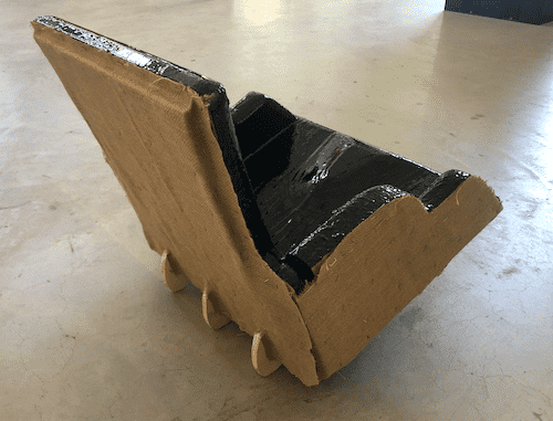
Finally, we assemble the frame with the joints for the wheels and the motors.
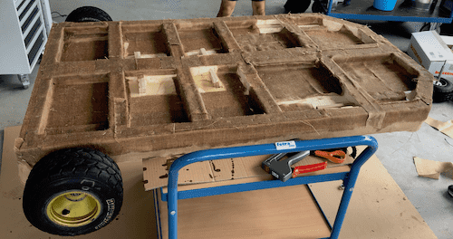
Then we covered it all with jute and epoxy.
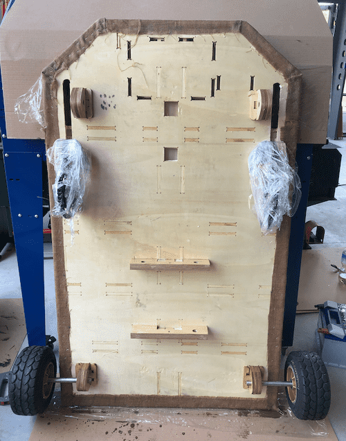
End result:
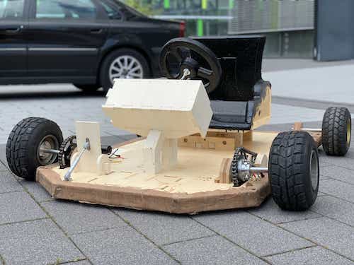
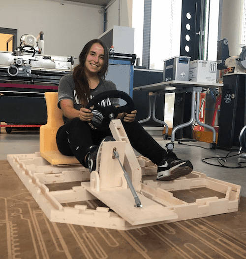
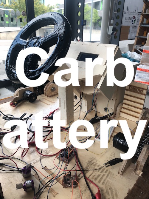
Testing without the seat and steering as we have added a second layer of silicone and these parts need to dry as well as the jute and epoxy.
Unexpectedly one of the ECS and the brushless motors broke. We had a spare motor that we could use, but this motor was much faster and had a higher KV than the one we used, so it was very difficult to drive it at the same speed as the other one. To show that our technique works theoretically, we have made this video below. At the end we have tested every single function of the kart: the authentication, the steering, the gas pedal, the display, the frame and the seat. The video shows how the steering and the pedal work. Each time you turn the steering to the left, the left motor turns off while the right motor continues to turn. The same applies to steering to the right. As soon as you press the pedal, the speed of the motors increases according to the assigned values.
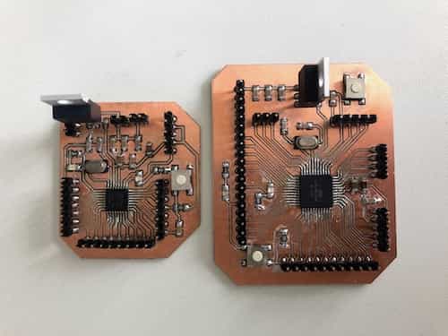
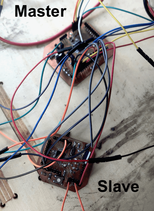
To test the steering and the pedal I used the boards I made in the Networking and Communications assignment. The master transmitted the values from the pedal and potentiometer to the slave, which drives the motors according to the transmitted values. Since you can't see the boards correctly in the video, I took a picture of the construction.
Our future plan is to save some money and buy some proper ECS's and brushless motors to drive the kart on the road!
Download Files
Arduino Code
Slave CodePNG-Files
Master Slave PCBEagle-Files
Master Schematic & Board LayoutSlave Schematic & Board Layout
DXF-Files
GoKart Steering WheelGoKart Joints for Wheel and Motor
Seat made out of Plywood
Seat Holder
Steering Wheel Holder
STL-Files
Steering Wheel MoldPotentiometer Holder
Seat made out of Foam