Final Project
ShooBot
My final project is only the beginning of what there is to come. I have always had a passion for design, art, and fashion. This experience has opened up an entire new world bridging technology and fashion and I CANNOT WAIT to see where this new dimension will take me. My goal in life is to create a brand or be apart of one that disrupts the norms and sparks emotion. Part of this goal is to create solutions to problems I want to solve through design and fabrication. This program has pointed me a little closer to reaching that goal. I have recognized that in todays world starting a clothing brand is not as unique as I would like to believe, however the world of Fashion and Technology has just begun. What if clothing could act like a living thing? Adjust to its wearer and react!!!!! I am getting excited just thinking about it. I am currently looking for other creatives like myself to build this brand with.
I started by prototyping and then made sketches, this may seem backwards to some people, but I like to visualize my concept with something I can hold. Sometimes I think my hands have brains because I can’t always articulate in words what I am doing and why but after I have a creation I analyze it and learn from it. My process is very intuitive.
I took a pre-made shoe and made modifications to it, to try to better understand how I was going to do this.
Phase I: Ideation
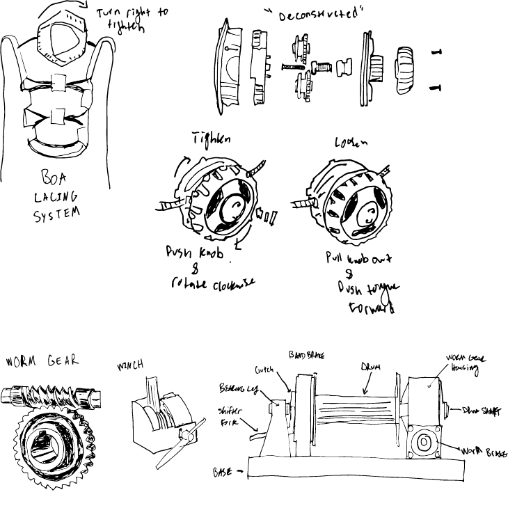
After thinking about how I can make this work on the exterior of the shoe I wanted to the next level and see how I could make this system work in the sole. To do this I need to design how the motor and battery will fit safety in the sole and also how the lacing will be connected. I was very interested in a lacing mechanism I have on a pair of snowboarding boots, that has a “knob” on the front of the laces, that the user simply turns right to tighten and to loosen you push and turn left. I was thinking if I could figure out how to fabricate this I could incorporate a stepper motor somehow inside and control the lacing this way. I was looking into worm gears in addition to a linear rack and pinion system that would take tension off of the motor laces. All three of these mechanisms would be connected in a way that controls the lacing system from one point, opposed to connecting the left lacing side to one side of the motor and the right to the other.
Phase II:Protyping
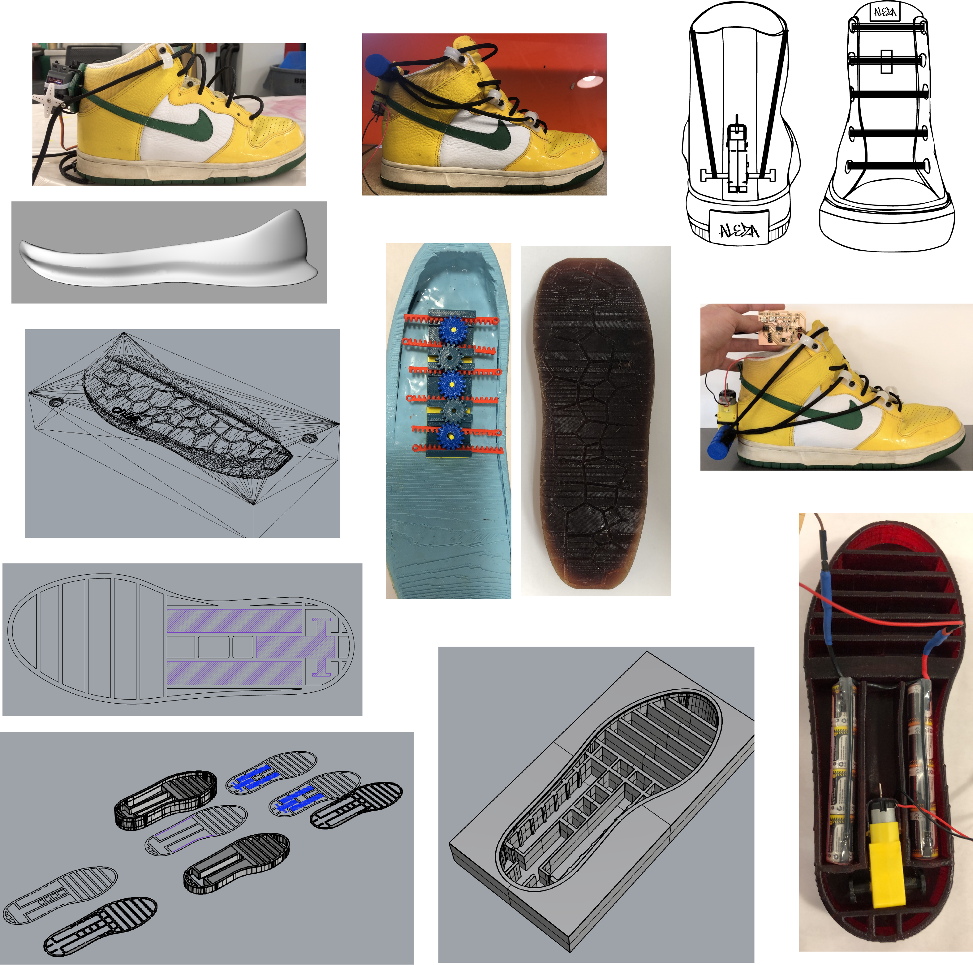
At this step I changed the motor from a servo to a dc motor because I needed more rotation. I also designed 3D printed spools to fit on either side of the motor, to organized the laces as they rotate by the motor. This proved to work very well. However the design is very bulky. At this point I had a working rack and pinion, however when I connected the motor gear the force was too powerful on the racks and they snapped. I think that this mechanism would work well however It needs further modifications and prototyping. I will go back to this idea at some point, but due to time I proceeded with a mechanism I have already proved to work.
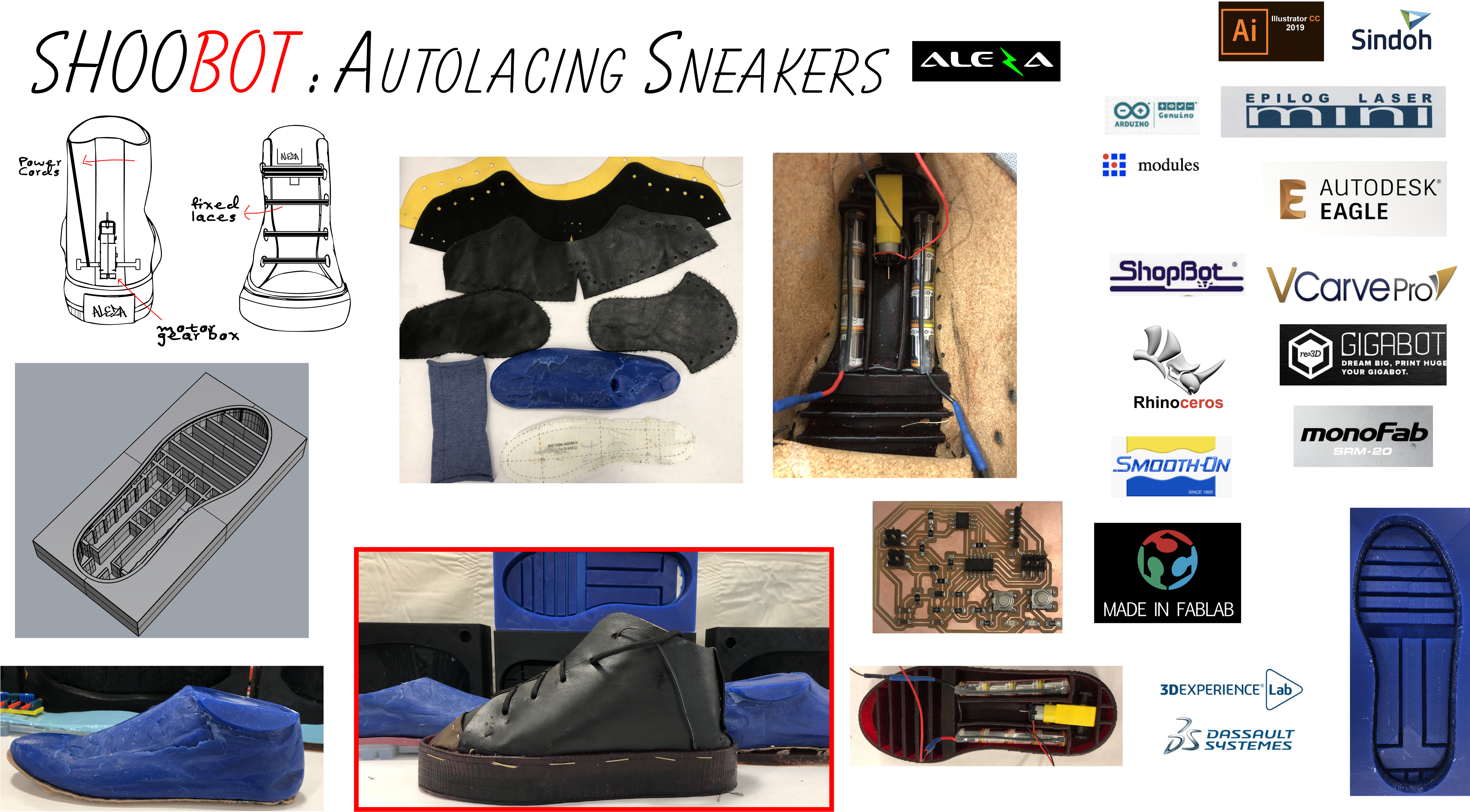
In this sketch I moved the motor lower and scaled the lace spools down. I also added fixed laces to the front that house “power cords that are connected to the motor”
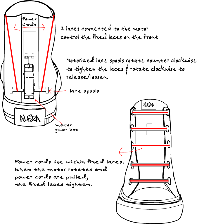
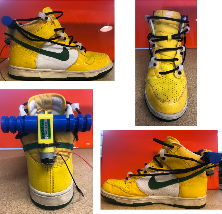
Here you can see the system working with the new motor position and and DC motor board I designed and produced with two buttons, one to tighten and one to loosen. The only problem here is I do not have the motor programmed to hold one it is is the tighten state, so currently both buttons are tightening the laces in different directions.
I am really starting to feel the time crunch and really wish I would have decided on a final project earlier in the course. But I will survive on a few hours of sleep for a week. At this point I needed to decide on how I would go from here. I could either design and package a modular system that any user can affix to their shoe and connect to their laces, turning an average shoe into a “ShooBot”… Or design and produce the entire shoe with the auto lacing system. I am really really motivated by having a brand of my own so I decided on the latter. This decision also allows me to play around with the concept of putting the motor into the sole.
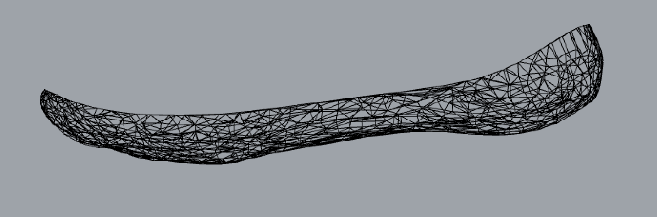
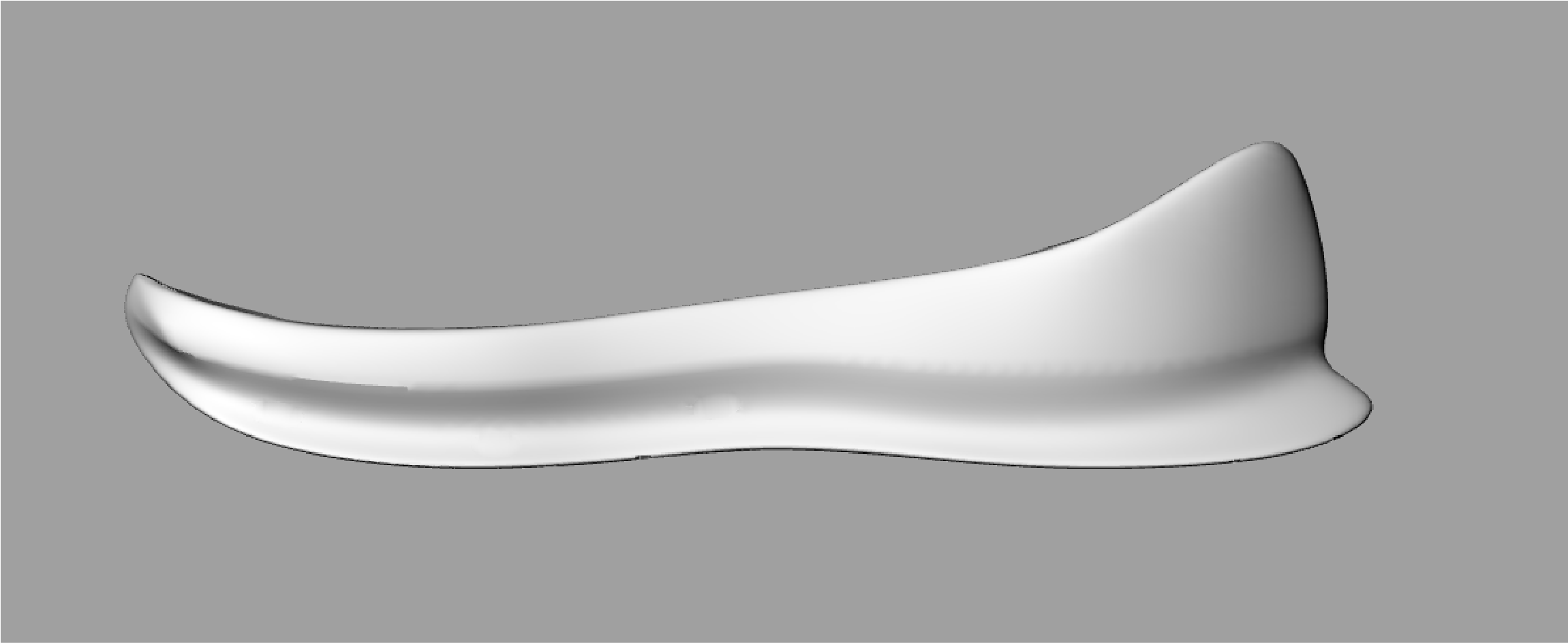 Here is my first sole model. I really like how this ended up looking and I think really illustrates a dynamic sole. The idea was to do a two part mold that fits both the outsole and the insole with the opportunity to access the interior of the outsole (put motor inside) and enclose with the insole.
After getting the design to a form I was happy with I divided it into two halves, inserted within two blocks, using the boolean difference command to create negatives, creating the molds.
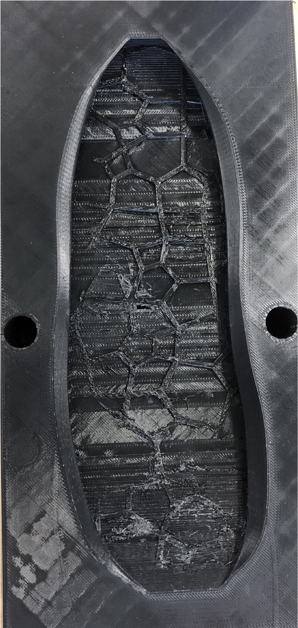
In molding and casting week I produced a sole using VCarve and the ShopBot, which worked very well. So this is proven method. BUt, I have really been wanting to try the large build volume 3d printer, in our lab; the Gigabot3+. To print my sole to scale I needed a pretty big printer (I have big feet), so this is perfect. I prepared my model for 3D printing using SIMPLIFY3D. The program was more complex than that of 3DWox for example, however after a little research it proved to be pretty straight forward. It has a cool manufacturing feature where it tells you how much your print will cost, taking into account the amount of filament used. I printed this using PLA filament and with zero supports, it took 10 hours to complete. I was pretty happy with the result. There were a few funky surfaces, which probably had to do with the tread pattern, it was good enough for me.
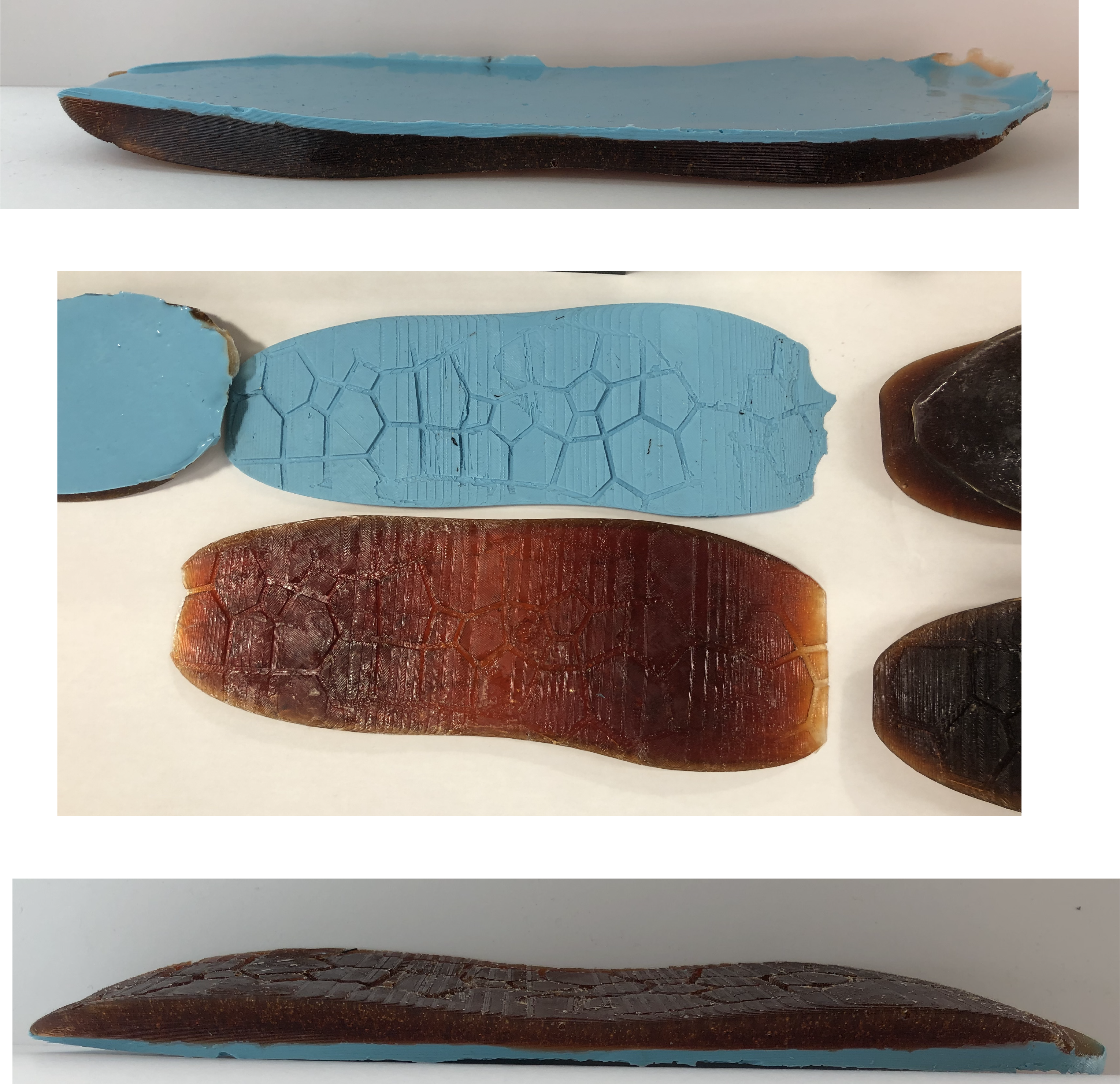
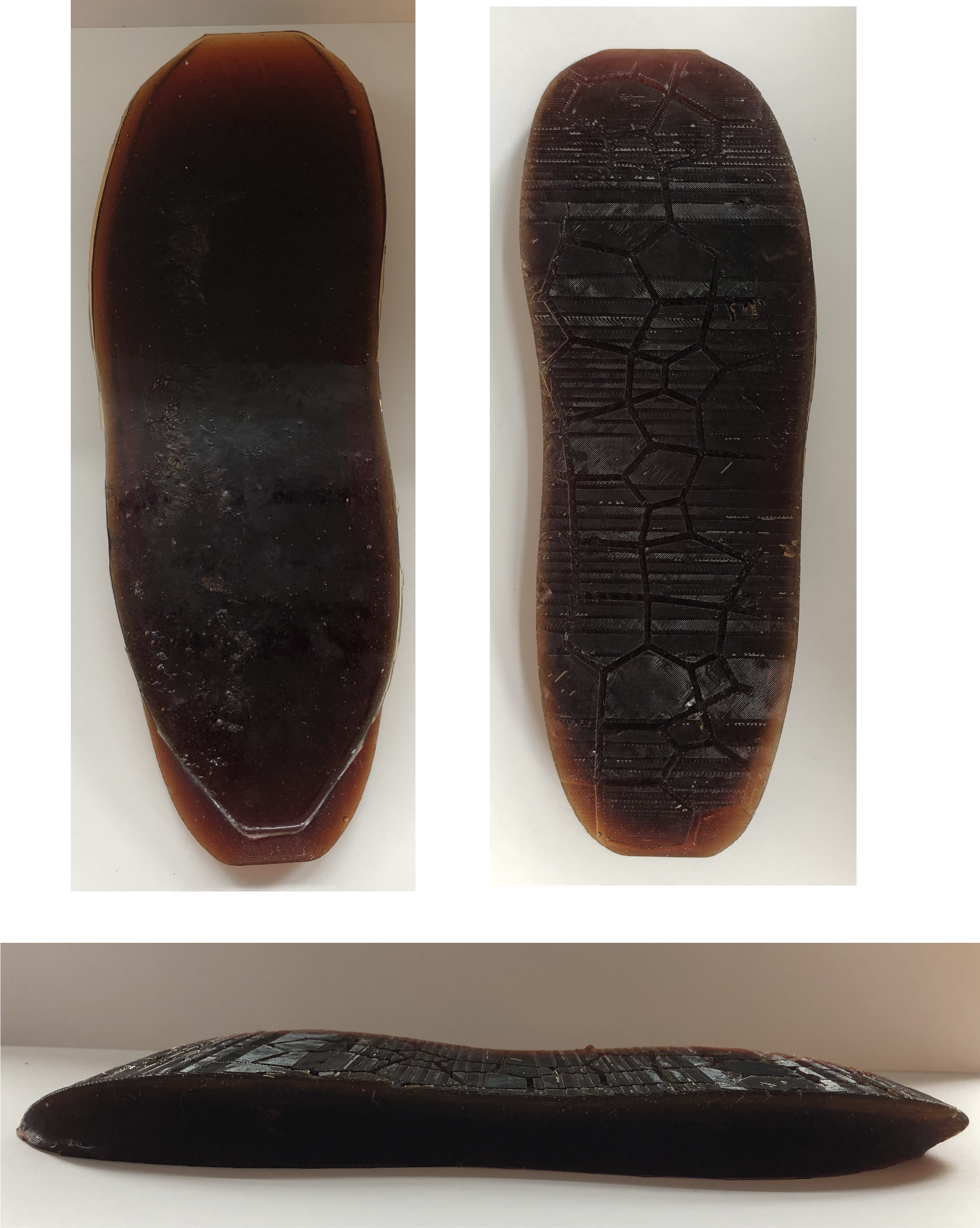
I was very happy with the way both the mold and sole came out. I tested out a few different rubber compounds and decided on using a urethane rubber for the bottom of the sole because of its Shore Value. In addition I used a silicone rubber compound on top of the urethane rubber for a softer cushion for the foot. The urethane rubber was too thick to pour into through the two part molds hole and started curing as I was pouring. I tried using a large syringe to inject the rubber into the mold but the rubber was still too thick. I ended up having to cast the molds separately. This worked out ok because the casts fit perfectly together, however I had to find a way to manually combine them, in order to fit the motor inside and this is a digital fabrication course…
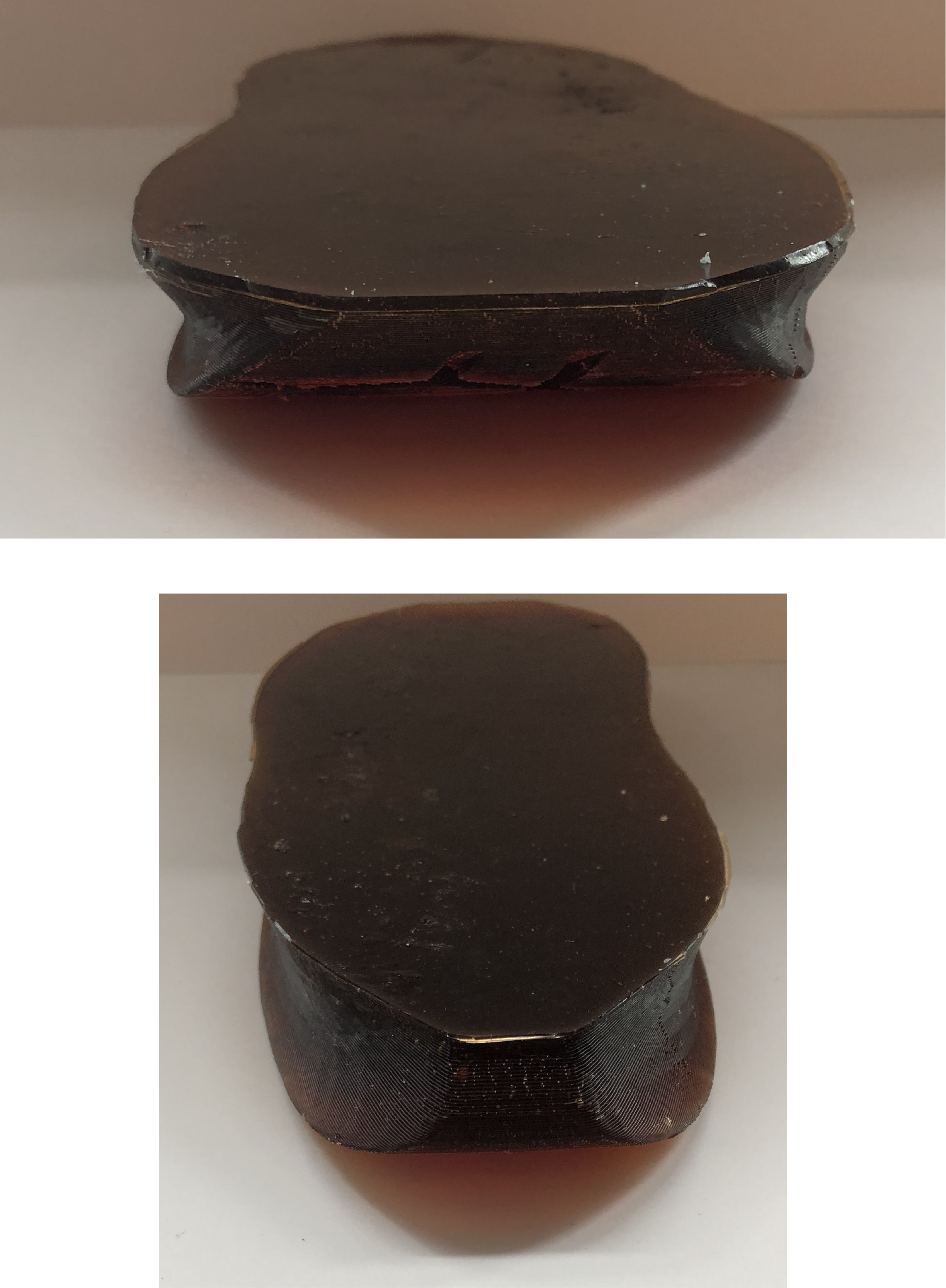
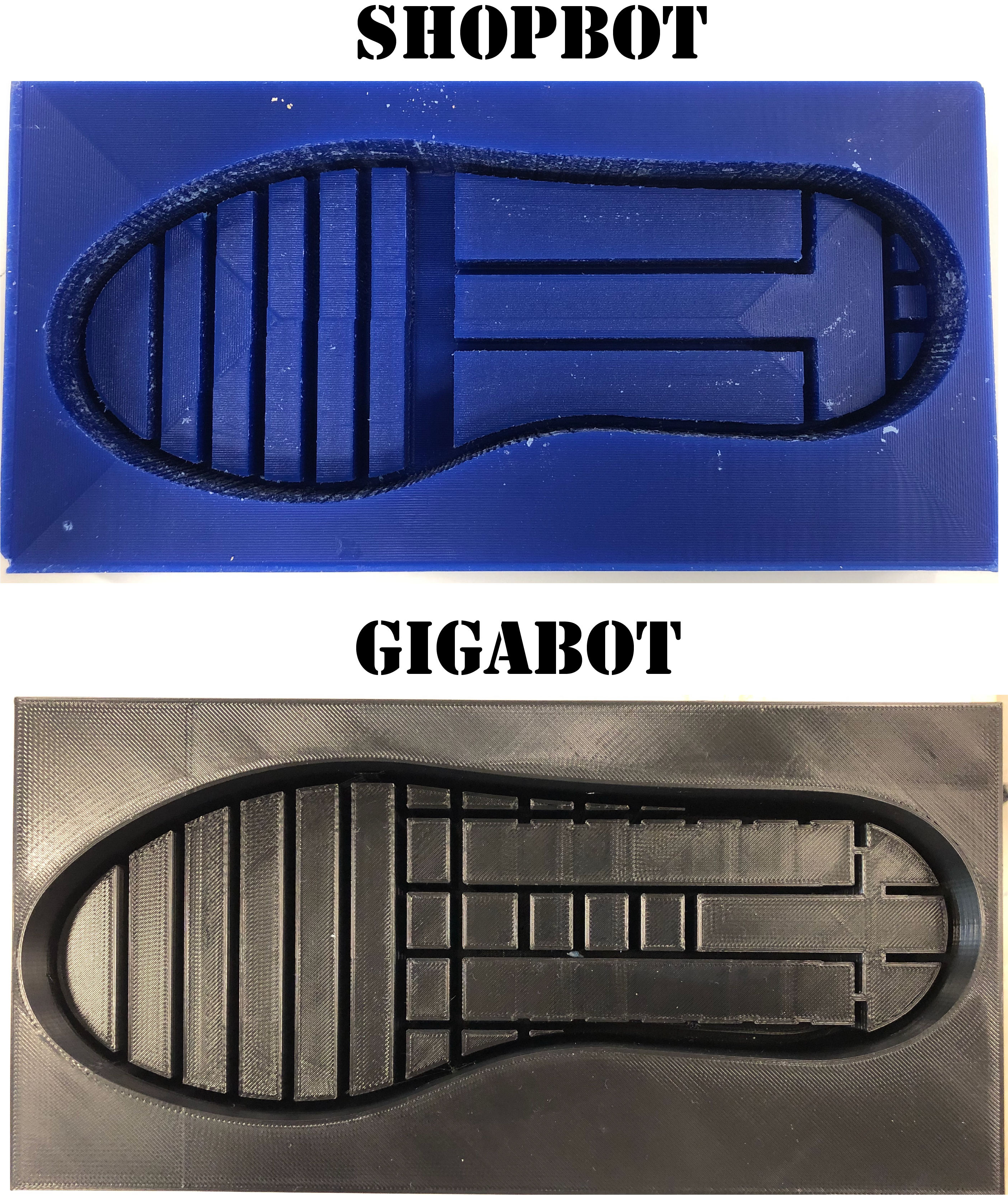
After thoughtful consideration I decided to redesign the entire sole with storage built in for the motor and battery. This was a very risky decision (2 days before my presentation), but it was worth it. The first design is made of meshes giving it an organic, sporty feel (I think), the new design is chunky and rigid, providing internal support for both the wearer and the electronics in the sole. I used both the ShopBot and the Gigabot for this. The first model I designed had cuts that were too small for the 1/8 ball-nose drill bit on the ShopBot so I sent that one on the Gigabot and designed a new model for the ShopBot molds.
WOOOHOOO!!!!
I’m not going to lie I spent so much energy on the sole that once I was ready to design the shoe pattern and construct it all I was shutting down. But, failure is not an option.
I did some research and discovered that all shoe making “starts with the last first.” A Shoe Last is The shoe last is the form used to define the shape of the shoe. The last is critical to the shape and function of your shoe. The shoe last used by the factory will decide the look, fit, and shape of the shoe. It was too late to 3D print one, too late to order one, so I had to get creative. What other resources do I have here that I could pull this off with? .... WAX!! I melted down the machinable wax blocks over a hot plate and with a blow torch. Before melting the wax I lined an old sneaker with scotch tape (the wax did not adhere to this). I strategically chose a sneaker that overtime molded to my foot so the last would actually represent my feet dimensions. After getting the sneaker interior sealed and all of the wax melted (took around 2 hours) I poured the wax and watched it flow into the shape of my foot. This took about a day to completely solidify, but it came out very nice and only needed a little sanding to smooth it out.
I designed a very simple shoe pattern in Adobe Illustrator, choose my material (leather) and used an Epilog laser cutter to cut it out in under a minuet. It took a few trials before getting the right size for my foot. While doing this process I looked into different CAD softwares that are specifically for designing shoes and patterns, which looked sooooooo cool but were very expensive.
Final Product
Overall it is very cool to have an entire shoe built by me, but I am not thrilled with how the final form turned out and will defiantly be redesigning very soon.
The next version will feature, lighter slimmer upper, force sensors, LED’s, wireless controller, and piezoelectricity.
Electronics & Embedded Programming
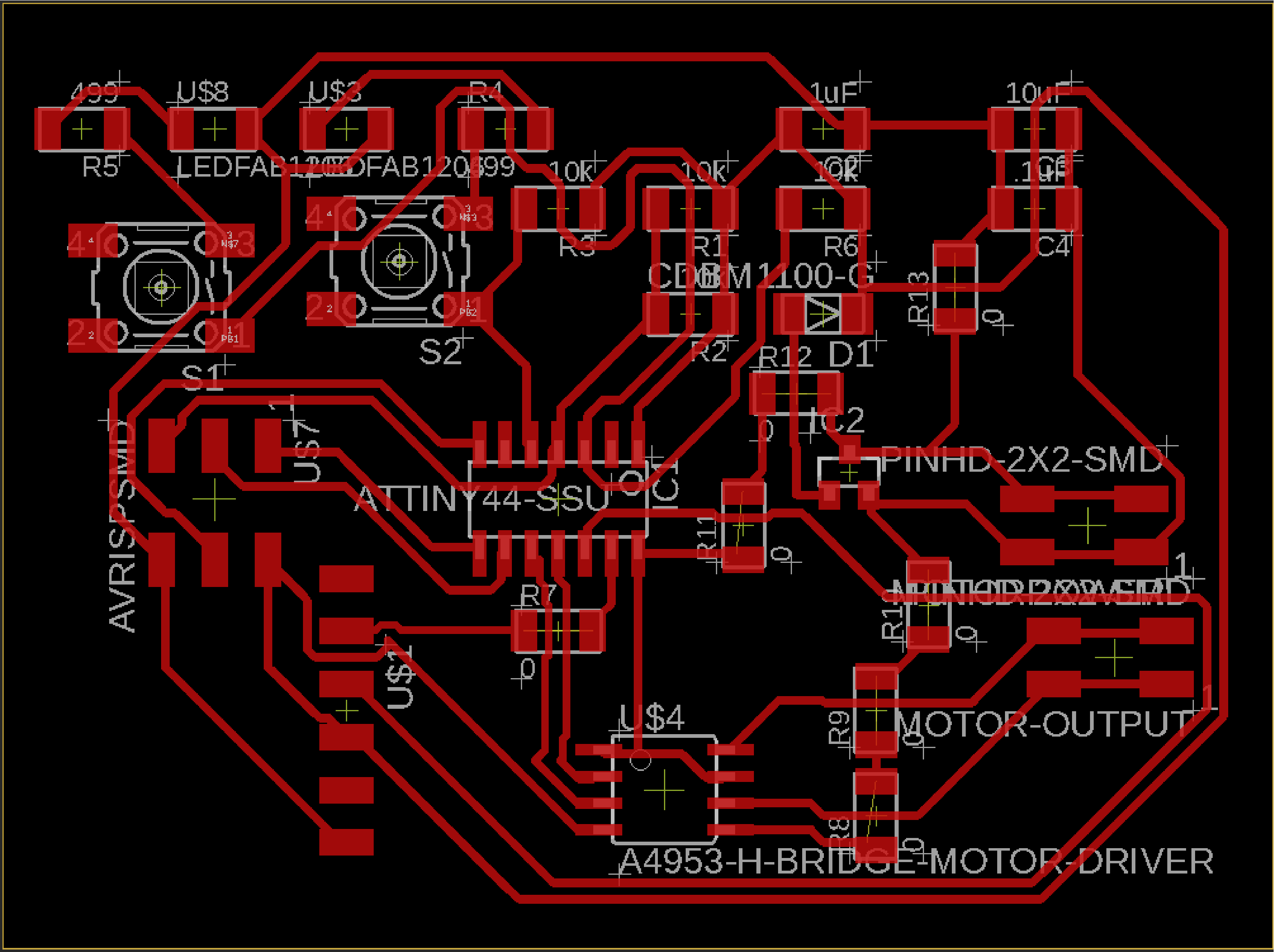
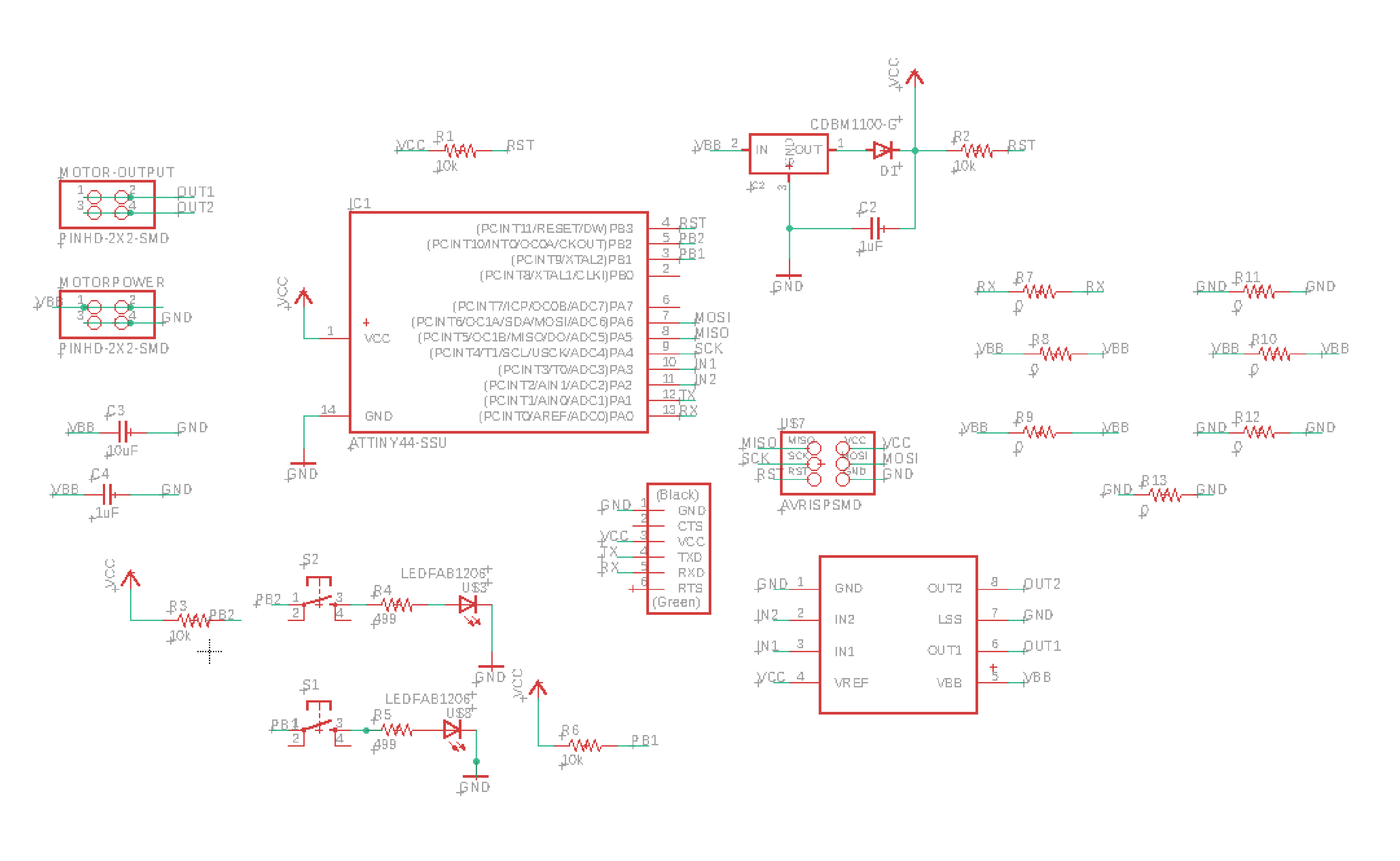
I designed a DC motor board with two buttons connected to LED’s. A red LED is connected to the tightening button and a green LED is connected to the loosening button.
// constants won't change. They're used here to set pin numbers:
const int buttonPin1 = 8;     // the number of the pushbutton pin
const int buttonPin2 = 9;

// variables will change:
int buttonState = 0;         // variable for reading the pushbutton status

void setup() {
  // initialize the LED pin as an output:
  pinMode(buttonPin1, OUTPUT);
  // initialize the pushbutton pin as an input:
  pinMode(buttonPin1, INPUT);
  pinMode(buttonPin2, OUTPUT);
  // initialize the pushbutton pin as an input:
  pinMode(buttonPin2, INPUT);
}

void loop() {
  // read the state of the pushbutton value:
  buttonState = digitalRead(buttonPin1);

  // check if the pushbutton is pressed. If it is, the buttonState is HIGH:
  if (buttonState == HIGH) {
    // turn LED on:
    digitalWrite(buttonPin1, HIGH);
  } else {
    // turn LED off:
    digitalWrite(buttonPin1, LOW);
  }
if (buttonState == HIGH) {
    // turn LED on:
    digitalWrite(buttonPin2, HIGH);
  } else {
    // turn LED off:
    digitalWrite(buttonPin2, LOW);
  }

}
#include <SoftwareSerial.h>

#define rxPin 1
#define txPin 0
#define button1 9
#define button2 8
#define in1 3
#define in2 2

SoftwareSerial mySerial(rxPin,txPin);
void setup() {
  mySerial.begin(9600);
   pinMode(button1, INPUT);
    pinMode(button2,  INPUT);
    pinMode(in1,  OUTPUT);
    pinMode(in2,  OUTPUT);


}

void loop() {
  if (digitalRead(button1)==0){
    digitalWrite(in1,HIGH);
    digitalWrite(in2,LOW);
    delay(1000);
  }
  else if (digitalRead(button2)==0){
    digitalWrite(in1,LOW);
    digitalWrite(in2,HIGH);
    delay(1000);
  }
    digitalWrite(in1,HIGH);
    digitalWrite(in2,HIGH);
}
Testing
Functioning
BOM (Bill of Materials)
| Qty | Description | Price | Link | Notes |
|---|---|---|---|---|
| 2 | (38mm) 6” (152mm) 12” (304mm) Thick Machinable Wax | $24.95 $ | wax | I re-used blocks that our lab purchased for molding&casting week |
| 2.0 lbs. | Econ 60 Urethane Rubber | 27.78 $ | Econ60 | My lab already had this in stock, so I did not need to purchase for my project |
| 2 | Keenstone Upgrade 9.6V NiMH 1600mAh | 14.98 $ | Amazon | |
| 1 | Leather (12”x24”) | 17.96 $ | Amazon | |
| 1 | Hobby Gearmotor - 140 RPM (Pair) | 4.95 $ | sparkfun | Lab had in stock |
| 1 | Hobby Gearmotor - 140 RPM (Pair) | 4.95 $ | sparkfun | Lab had in stock |
| 1 | 10 Feet Paracord | 5.49 $ | Amazon |
See week19 for license information.
Design Files
File above is too large to upload directly
File above is too large to upload directly