4. Computer Controlled Cutting
This week I worked alongside my group to characterize our laser cutter, in addition to making test part(s)that vary cutting settings and dimensions. Individually, I cut something on the vinyl-cutter, designed, laser-cut, and documented a parametric press-fit construction kit, accounting for the laser-cutter kerf, which can be assembled in multiple ways. I have worked with a vinyl cutter before for producing t shirt designs, but never with a laser cutter. In addition, I am new to both machines in our lab.
Laser Cutter: Epilog Mini
 Key Parameters:
    -Laser Power
    -Speed
    -Rate (Laser Frecuency)

    Materials:
    -Polywood
    -MDF
    -Acrylic
Kerf
To begin characterizing the laser cutter it is first important to understand what the Kerf is. Kerf is defined as the width of material that is removed by a cutting process. It was originally used to describe how much wood was removed by a saw, because the teeth on a saw are bent to the side, so that they remove more material than the width of the saw blade itself, preventing the blade from getting stuck in the wood.
Group Findings:
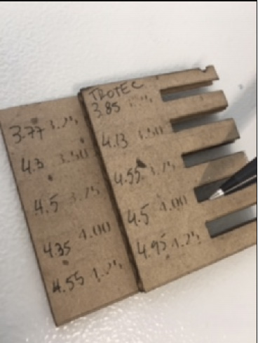
The concept was to make a 2 sloted boards with a small variation in every slot length, incrementing from 3.25 - 4.25 [mm]. After they were cut we measured every slot real size to determine the machines kerf.
| Sloted Board | Theoretical Length | Real Length | Delta |
| 1 | 3.25 | 3.85 | 0.60 |
| 1 | 3.5 | 4.13 | 0.63 |
| 1 | 3.75 | 4.55 | 0.80 |
| 1 | 4.00 | 4.50 | 0.50 |
| 1 | 4.25 | 4.95 | 0.70 |
| 2 | 3.25 | 3.77 | 0.52 |
| 2 | 3.50 | 4.30 | 0.80 |
| 2 | 3.75 | 4.50 | 0.75 |
| 2 | 4.00 | 4.35 | 0.35 |
| 2 | 4.25 | 4.55 | 0.30 |
| Average Kerf | 0.60 | ||
| Estandard Deviation | 0.18 |
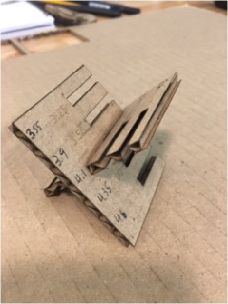
We found that 4 mm (0.15748in) thikness heavyduty cardboard- the best slot to make joints
Parametric Cutout Construction Kit:
I began by doing some research on parametric design. Parametric is a term used to describe a dimension’s ability to change the shape of model geometry as soon as the dimension value is modified.
Parametric modeling uses the computer to design objects or systems that model component attributes with real world behavior. Parametric models use feature-based, solid and surface modeling design tools to manipulate the system attributes. One of the most important features of parametric modeling is that attributes that are interlinked automatically change their features. So it allows the designer to define entire classes of shapes, not just specific instances.
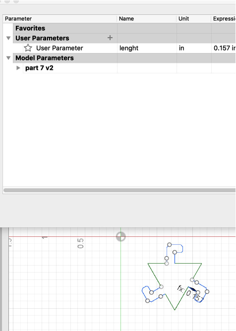
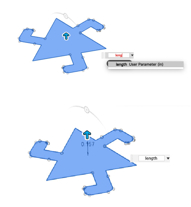
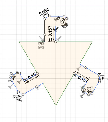
From my research on parametric design software and tools I believe that Rhino has very powerful parametric design tools that I defiantly want to learn. But in the spirit of spiral development, to complete the Laser-cut assignment with time to do something extra with the vinyl cutter, I choose to design my press-fit kit in Fusion360, which I was a little more familiar with. I started with a basic shape: a triangle and then created joint slots on each side. I used the “user parameter” to set the slot distance of my joints equal to the thickness of the cardboard. I think it is really cool that through parametric design techniques there is no need for an adhesive or medium to create a strong connection between joints.
Before using parametric design, to modify a 3D solid, I had to change the length, the breadth and the height. However, with parametric modeling, I need to only alter one parameter; and the other two parameters get adjusted automatically. I made a very basic cutout kit, setting the joints equal to the thickness of the cardboard with a small tolerance. Using the user parameter I set I was able to easily modify the 3 joints in my model by setting one in the beginning.
After I was finished with my cutout shape I exported my file into into Adobe Illustrator, to prepare for cutting. Next I prepared the document settings: making the sheet size L18 x W12, setting the line thickness to <.07 pt (or 0.001in or 0.25mm). Anything thicker will be treated as engraving.
Another feature one can use (I did not) is using RGB colors to define line colors. Red: (255,0,0): engraving, green: (o,255,0): inner loops cuts, blue (0,0,255): outer loops cuts.These colors can then be mapped to laser settings and print order in settings.
After double checking all of the settings I turned on the machine, turned on the compressor, turned on the fan, setup the print (actually sending the print), make sure my job was loaded in the printer, pressed “Go”
  Lasercutter settings:
    Cutting:
    - corrugated cardboard 4mm
    - Speed: 60
    - Power: 30
    - Frequency: 1300
    Engraving:
    - corrugated cardboard 4mm
    - Speed: 60
    - Power: 30
    - Frequency: 1600
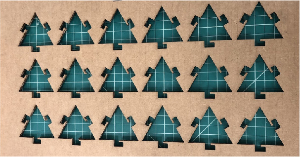
Problem: On my Laser-cut cut sheet above, the nesting of my parts is suboptimal. If I were to do it again I would position my parts to be cut in such a way that it maximizes the amount of material that ultimately becomes a part. For instance I could have utilized a common line, cutting where parts shares a cut line by arranging my parts, so that they have a common edge.
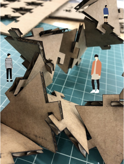
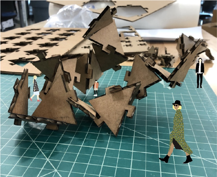
After assembling my kit in multiple ways, I settled on a formation, and tried to discover something from it. I imagined how the space it created could be inhabited on a larger scale. Using Illustrator I image traced, expanded, and ungrouped miniature figures I found online to manipulate them to my liking, and placed them throughout the model photo.
Vinyl Cutting:
        Key Parameters:
        -Force
        -Speed
        -Cut Depth

        Materials:
        -Vinyl
        -Transfer Adhesive
        -Masking Tape
I am a huge fan of the artist Banksy work and have focused some of my own designs to reference his stencil techniques. Banksy is an anonymous England-based street artist, vandal, political activist, and film director. His satirical street art and subversive epigrams combine dark humor with graffiti executed in a distinctive stenciling technique. His works of political and social commentary have been featured on streets, walls, and bridges of cities throughout the world. I didn’t actually realize the impact he has had on my work until documenting this.
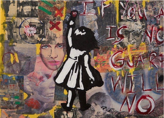
snapshot of a stencil production I created representing a young version of myself, incorporated on one of my paintings
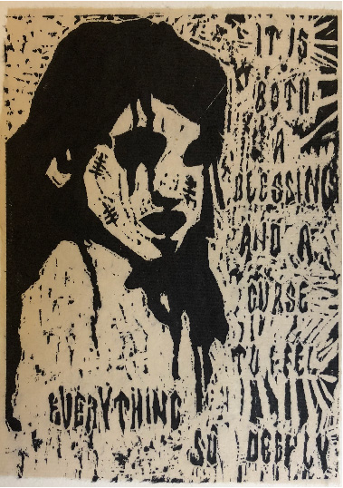
original woodblock print, featuring a self portrait
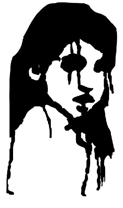
Here is the original silhouette that I carved out of the woodblock. I decided to use this same image to create a vinyl sticker. To create my imagery I reference real photographs and simplify forms into to silhouettes.
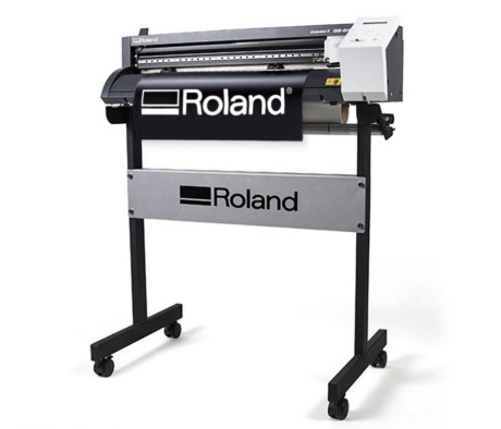
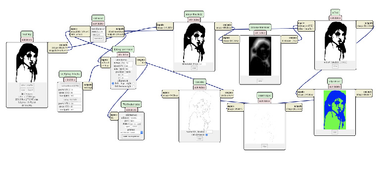
After I was happy with my design I exported my file as a .png file. I used mods to process my png files and send them to the Roland SRM-20 milling machine. Mods is a project lead by Prof. Neil Gershenfeld in the Center for Bits and Atoms that allows you to connect devices (modules) through a user friendly web interface. Most machines come with their own programs that you can install to connect your computer and device, but these are rarely simplified. Neil has made this a lot easier by connecting modules that do very specific tasks. In our FabLab I use mods to send all my files to a device.
Note: It is vital to Start the mods server and to open a local/server program in order to preform a task with mods. Once I was connected to the server I selected open server programs from the drop down menu. Next I found the machine I will use, Roland GS24 and below selected “cut png.”
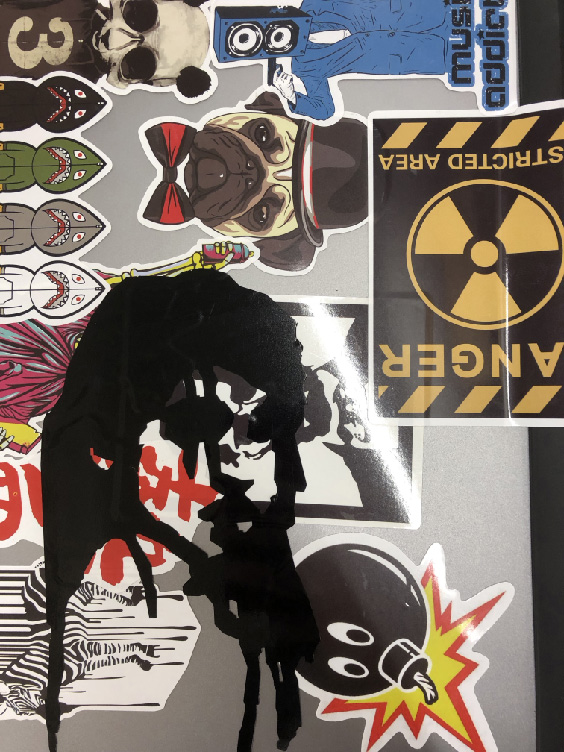
Just as Banksy leaves his tags all over buildings and walls I like to leave my mark on surfaces through stickers. here can you see my new sticker added to my laptops collection.
Just For Fun
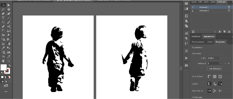
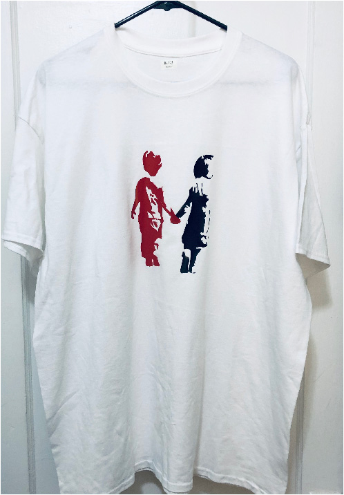
One of my passions developed through my art is fashion. I like to put my own touch onto any clothing I own. Below is another silhouette graphic that I created in Adobe Illustrator, of two young children holding hands. The graphic is apart of a collection I have titled: R.I.P. Youth. I originally designed the image as one art-board, but decided I wanted each figure to be a different color of vinyl so I split them into two and made two stickers that I then combined at the end.
Our lab did not have clothing vinyl in stock so I thought I would try it out with what was available (sticker vinyl). One of my hobbies is running a small streetware clothing line so I own heat press (with the amount of pressure and heat it provides this should work) IT DID!!
Design Files
Useful Links
There are many parts of the FabAcademy are new to me, which is why I am so drawn to the program, because of my love for learning. However it is nice to bring a skill from my own background into the mix. This week was especially fun for me when I got to design and made a t-shirt. For some reason at first the parametric construction kit was just not clicking with me. I have designed using CAD before, however mostly designing by eye and intuition and somehow making the design work. However this is no way of working for fabrication. Many of my classmates have backgrounds in engineering so with a little help I figured out how set parameters within the program, making the whole process come together.
I ended up finding parametric design so cool that in the “Make Something Big” unit I ended up using the techniques I learned.