7. Electronics design
“SIRI” sculpture I made using found circuit boards and clay

This week I worked alongside my group using test equipment in your lab to observe the operation of a microcontroller circuit board. In addition, I redrew the echo, added a button and LED (with current-limiting resistor), checked the design rules, make it, and tested it. It was my first time ever designing a circuit board, however Neil made it easier by providing us with his Hello-Echo board to reference.
I began by downloading the hello-world board
Programs
Next I downloaded Autodesk EAGLE and booted it.
Libraries
After I downloaded the Fab-Library. I have a Mac so it the file path is: /Applications/EAGLE-8.#.#/lbr/. After downloading the library I installed it into Eagle. I did this by going to the top toolbar and selecting the “Library” followed by, selecting “use” and opening the .lbr file. It is important to make sure that the little circle to the right of the Library is green.
For components not in the Fab Lib: Eagle Libraries. You shouldn’t need this but in case.
Schematic
A schematic in electronics is a drawing that represents a circuit. It uses symbols to represent real-world electronic components. I followed a tutorial for adding a button, LED (with current-limiting resistor).
Components:
- Attiny44 x1
- 20 Mhz Resonator x1
- LED x1
- 499 Ohm Resisitor x1
- 2x3 ISP Header x1
- 10k ohm Resistor x2
- 1uf capacitor x1
- Push Botton x1

Board
After I finished I completed the schematic, I routed the traces, using the traces using yellow connection guides that EAGLE provides.

Design Rules
Next I checked my board for errors:
- Navigate to tools menu
- Click DRC
- Load fab.lbr
- Click check
I encountered quite a few errors my first go-around, however it was very helpful in my learning process. Once I got a no error message I wanted to play around with the design of the routed traces.
I had a-lot of fun adding my own artistic flair to the board. I like sharp edges and chaotic designs and I tried to represent that in my design. In the future I defiantly want to work on manipulating the final board design in novel, creative ways.
After I was happy with the design I exported my board to prepare for milling.


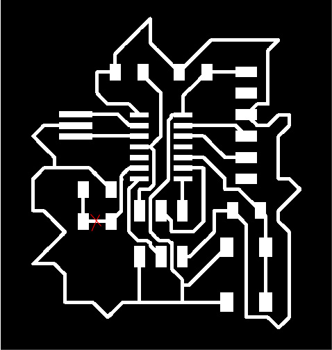
Fig 01. I hid all layers except the top to get my boards traces.
Fig 02. I hid all layers except the dimension layer to get my boards interior.
Fig 03. Export images in monochrome color as a .png file.

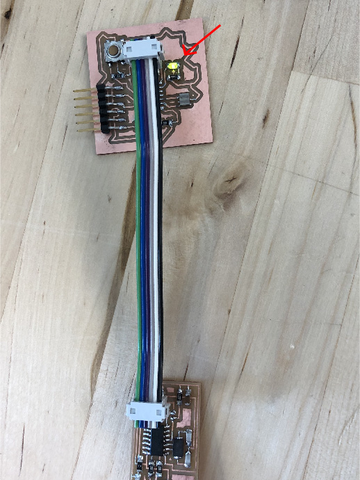
my board after soldering components
Testing
Testing Hello-Echo Board
To test my board I uploaded code in Arduino IDE using the ISp programmer I created in week 5. I modified an example test provided by Arduino to program the LED and the Push Button:
The first time around the test was unsuccessful and my LED did not blink. I used a multimeter to check the continuity and voltage and everything seemed good. Then I checked the diodes and discovered it was not properly measuring so I removed the solder and the component and noticed there was an un- needed line.
After cutting out the line and re-soldering the components, the LED blinked when the button was pressed!!!!
see week 9 for the detailed Arduino process
Osciloscope
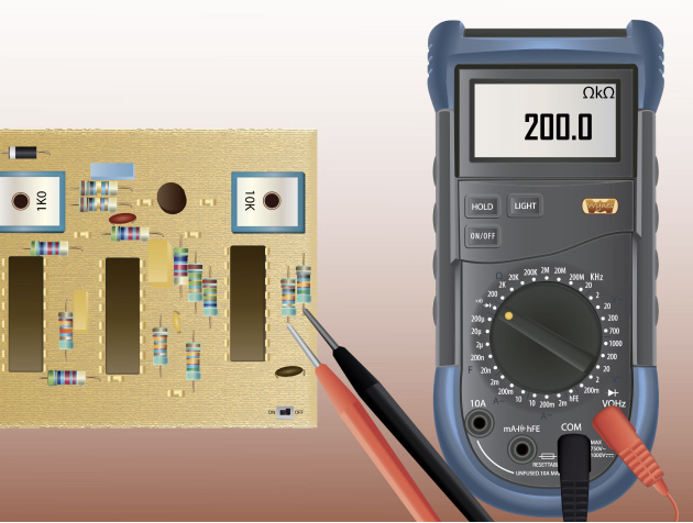
I have now demonstrated using a multimeter to troubleshoot errors on my circuit boards. However when this device cannot provide all of the information such as frequency, noise, amplitude, and other characteristics that might change over time, you can use an Oscilloscope.


Testing the resonator: the display should read 20.0 MHz if it is measuring correctly. We got it to read 20.0 MHz once but there was no graphic display.

Testing out the LED
Design Files
After completing this weeks assignment, I gotta say I feel pretty cool. I know this task is very simple for what it is, however being a rookie to electronics it is very rewarding to accomplish a task I never thought I could do. I always feel like electronics are magic and now it is kind of like I am learning some of the Magicians tricks.
