14. Networking and communications
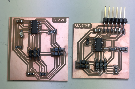
This week I designed, built, and connected wired or wireless node(s) with network or bus addresses. In addition, sent a message between two projects. I chose to do the asynchronous serial bus. Thus, I designed 1 node (x2) boards and 1 bridge board.
a·syn·chro·nous
/āˈsiNGkrənəs/
“of or requiring a form of computer control timing protocol in which a specific operation begins upon receipt of an indication (signal) that the preceding operation has been completed.”
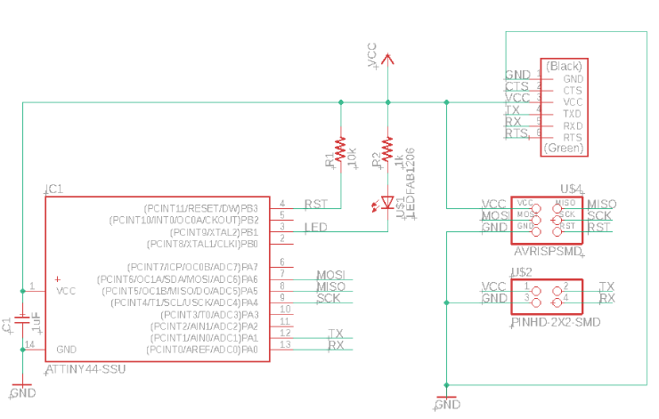
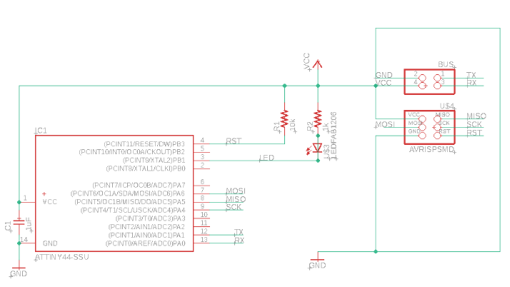
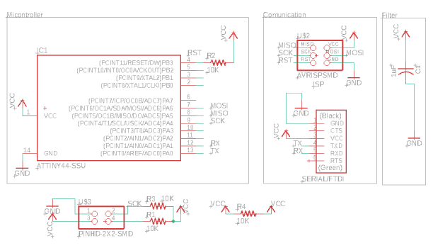
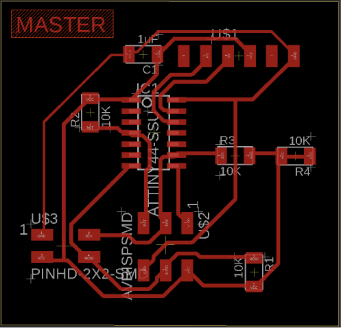
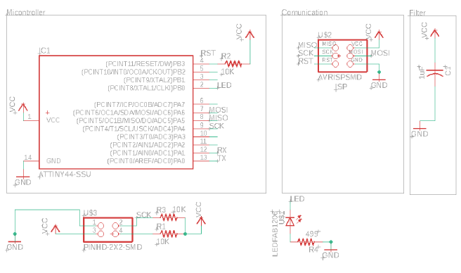
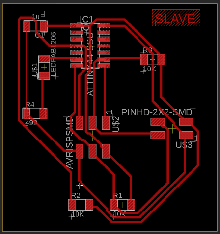
I started by creating schematics. I used Neils bridge and node boards to reference the components he used and then designed my own schematic to help me understand the theoretical side of the boards, describing how the components are electrically connected. After this I moved to designing the PCB layouts, which is all about the physical placement of parts and copper.
Components
HELLO 44 BUS BRIDGE
-
1uF CAPACITOR (1)
-
ATTINY44 (1)
-
10k Resistor (1)
-
1k Resistor (1)
-
LED (1)
-
PINHD-2X2(BUS)(1)
-
AVR-ISP (1)
-
FTDI-1x6 (1)
HELLO 44 BUS NODE(S)
-
1uF CAPACITOR (2)
-
ATTINY44 (2)
-
10k Resistor (2)
-
1k Resistor (2)
-
LED (2)
-
PINHD-2X2(BUS)(2)
-
AVR-ISP (2)
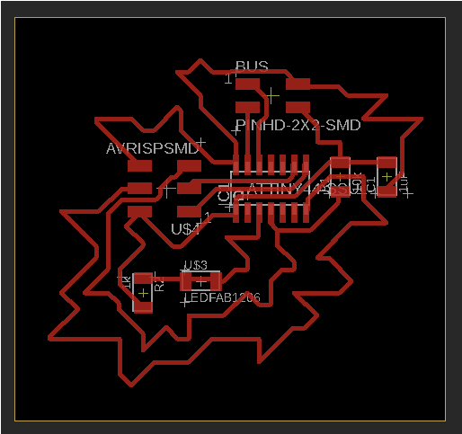
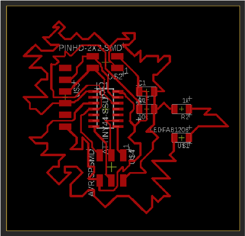
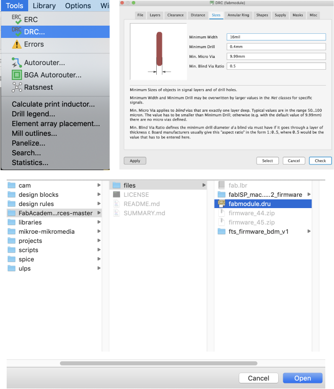
My process for designing the PCB board begins by arranging components corresponding to their connections. To save time I have also tried the “auto-router” tool but it does not allow you to be as creative as I like. Before routing I set the size of the lines to 16mil. Once I am set on a design I am happy with I check the design rules. To do this I navigate to tools->DRC then I select the “load” button on the bottom right of the DRC module and open the fabmodule.dru and then select “check.” Once I get my layout zero errors I prepare it for milling.
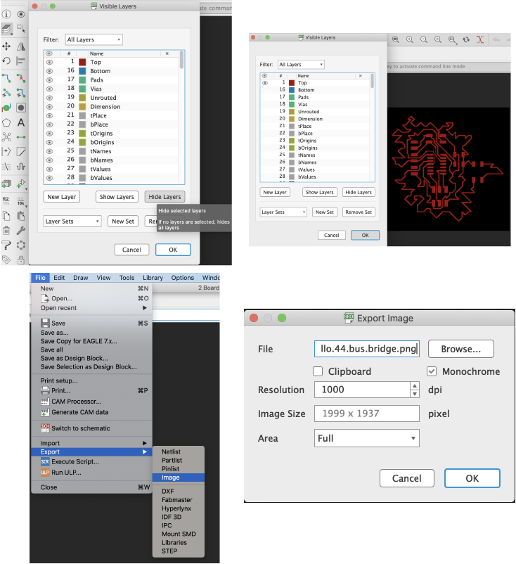
To prepare for milling I need to convert the PCB layout into a PNG file so the Roland monoFab SRM-20 can read my file and mill it. Before I can move into exporting the PNG I have to load my files onto a computer with a Linux operating system. For some weird reason my Mac OS operating system exports PNG files from Rhino 3 times larger than they are supposed to be. After troubleshooting I discovered that using a Linux operating system I can export the PNG to scale.
Now that I am in a proper exporting environment, I open my files in Eagle and load my board file. Next I click on the “layers” tab in the top left corner and select “hide layers,” because I only want the routes (traces) milled and I select to view only the “top” layer. After this i navigate to file->export->image change the “resolution” to 1000 dpi and select the “monochrome” box and save the traces file. I do the exact same steps for exporting the interior, except I select “dimension” layer and hide all others.
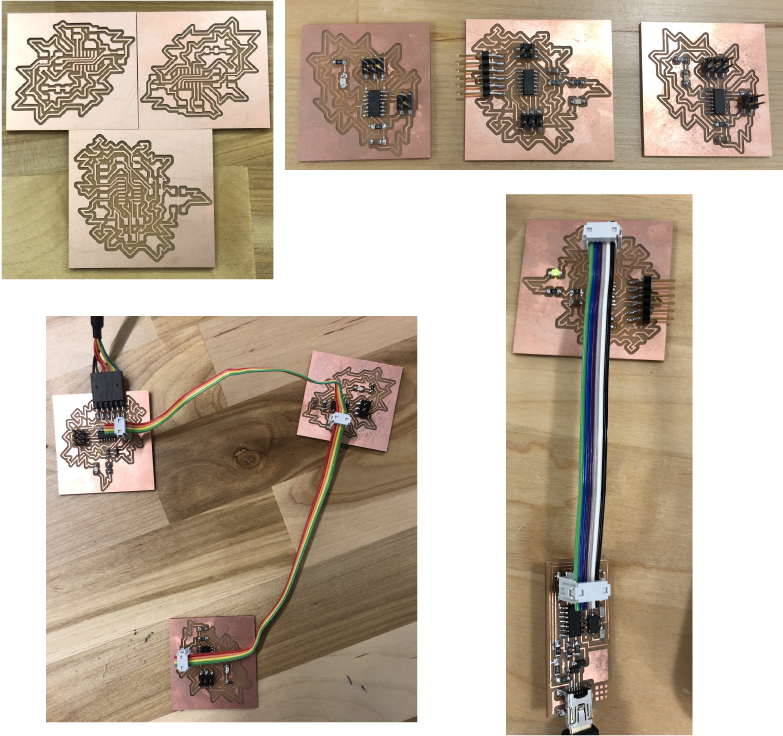
When I went to program the boards I got past burning the boot-loader for the bridge however I connected the nodes wrong and the boards started smoking. After this I decided to take a different route to finish the assignment and go back to troubleshoot this if I have time.
Round 2
Why Use I2C?
To figure out why one might want to communicate over I2C, I first will compare it to the other available options to see how it differs. I already looked a bit into asynchronous but now that I have researched another I will look closer. (I probably should have done this research before choosing to go with asynchronous, but then I never would have learned all of this!(I learn best by doing)).
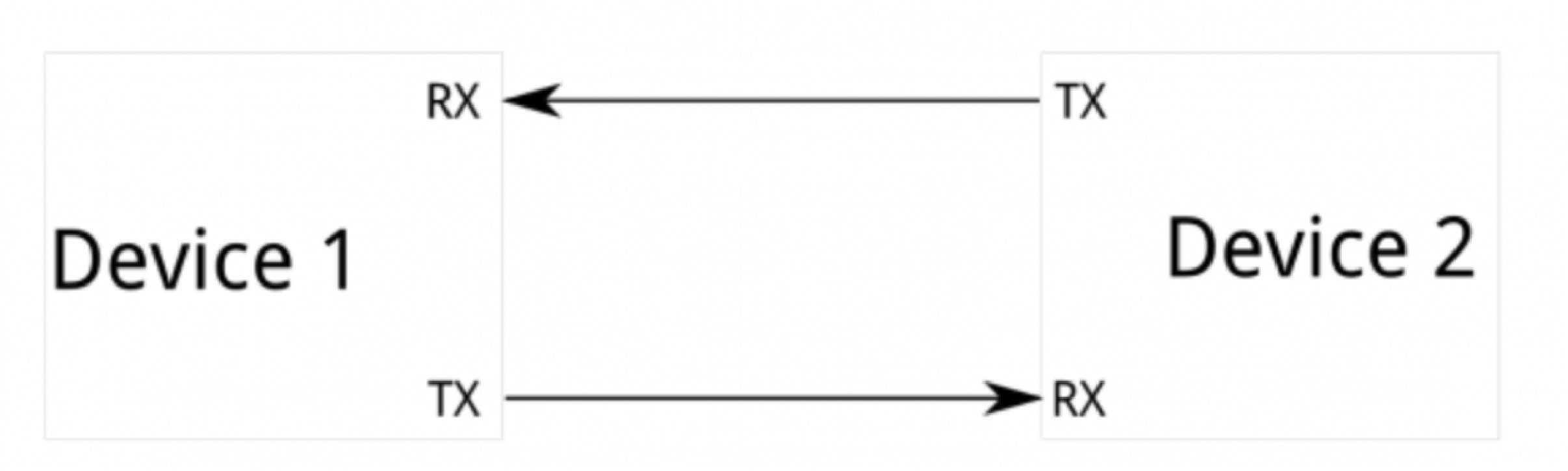
Because serial ports are asynchronous (no clock data is transmitted), devices using them must agree ahead of time on a data rate. The two devices must also have clocks that are close to the same rate. Asynchronous serial ports require hardware overhead–the UART at either end is relatively complex and difficult to accurately implement in software if necessary. UART is not a communication protocol like SPI and I2C, but a physical circuit in a microcontroller, or a stand-alone IC in addition at least one start and stop bit is a part of each frame of data, meaning that 10 bits of transmission time are required for each 8 bits of data sent, which eats into the data rate.
In addition asynchronous serial ports are fundamentally suited to communications between two, and only two, devices. Lastly, while there is no theoretical limit to asynchronous serial communications, most UART devices only support a certain set of fixed baud rates, and the highest of these is usually around 230400 bits per second.
SPI
The most evident drawback of SPI is the number of pins required. Connecting a single master to a single slave with an SPI bus requires four lines; each additional slave requires one additional chip select I/O pin on the master.
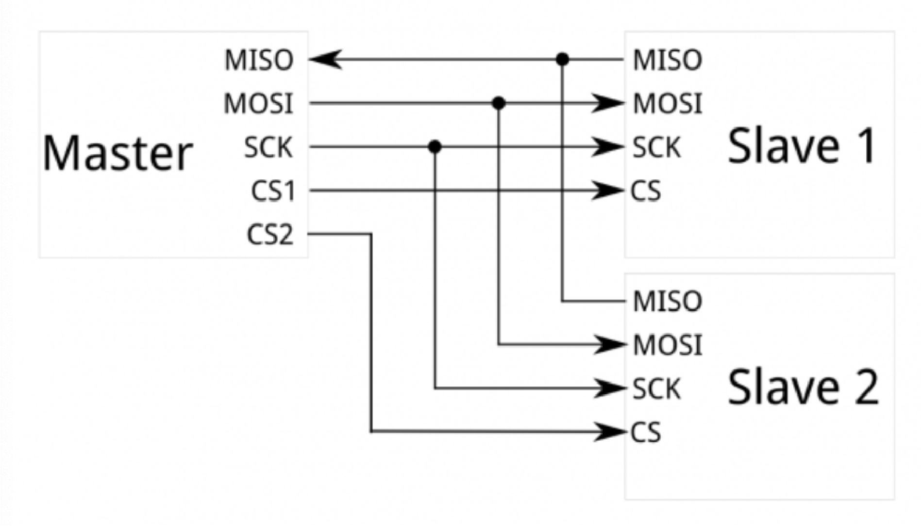
SPI only allows one master on the bus, but it does support an arbitrary number of slaves (subject only to the drive capability of the devices connected to the bus and the number of chip select pins available).
SPI is good for high data rate full-duplex (simultaneous sending and receiving of data) connections, supporting clock rates upwards of 10MHz (10 million bits per second) for some devices, and the speed scales nicely. The hardware at either end is usually a very simple shift register, allowing easy implementation in software.
I2C
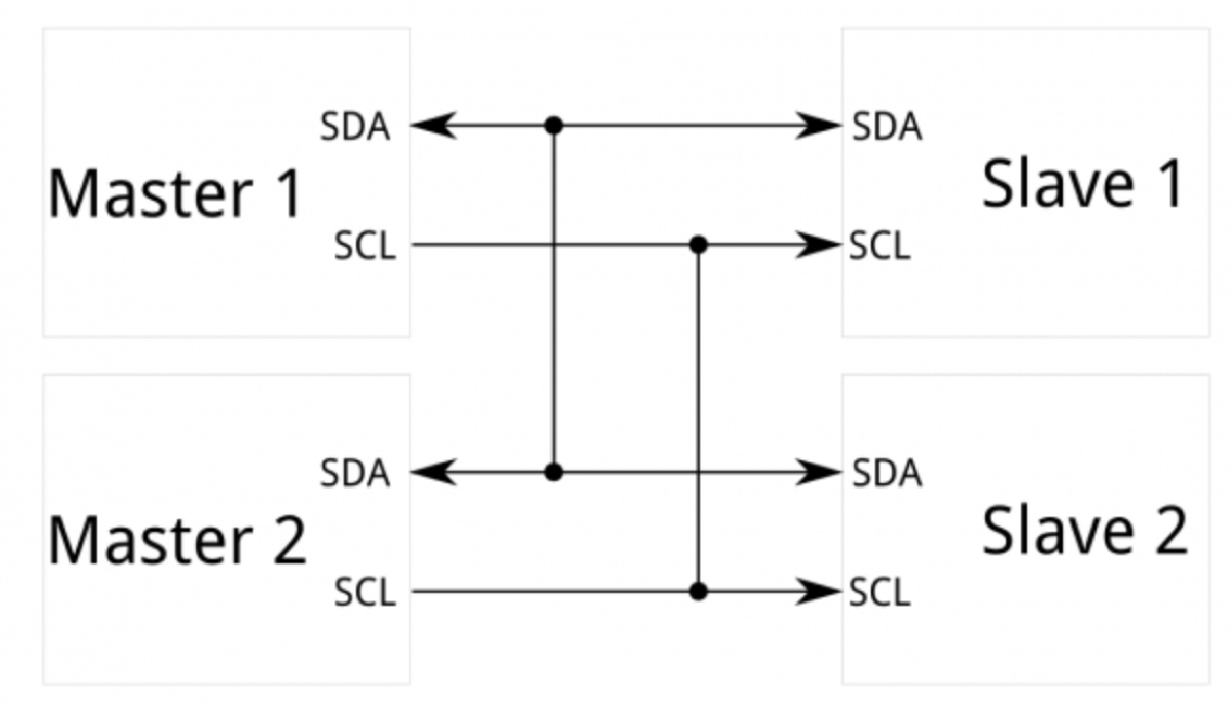
I2C communication The I2C communication is a two wire communication (SCL and SDA). The important thing with it is that we can plug up to 120 different slave devices to those two wires and get datas. What it implies is that we need to get different addresses for each device and set time for each slave device to communicate with the master board. Credit to this fab student for having rock’n documentation!
Furthermore, the Inter-integrated Circuit (I2C) Protocol is a protocol intended to allow multiple “slave” digital integrated circuits (“chips”) to communicate with one or more “master” chips. Like the Serial Peripheral Interface (SPI), it is only intended for short distance communications within a single device. Like Asynchronous Serial Interfaces (such as RS-232 or UARTs), it only requires two signal wires to exchange information but those two wires can support up to 1008 slave devices. unlike SPI, I2C can support a multi-master system, allowing more than one master to communicate with all devices on the bus (although the master devices can’t talk to each other over the bus and must take turns using the bus lines). I2C devices can communicate at 100kHz or 400kHz. There is some overhead with I2C; for every 8 bits of data to be sent, one extra bit of meta data (the “ACK/NACK” bit, which we’ll discuss later) must be transmitted.
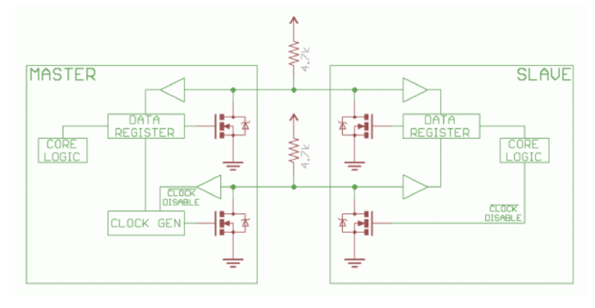
Unlike UART or SPI connections, the I2C bus drivers are “open drain”, meaning that they can pull the corresponding signal line low, but cannot drive it high. Thus, there can be no bus conflict where one device is trying to drive the line high while another tries to pull it low, eliminating the potential for damage to the drivers or excessive power dissipation in the system. Each signal line has a pull-up resistor on it, to restore the signal to high when no device is asserting it low.source
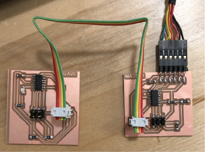
Master
Slave
Libraries
OR
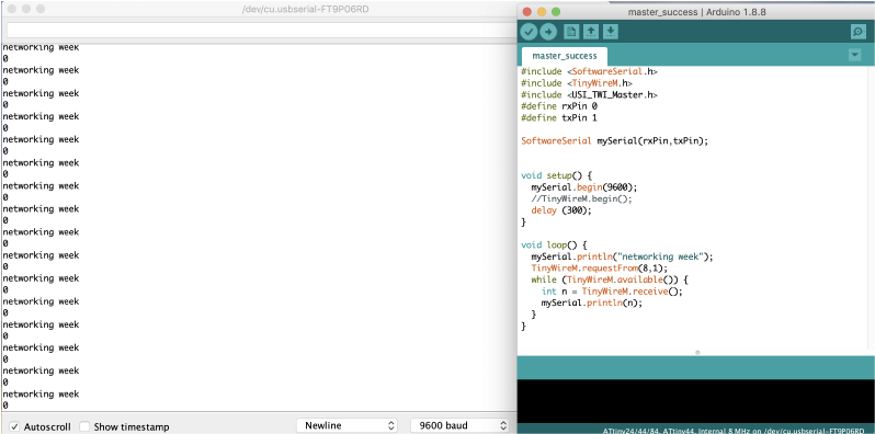
Master Code
#include <SoftwareSerial.h>
#include <TinyWireM.h>
#include <USI_TWI_Master.h>
#define rxPin 0
#define txPin 1

SoftwareSerial mySerial(rxPin,txPin);


void setup() {
  mySerial.begin(9600);
  TinyWireM.begin();
  delay (300);
}

void loop() {
  mySerial.println("networking week");
  TinyWireM.requestFrom(8,1);
  while (TinyWireM.available()) {
    int n = TinyWireM.receive();
    mySerial.println(n);
  }
}
Slave Code
#include <TinyWireS.h> //You need this library to upload the sketch on your slave board

void setup()
{
TinyWireS.begin(8); //I2C communication
TinyWireS.onRequest(test);
}

void loop()
{
TinyWireS_stop_check();
}

void test () //Master calls the slave and the latter one send data
{
TinyWireS.send(0);
}
The master initiates the communication by sending a START bit, this bit alerts all the slaves that some data is coming and they need to listen. After the start bit, 7 bits of a unique slave address is sent. Each slave has it’s own slave address, this way, only one slave will respond to the data. The last sent bit is the read/write bit. If this bit is 0, it means that the master wishes to write data to a register of the slave, if this bit is 1, it means that the master wishes to read data from a register of a slave. Note that all the data is sent MSB (Most Significant Bit) first.
The start bit is generated by pulling the SDA line low, while the SCL is high. And the stop bit is indicated by releasing the SDA to high, along with the SCL being high. So, whenever a module wants to initialize communication, it has to assert SDA line. In our I2C library, which you can find in our compilers, the start bit is sent by calling the “I2C_Start();” function. source
WOOOHOOOOO!!!!!
Data is transferred on the bus in packages of 8 bits. Whenever a device receives a byte, it has to send an acknowledgment bit (ACK bit) back to the master ( this also goes for the first, address, byte). This bit signalizes if the device has received data successfully. Once the sending device is done sending the data through the bus, it will generate a STOP bit, to signalize the end of that conversation, or generate a repeated start, to hold the bus again for some other data transmission.
A module can also initiate what is called a repeated start. The repeated start differs from the start condition in the way that there is no stop condition before it. This way, the slave knows that the incoming bytes are parts of the same message/conversation.
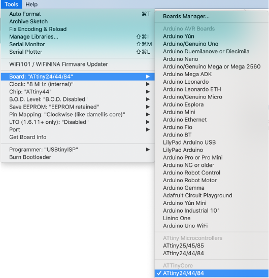
Important: In order to use the wire library in Arduino IDE, my board had to come from ATtiny Core Board manager.
Libraries
Every time the LED blinks my name is printed on the serial monitor:
#include <Wire.h>
#include <SoftwareSerial.h>

#define rxPin 0
#define txPin 1


SoftwareSerial mySerial( rxPin,txPin);
void setup() {
  Wire.begin();        // join i2c bus (address optional for master)
  mySerial.begin(9600);  // start serial for output
}

void loop() {
  Wire.requestFrom(8,6);    // request 6 bytes from slave device #8

  while (Wire.available()) { // slave may send less than requested
    char aleza = Wire.read(); // receive a byte as character
    mySerial.print(aleza);         // print the character
  }

  delay(500);
}
#include <Wire.h>

void setup() {
  Wire.begin(8);                // join i2c bus with address #8
  Wire.onRequest(requestEvent); // register event
  pinMode(7,OUTPUT);
}

void loop() {
  delay(100);
}


void requestEvent() {
  Wire.write("Aleza ");
  digitalWrite(7,HIGH);
  delay(100);
  digitalWrite(7,LOW);
  delay(100);
}