8. Computer controlled machining
CAD -> CAM -> Machining -> Finish & Assembly
This week I tested runout, alignment, speeds, feeds, and toolpaths for our labs machine and made (design+mill+assemble) something big. I began brainstorming, thinking of something I could make big and also use. I have always been interested in furniture design, especially creating new innovative ways to create multifunctional furniture. For instance, when I was 10 yrs old I wanted more floor space in my room so I jimmy rigged my very own Murphy Bed. I am now living on my own for my very first time in a VERY small studio apartment and I decided to design a modular bookshelf, that is portable, modern, and easy to assemble/disassemble. I thought this would be a perfect project to use the skills I learned from the parametric cardboard cutout week.
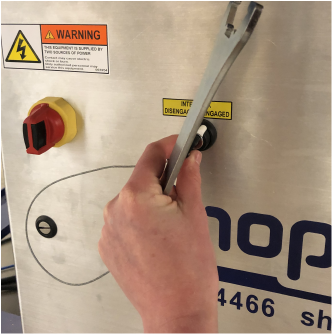
This is my first time ever using a CNC of this scale, and I have to admit I am a little intimidated. This is not only the largest machine in our lab, but also the most dangerous. The first thing my classmates and I did this week was go through a safety seminar.
Machines
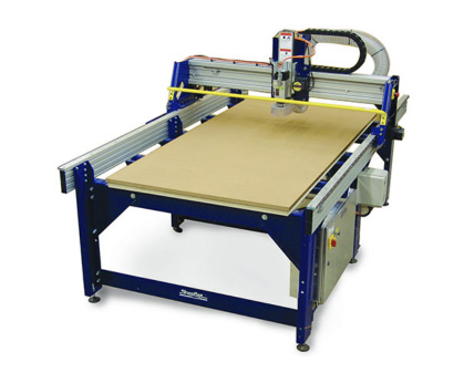
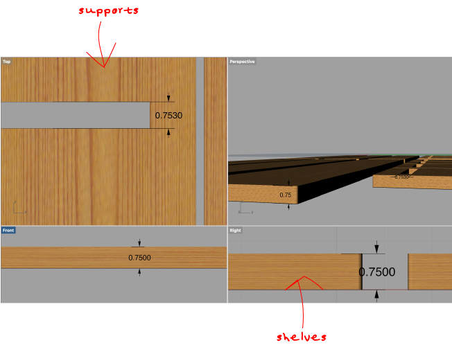
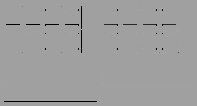
The first step in my process this week was designing a CAD model; I have been trying to use Rhino primary for CADing to get my full use out of the limited free trial. Fusion360 has CAM software built into in that I have heard it is very powerful, and I plan on trying it out sometime in the near future. The design I went with could not have been any simpler. A basic bookshelf needs two things shelves and supports. The sheets of wood in our lab are 0.75 inches thick, with this in mind I placed 2 slots on opposite ends of the supports with widths of 0.753 inches. I left a slight tolerance so the shelves would just fit through the slots. I started the model in 2D (Vectors) and used the extrude tool to transform to 3D (Components). When I was ready to prepare my file to be CAM’d I reverted back to 2D for exporting the file because I really only needed the contours for my project.
3D
2D
CAM
Computer-aided Manufacturing (CAM), is the use of software to control machine tools and related ones in the manufacturing of workpieces. I choose to use VCarve CAM software to prepare my Rhino model for the ShopBot. By preparing I mean creating toolpaths which start calculating the specific movements the CNC machine will follow. Creating these toolpaths is the key stage in going from the virtual world of a computer design to the reality of the physical world.
To begin this process, I first booted VCarve Pro ShopBot Edition 8.5 software on the computer in our lab that is designated to the ShopBot. I then selected create new file from the start-up menu. Next I loaded my model by selecting: File -> Import -> Import Vectors
I was then prompted to enter the Job Setup menu and input the dimensions of my model, which happened to be the size of the the ShopBot table.
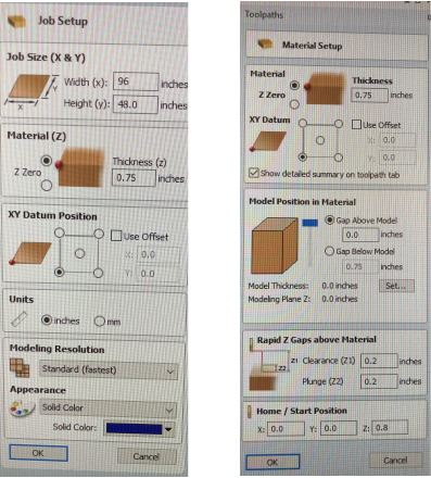
After the job setup I prepared the material setup. This is where I entered the thickness of the material (birch plywood) I would be cutting from. The important variables in this setup fall under the Rapid Z Gaps above Material menu. The clearance (Z1) is the most important setting. This is the height above the job at which it is safe for the cutter to move at rapid or maximum feed rate. The software will raise the bottom of the cutter to this height when it traverses the material. The Plunge (Z2) is an extra feature that can be used to specify a rapid clearance gap for rapid positioning moves above the work piece as well as defining a much smaller gap that the tool will rapid down to during plunge moves. I kept this equal to the Clearance as recommended in the VCarve Support Manual.
Toolpaths
After completing the set-up stages I was ready to enter the toolpath phase. At this point I started to take into account the shape and size of the tool, the type of movement I wanted the tool to make (the shape I want it to leave in the material) and appropriate settings for how fast the tool can be moved and how much material can be removed safely (ALOT OF THINGS).
Pocket Toolpath
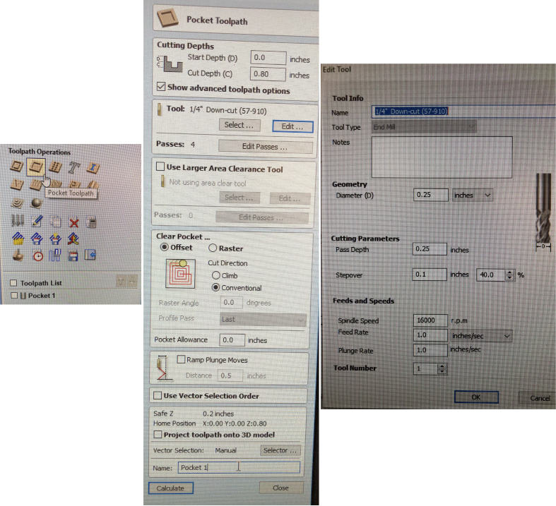
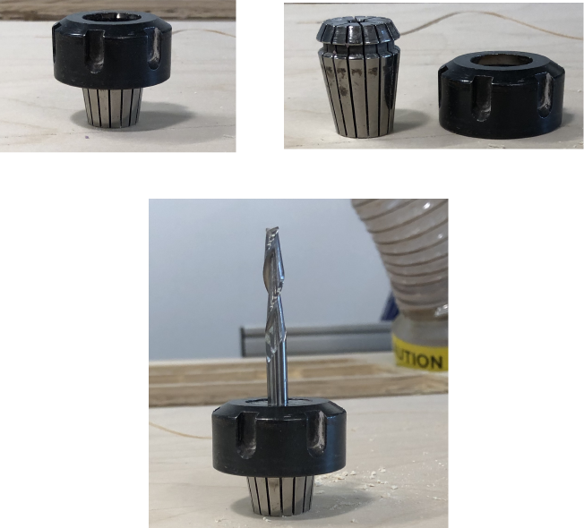
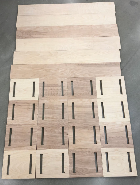
I selected the pocket toolpath for cutting the slots of the supports. I set the Start Depth to 0 because I want to cut directly into the surface of a job. I then set the Cut Depth to 0.8 ; relative to the start depth. Next I selected the Tool I will be using. I went with a 1/4” flute square downcut endmill because I will be primarily making simple cuts in plywood.
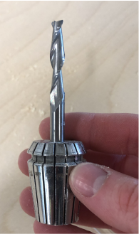
If I were carving 3D contours or carvings I would want to use a ballnose bit, which I demonstrate in the molding and casting week. For very intricate 3D carving I would use a tapered ball nose and if I wanted to do lettering or detailed sign making I would use a V-Bit. I found this documentation to be very helpful in choosing the tool. After I selected the tool I clicked edit to modify the cutting parameters for the selected tool.
As far as specify pass depths VCarve provides a list of current pass depths and the relative spacing of the passes. I went with the suggested value and the program created enough passes until it gets to the Cut Depth set for the toolpath.
To Clear Pocket I selected the Offset fill pattern with a Conventional cutting direction, to clear away the area to be machined wit the Pocket toolpath. This works by calculating an offset area clearance fill pattern to machine inside the selected vector(s). Options for Cut Direction to be either: Climb (CCW) cutting direction Conventional (CW) cutting direction. I was unsure which direction to choose, after doing some reading I settled on the safer option, conventional.
When I Calculated the toolpath I recived this warning message:
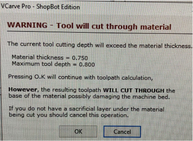
However, I set the tool depth larger than the material thickness to ensure that it cuts all the way through the wood. Our ShopBot table has a “sacrificial layer” to account for variables like this.
Profile Toolpath
I selected the Profile Toolpath cut around and/or along the remaining vectors. The process for specifying this toolpath is the same to that of the pocketing toolpath, however there are a lot more menus and areas of manipulation.
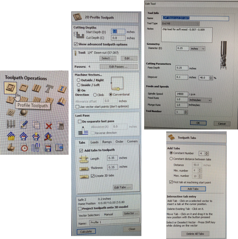
Some areas that differed: Machine Vectors I set to On, which calculated the profile toolpath around the On the selected vectors in a conventional direction.
Tabs I added tabs ensure that there will be no flying parts when cutting them out of material. This was as easy as checking Add tabs option and changing the Constant Number. I changed this to 4 for extra safety.
After the Toolpaths were calculated I utilized a handy gadget Vcarve provides, Preview Toolpaths this allowed me to see how they will look in a virtual piece of material. This helped me check that they are doing what I expected them to. Once I was happy with the Toolpaths I saved them in a format that is appropriate for our particular CNC.
Machining
After I saved my toolpaths I am now need to to adjust the settings and positions on our CNC to match the job setup I specified in the Design/Machining software. This includes: setting the material in the right orientation, and securing it for cutting, loading the correct tool and telling the machine where the X, Y and Z reference position is for the tool tip.
There are two options for securing the material on the CNC bed: VCarve has a Drilling Toolpath that allows one to specify where to place drill holes and translates to the machine, post zeroing. I experienced this process when doing the group assignment. The other way is manually drilling screws into the material and zeroing the machine after (what I did).
Turn the machine on use the control pad to move the Z axis up so you can adjust the endmill. It is important to have the Move/Cut Mode selected to be able to move the machine.
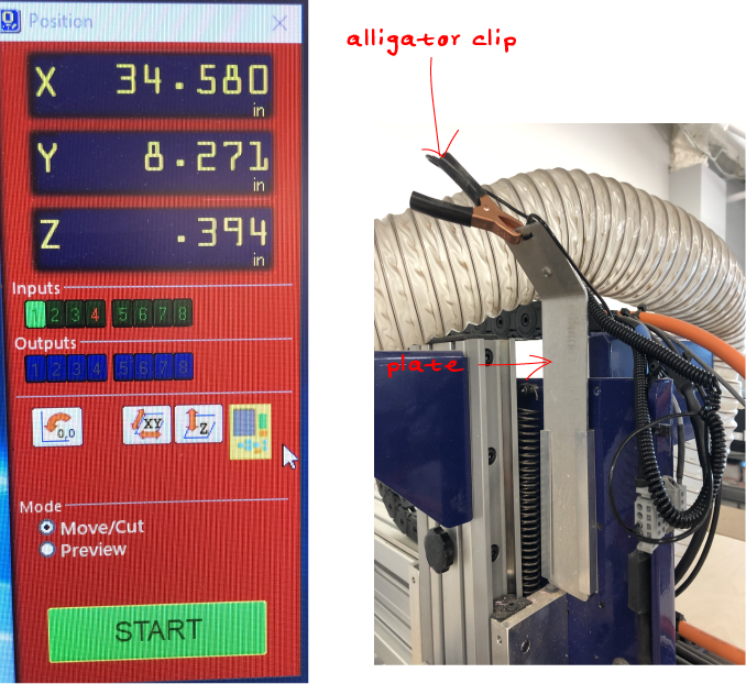
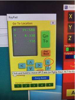
I am now ready to zero the axis. I loaded the ShopBot desktop app and the control menu appeared.
Assembly
Design Files
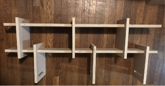
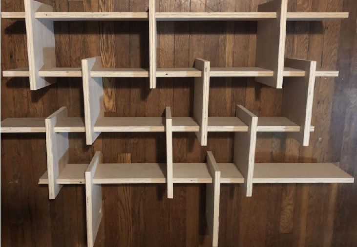
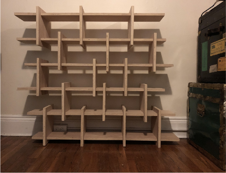
This is my favorite creation from the course thus far. As a designer and artist I aim to create things that make people stop and reflect. I have not been very impressed with any of my projects so far so I doubt anyone else is. My initial ideas are always too ambitious, especially considering I am new to a lot of the topics covered each week (note, this is why I am so drawn to the course, I LOVE TO LEARN). However, I am very pleased with my final product this week, and I think the possibilities are endless. To assemble my object all one needs are the parts, and requires no nails or glue. The tension alone created between the supports and the shelves holds strong.
brush
dogbone