15. Mechanical design
Rube Gershenfeld Machine
This week I worked alongside my group to design a machine that includes mechanism+actuation+automation, built the mechanical parts and operated it manually. We decided to make a Rube Goldberg Machine. This may be my favorite assignment thus far because of the creativity and collaboration it constitutes. We appointed our classmate Daniel Smithwick to be our delegate and you can find the detailed story of our project on his page.
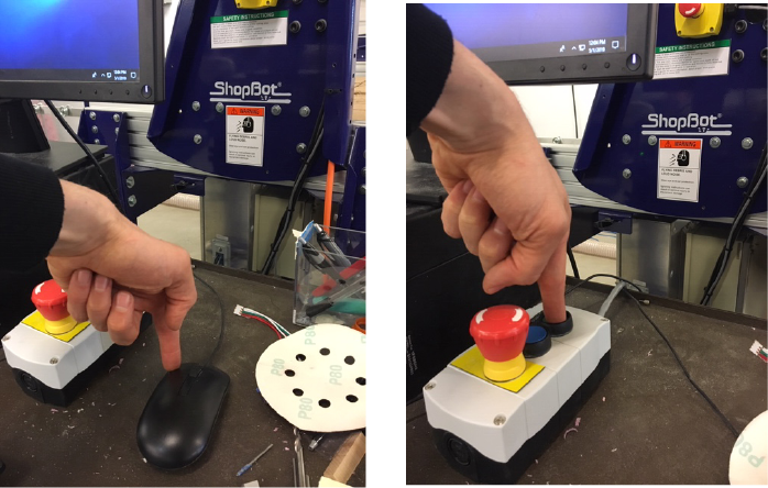
To be a true Rube Goldberg Machine the system has to work free from human intervention, the ONLY exception to that rule is at the start of the machine. Our Rube Goldberg machine’s task will be to press the two buttons needed to start the ShopBotin our lab (the left mouse button and the pendant button). the Shopbot will then cut out a piece of plywood which…in theory could be used to assemble a new r.g. machine, or even assemble itself, and thus we may very well tear a hole in the fabric of the spacetime continuum as we know it.
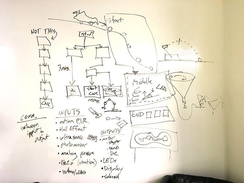
To get the ball rolling we assigned ourselves homework, to each sketch out our own modules or subsystems that we wanted to incorporate in the final machine (must include an input and/or an output) Below is my sketch.
End Tasks - Press button (we all suffer from buttonphobia, the fear of pressing buttons, so this machine will come in handy).
My modules goal is to either trigger the beginning of the entire machine or press the final button. Either way I will be creating some type of subsystem that uses force to trigger a reaction. Rube Goldberg machines usually have some sort of animal that plays a part in triggering a series of reaction. So I thought it would clever to have a robot animal (no live animals were harmed in this production).
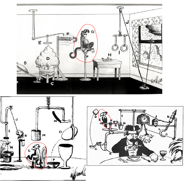
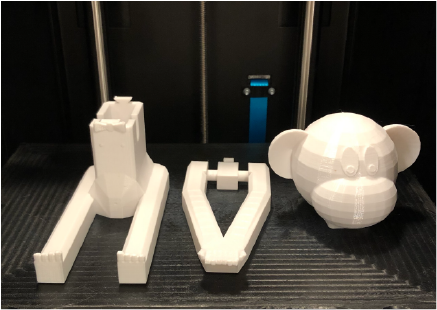
I followed this tutorial to create the first prototype of my subsystem that I have named: Code Monkey
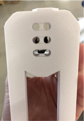
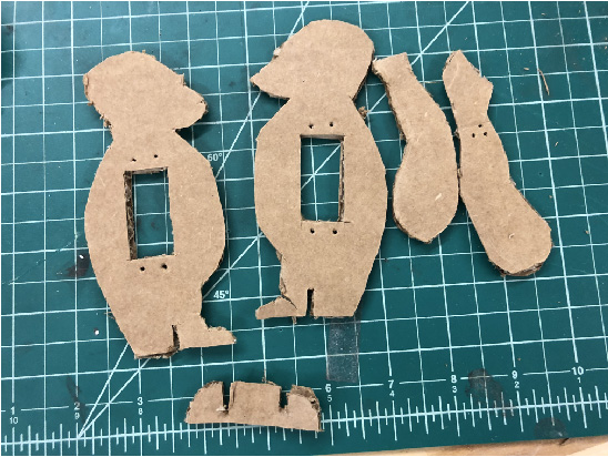
First I cut a simple cardboard profile for the body. This would have been done more efficiently and neatly using a laser cutter but both our machines were out of service in our lab, so I hand cut using a box cutter.
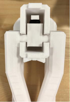
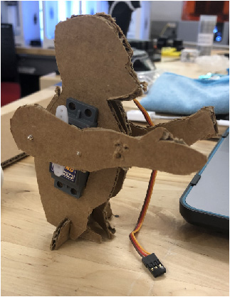
The photo above shows the constructed monkey with a servo motor installed.
I used an Arduino and breadboard for the purpose of a quick prototype, however I will be designing and producing my own board for the final product. This is only my second time every playing around with an Arduino; I am more familiar with designing PCB in Eagle, milling, and soldering my own boards. I am not exactly sure how to correctly connect the wires, however there is huge community built around Arduino so there are a lot of places to look for trouble shooting.
Connections
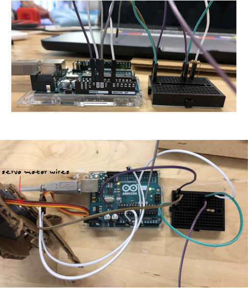
- red servo wire -> brown wire -> pin i1 on bread board
- orange servo wire -> white wire -> pin 9 on Ardunio
- brown servo wire -> white wire -> connected to GND pin on Ardunio
- purple wire : pin J1 on bread board -> 5v pin on Ardunio
- green wire: pin F1 pin on bread board-> pin J10 on bread board
- white wire: pin J13 on bread boardd -> A0 on Ardunio
- 10k resistor: pins F10 & F13 on bread board
- “switch wires” : purple G10 on bread-board, grey GND on Ardunio
Arduino Sketch
#include <Servo.h>

Servo myservo;  // create servo object to control a servo

const int triggerCable = 2;     // the cinnection port (digital in this case) for the trigger cable

int triggerState = 0;         // variable for reading the status of the trigger cables (connected or not)

int armUp = 90;       //rotation degree of the servo when the arm is up
int armMid = 45;      //standard position for when the arm is moving
int armDown = 0;      //rotation degree of the servo when the arm is down
int armPause = 800;   //the time we allow the servo to rech the instructed position


void setup() {
  Serial.begin(9600);
  pinMode(triggerCable, INPUT);   // initialize the trigger cable pin as an input:
  myservo.attach(9);              // attaches the servo on pin 9 to the servo object
}

void loop(){
  // read the state of the trigger cable value:
  triggerState = digitalRead(triggerCable);
  Serial.println(triggerState);

  // check if the pushbutton is pressed.
  // if it is, the triggerState is HIGH:
  if (triggerState == HIGH) {
    // turn LED on:
    myservo.write(armDown);   // tell servo to go to armDown position
    delay(armPause);        // tells the program to wait as longs as specified in "armPause", gives the servo time to reach the defined position

    myservo.write(armUp);   // tell servo to go to armUp position
    delay(armPause);        // tells the program to wait as longs as specified in "armPause", gives the servo time to reach the defined position
  }
  else {
    // turn LED off:
    myservo.write(armMid);   // tell servo to go to armMid position
  }
}
This code is supposed to program the monkey to move its servo connected arm with I connect the two “switch” wires together. This worked however the arm also moved randomly with no switch. Thus, there are either issues in my code and/or connections. This is my first time working with a servo motor though so I am pretty excited to see a result.
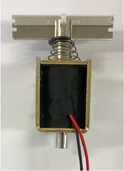
Monkapult
The servo arm powered monkey was a good first round prototyping exorcize however my subsystems task in the machine changed. The new function is to launch a ball that reaches the next subsystem that triggers a reaction to the next. I was loking at different catapult mechanisms for this. I still wanted to run with the monkey idea, so why not a “Monkapult.” This mechanism essentially works as a spring loaded hinge. The monkeys arms are on a hinge loaded by rubber bands.