11. Input devices
In order to successfully master input and output I need to look deeper into programming. I communicated with the serial monitor in week 11 however I did not exactly output accurate readings. So i decided to play around with an Arduino UNO for some fast prototyping studies. Arduino has a very powerful community surrounding its organization. Arduino IDE has many libraries that allow you to communicate with compatible boards that one can mill and design themselves.
ARDUINO TEMPERATURE SENSOR (THERMISTOR)
To begin thermistors are simple, inexpensive, and accurate components that make it easy to get temperature data for your projects. Remote weather stations, home automation systems, and equipment control and protection circuits are some applications where thermistors would be ideal. The are analog sensors, so the code is relatively simple compared to digital temperature sensors that require special libraries and lots of code.
HOW A THERMISTOR WORKS
Thermistors are variable resistors that change their resistance with temperature. They are classified by the way their resistance responds to temperature changes. In Negative Temperature Coefficient (NTC) thermistors, resistance decreases with an increase in temperature. In Positive Temperature Coefficient (PTC) thermistors, resistance increases with an increase in temperature.
NTC thermistors are the most common, and that’s the type we’ll be using in this tutorial. NTC thermistors are made from a semiconducting material (such as a metal oxide or ceramic) that’s been heated and compressed to form a temperature sensitive conducting material.
The conducting material contains charge carriers that allow current to flow through it. High temperatures cause the semiconducting material to release more charge carriers. In NTC thermistors made from ferric oxide, electrons are the charge carriers. In nickel oxide NTC thermistors, the charge carriers are electron holes.
A BASIC THERMISTOR CIRCUIT
Since the thermistor is a variable resistor, we’ll need to measure the resistance before we can calculate the temperature. However, the Arduino can’t measure resistance directly, it can only measure voltage.
The Arduino will measure the voltage at a point between the thermistor and a known resistor. This is known as a voltage divider. The equation for a voltage divider is:
V(out) = V(in) * (R2/R1+R2)
V(out): Voltage between thermistor and known resistor V(in): VCC i.e. 5V R1: Known resistor value R2: Resistance of thermistor
This equation can be rearranged and simplified to solve for R2, the resistance of the thermistor:
R2= R1 * (V(in)/V(out)-1)
Finally, the Steinhart-Hart equation is used to convert the resistance of the thermistor to a temperature reading.
CONNECT THE CIRCUIT
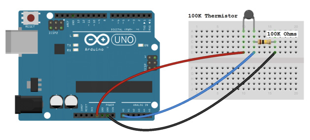
The value of the resistor should be roughly equal to the resistance of your thermistor. In this case, the resistance of my thermistor is 100K Ohms, so my resistor is also 100K Ohms.
CODE FOR SERIAL MONITOR OUTPUT OF TEMPERATURE READINGS
int ThermistorPin = 0;
int Vo;
float R1 = 10000;
float logR2, R2, T;
float c1 = 1.009249522e-03, c2 = 2.378405444e-04, c3 = 2.019202697e-07;

void setup() {
Serial.begin(9600);
}

void loop () {

  Vo = analogRead(ThermistorPin);
  R2 = R1 * (1023.0 / (float)Vo - 1.0);
  logR2 = log(R2);
  T = (1.0 / (c1 + c2*logR2 + c3*logR2*logR2*logR2));
  T = T - 273.15;
  T = (T * 9.0)/ 5.0 + 32.0;
  Serial.print("Temperature: ");
  Serial.println(T);
  Serial.println(" F");

  delay(500);
}
Serial Monitor Result:
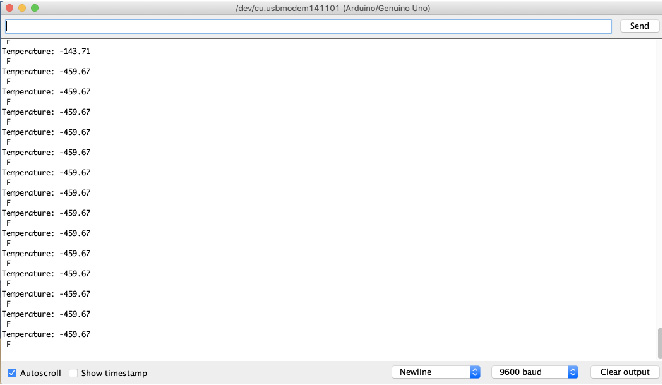
Yes, my temperature reading might is off given that it translates to absolute zero, but it works!!!
This program will display Celsius and Fahrenheit at the same time:
int ThermistorPin = 0;
int Vo;
float R1 = 10000;
float logR2, R2, T, Tc,Tf
float c1 = 1.009249522e-03, c2 = 2.378405444e-04, c3 = 2.019202697e-07;

void setup() {
Serial.begin(9600);
}

void loop () {

  Vo = analogRead(ThermistorPin);
  R2 = R1 * (1023.0 / (float)Vo - 1.0);
  logR2 = log(R2);
  T = (1.0 / (c1 + c2*logR2 + c3*logR2*logR2*logR2));
  Tc = T - 273.15;
  Tf = (Tc * 9.0)/ 5.0 + 32.0;


  Serial.print("Temperature: ");
  Serial.print(Tf);
  Serial.print(" F; ");
  Serial.print(Tc);
   Serial.println(" C");

  delay(500);
}
I would like to take this further and connect an LCD output of the temperature readings. circuit basics
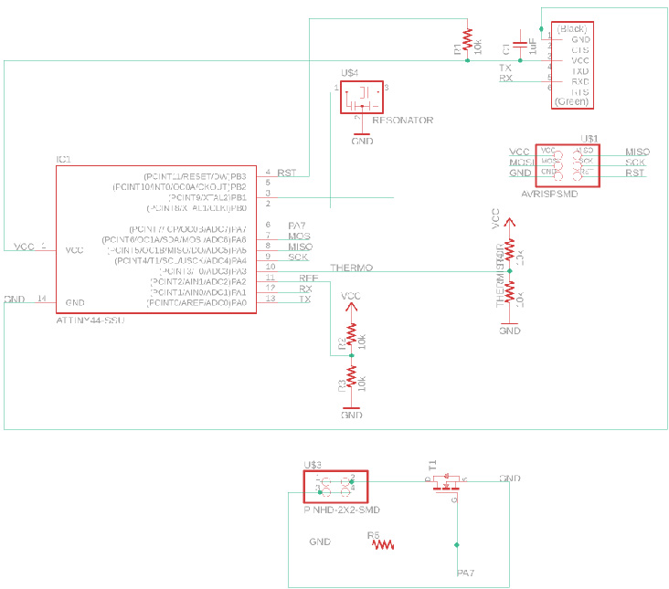
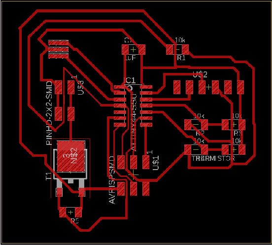
This week I added a thermistor sensor to a microcontroller board that I designed and read it. For this weeks assignment I was inspired by the project of a FabAcademy 2018 graduate, Oye. Being a newbie to electronics this proved to be very hard. In the spirit of spiral development I ended up making a simple board with a Thermistor.
Components
- 20 MHz RESONATOR (1)
- ATTINY44-SSU (1)
- AVRISPSMD (1)
- FTDI-SMD-HEADER (1)
- 10k RESISTOR (5)
- 10k Thermistor (1)
- 1uF CAP-UNPOLARIZED (1)
- MOSFET- TO252 (1)
- PINHD-2X2-SMD (1)
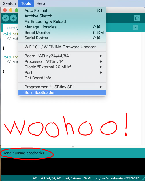
Once I finished soldering my board I connected it to my fabISP that was connected to my computer. I opened Arduino and proceeded to “burn bootloader” tool, to check if my boards connections were working between each other… I recieved this error message:
 Arduino: 1.8.8 (Mac OS X), Board: "ATtiny24/44/84, ATtiny44, External 20 MHz"

avrdude: Yikes!  Invalid device signature.
         Double check connections and try again, or use -F to override
         this check.

Error while burning bootloader.

This report would have more information with
"Show verbose output during compilation"
option enabled in File -> Preferences.
So I went back to the “drawing board” <- haha
Trouble-shooting
First I tested if my fabISP (programmer) had something to do with the error. With my fabISP still connected to my computers USB port, I connected one of my instructors (Greg Buckland) personal boards and tried to burn bootloader again. This time it worked! While I still had Gregs board handy I wanted to try one more check. I uploaded the code Greg wrote for his board into Arduino and my ISP successfully programmed his board. So my programmer board is not the issue.
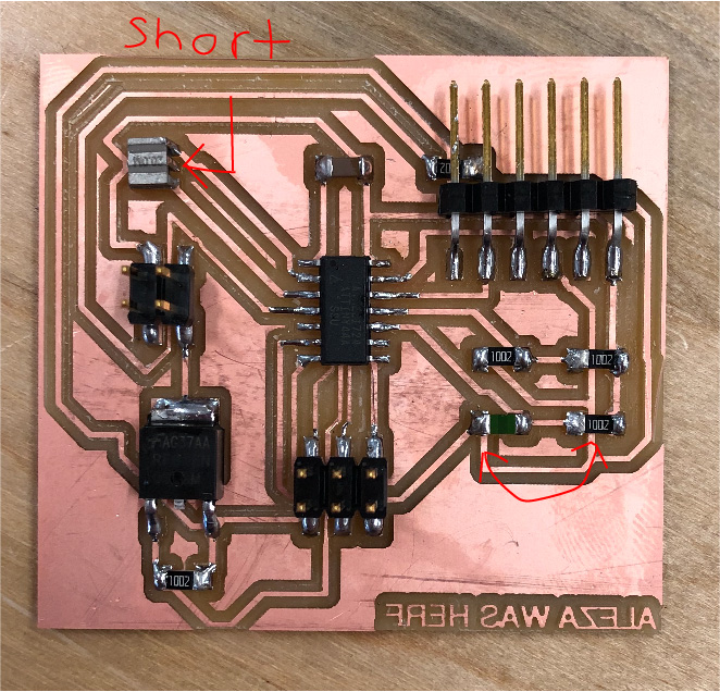
Second I checked back with my schematic and compared it to my soldered board. I noticed that my thermistor and resistor were in each-others spot and needed to be swapped (this shouldn’t have affected the connections).
Third I reviewed continuity using a multimeter. I started by checking the ATtiny44 (microcontroller) GND (ground) and VCC (voltage), which were good. Then tested the connections between the AVRISP-SMD HEADER (all connections checked out),then moved to the FTDI (all connections checked out). Next up, the resonator… I discovered that there was a short circuit! I returned to the soldering station and removed the resonator with a heat gun, removed excess solder, and replaced the component.
BOARD POST SURGERY
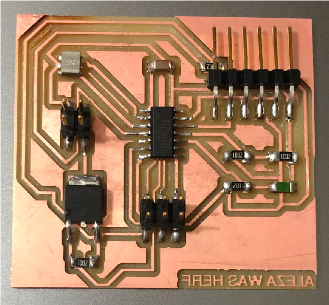
DUN DUH DUN....
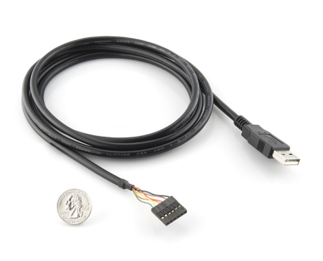
Serial Communication
Future Technology Devices International
FTDI refers to software drivers for converting RS-232 or TTL serial transmissions to USB signals, in order to allow support for legacy devices with modern computers.
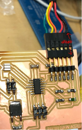
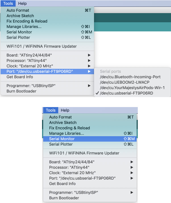
Now I want to test the serial communication through the FTDI.
//Counts button presses and sends the count over serial connx
//The following lines of code modified from:
//https://www.hackster.io/porrey/easy-serial-on-the-attiny-2676e6
#include <SoftwareSerial.h>
// ***
// *** Define the RX and TX pins. Choose any two
// *** pins that are unused. Try to avoid D0 (pin 5)
// *** and D2 (pin 7) if you plan to use I2C.
// ***
#define TX 1 // PA0, pin 12
#define RX 0 // PA1, pin 13
// ***
// *** Define the software based serial port. Using the
// *** name Serial so that code can be used on other
// *** platforms that support hardware based serial. On
// *** chips that support the hardware serial, just
// *** comment this line.
// ***
SoftwareSerial Serial(RX, TX);
//end quoted code
int counter = 0;
void setup() {
// put your setup code here, to run once:
Serial.begin(9600);
Serial.println("Starting serial communication...");
Serial.print("Counter: "); Serial.println(counter);
delay(200);
}
void loop() {
// put your main code here, to run repeatedly:
delay(1000);
counter++;
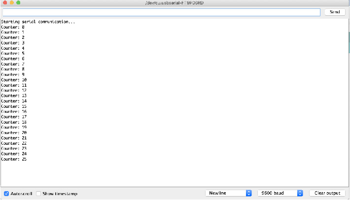
Serial.print("Counter: "); Serial.print(counter); Serial.println("");
}
SUCCESS
Now I wanted to test code for my thermistor:
// thermistor-1.ino Simple test program for a thermistor for Adafruit Learning System
// https://learn.adafruit.com/thermistor/using-a-thermistor by Limor Fried, Adafruit Industries
// MIT License - please keep attribution and consider buying parts from Adafruit
//The following lines of code modified from:
//https://www.hackster.io/porrey/easy-serial-on-the-attiny-2676e6
// as quoted in http://archive.fabacademy.org/2018/labs/fablabdassault/students/greg-buckland/exercise12.html

#include <SoftwareSerial.h>
// ***
// *** Define the RX and TX pins. Choose any two
// *** pins that are unused. Try to avoid D0 (pin 5)
// *** and D2 (pin 7) if you plan to use I2C.
// ***

#define TX    1  // PA0, pin 12, white cable
#define RX    0  // PA1, pin 13, green cable

// ***
// *** Define the software based serial port. Using the
// *** name Serial so that code can be used on other
// *** platforms that support hardware based serial. On
// *** chips that support the hardware serial, just
// *** comment this line.
// ***
SoftwareSerial Serial(RX, TX);

// the value of the 'other' resistor
#define SERIESRESISTOR 10000

// What pin to connect the sensor to
#define THERMISTORPIN 3

void setup(void) {
  Serial.begin(9600);
}

void loop(void) {
  float reading;

  reading = analogRead(THERMISTORPIN);

  Serial.print("Analog reading ");
  Serial.println(reading);

  // convert the value to resistance
  reading = (1023 / reading)  - 1;     // (1023/ADC - 1)
  reading = SERIESRESISTOR / reading;  // 10K / (1023/ADC - 1)
  Serial.print("Thermistor resistance ");
  Serial.println(reading);

  delay(1000);
}
UNSUCCESSFUL