Assignment
group assignment:
test the design rules for your 3D printer(s)
individual assignment:
-design and 3D print an object (small, few cm3, limited by printer time)
that could not be made subtractively
- 3D scan an object (and optionally print it)
Introduction
What is 3D Printing?
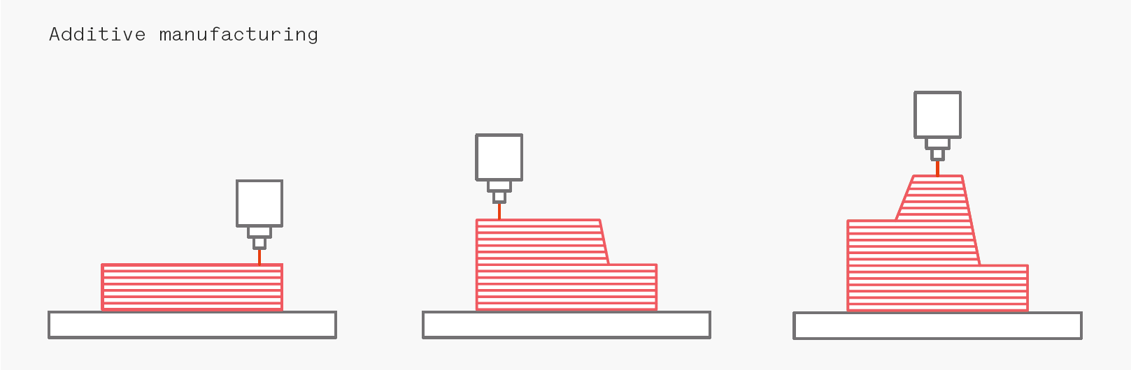
3D printing or additive manufacturing is a process of making three-dimensional solid objects from a digital file. The creation of a 3D printed object is achieved using additive processes. In an additive process an object is created by laying down successive layers of material until the object is created. Each of these layers can be seen as a thinly sliced horizontal cross-section of the eventual object. 3D printing is the opposite of subtractive manufacturing which is cutting out / hollowing out a piece of metal or plastic with for instance a milling machine. 3D printing enables you to produce complex (functional) shapes using less material than traditional manufacturing methods.(Source :- https://www.3dprinting.com)
The Process
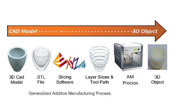
Step 1 is to create a 3D model on CAD software.Step 2 is to export the model to STL format which is the most common 3D Printing file format, that stands for STereoLithography.
Step 3 is to use a slicing software that translates the 3D File into instructions for the 3D printer to follow.
Step 4 is to generate the g-code.
Step 5 is printing.
Step 6 is taking the 3D object from the machine and removing the unneeded parts.
Type of 3D printers
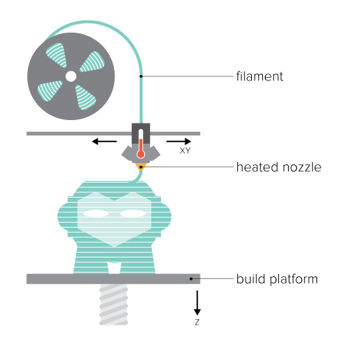
FDM
FDM (Fused Deposition Modeling) Is the 3D Printing technology most people are familiar with
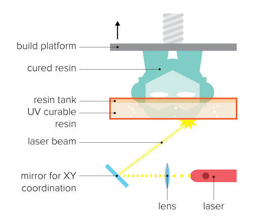
SLA & DLP
SLA (Stereolithography) and DLP (Direct Light Processing are similar technologies. They both use a photopolymer resin that is solidified by a certain wavelength of UV light.
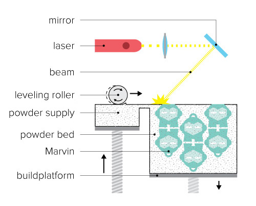
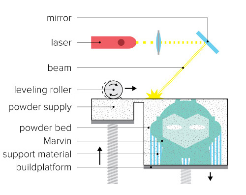
Selective Laser Sintering (SLS)
Selective Laser Sintering (SLS) uses a laser to melt and solidify layers of powdered material into finished objects.
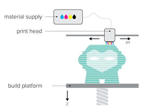
Material Jetting (PolyJet and MultiJet Modeling)
Material Jetting (Stratasys PolyJet and 3D Systems MultiJet Modeling) technologies are similar to inkjet printing, but instead of jetting drops of ink onto paper, these 3D printers jet layers of liquid photopolymer onto a build tray and cure them instantly using UV light.
Metal Printing (Selective Laser Melting and Electron Beam Melting)
SLM and EBM are used in industrial 3D printing. Materials include various metals and alloys including steel, titanium, aluminum, cobalt-chrome and nickel.
(Source :- https://www.og3dprinting.com)
test the design rules for your 3D printer(s)
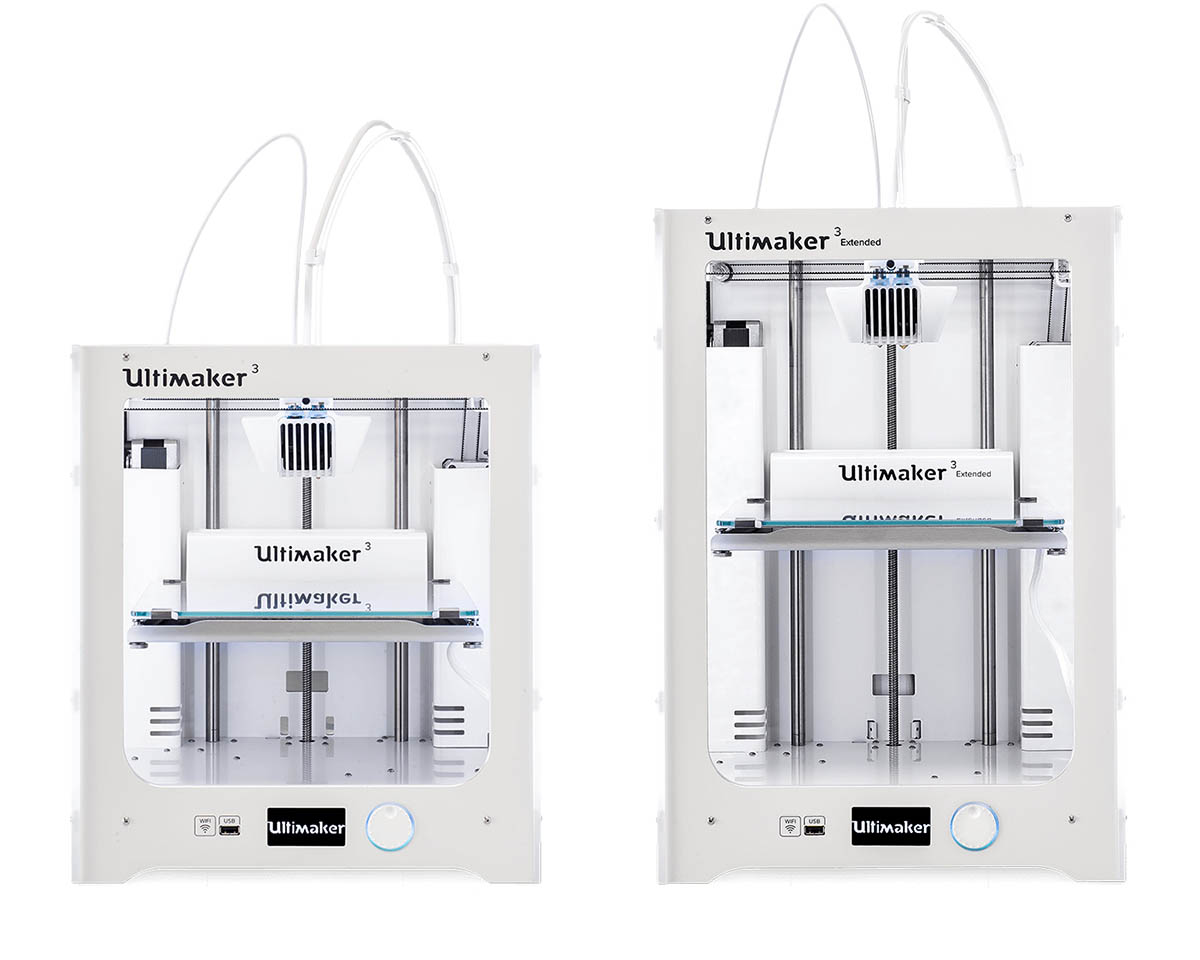
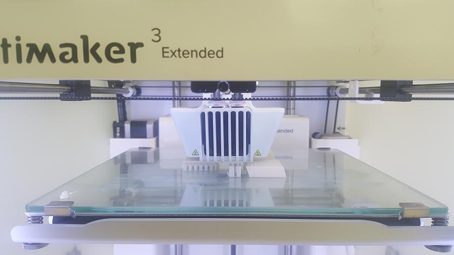
Ultimaker 3 (Extended)
Precision/Orverhang test
A Precision/Orverhang test was performed on a Ultimaker3 3D printer and Cura slicer.
The Precision/Orverhang test was downloaded from thingiverse. It just took 40 min to print and gave very decent result.
The settings used are the preset standard settings for a normal quality print with PLA filament:
- Layer height: 0.15mm
- Wall thickness: 1mm
- Infill Density: 20%
- Print temperature: 200degC
- Build plate: 60 degC
- Print speed> 80mm/s
- Printing temperature:200degC
- Support: Non
- Build pate adhesion type> none
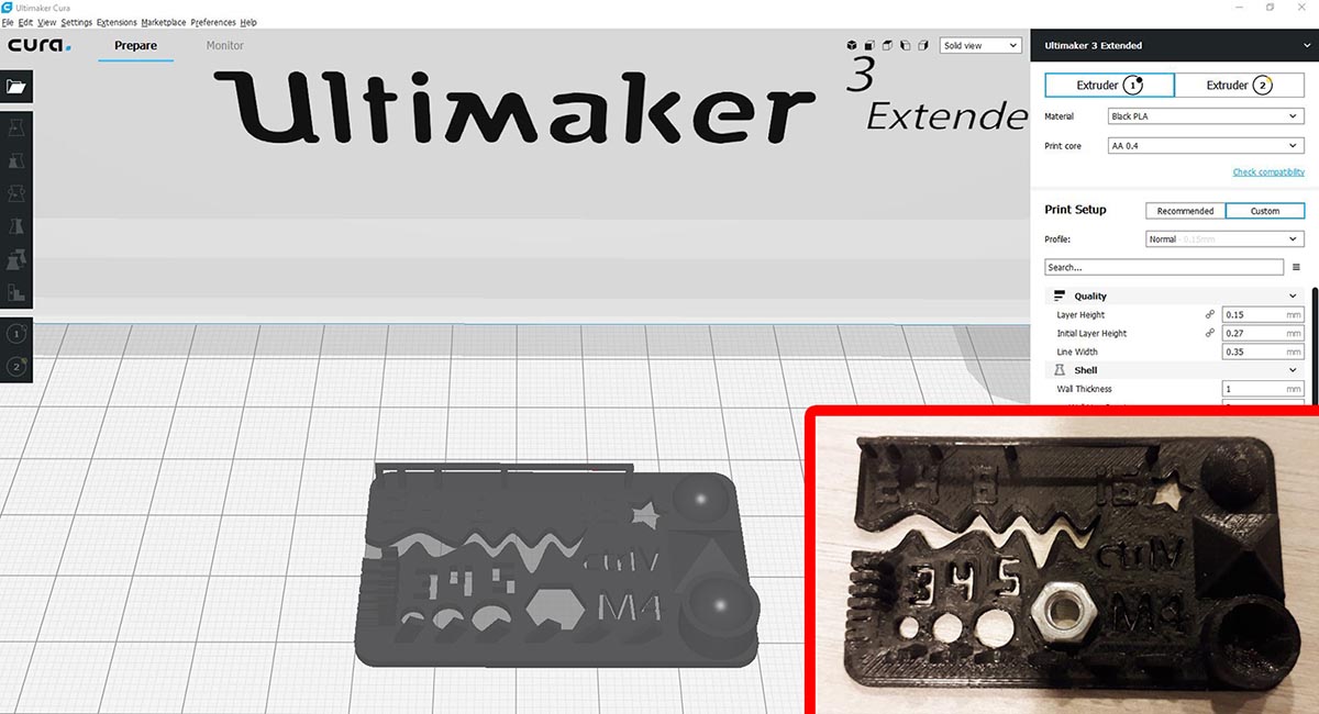
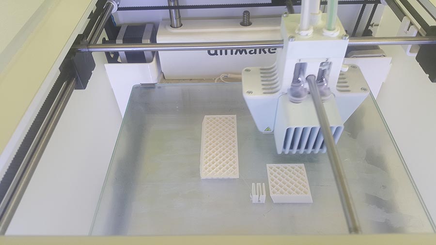
Results:
- Hole size (3 holes 3/4/5mm):Good precision
- Nut size (M4 Nut should fit perfectly): It takes a hard push to fit
- Fine details (pyramide, cone, all numbers): Good
- Rounded print (wave, half sphere): Good
- Minimum distance and walls (0.1/0.2/0.3/0.4/0.5/0.6/0.7mm): Only 0.7 and 0.6 are fully separated
- Overhang (25°/30°/35°/40°/45°): Pass
- Bridge print (2/4/8/16/mm): Pass
- Surface (all the flat parts): Good
Tolerance/Precision test
A Tolerance/Precision test was performed on the Ultimaker3 Extended 3D printer and Cura slicer.
The Tolerance/Precision test was downloaded from thingiverse.The test features moving hinges of varying tolerances ranging from 0.38mm up to 0.635mm. It also features thin walls and wells ranging down to 0.016mm
The settings used are the same used for the previous test with PLA filament.
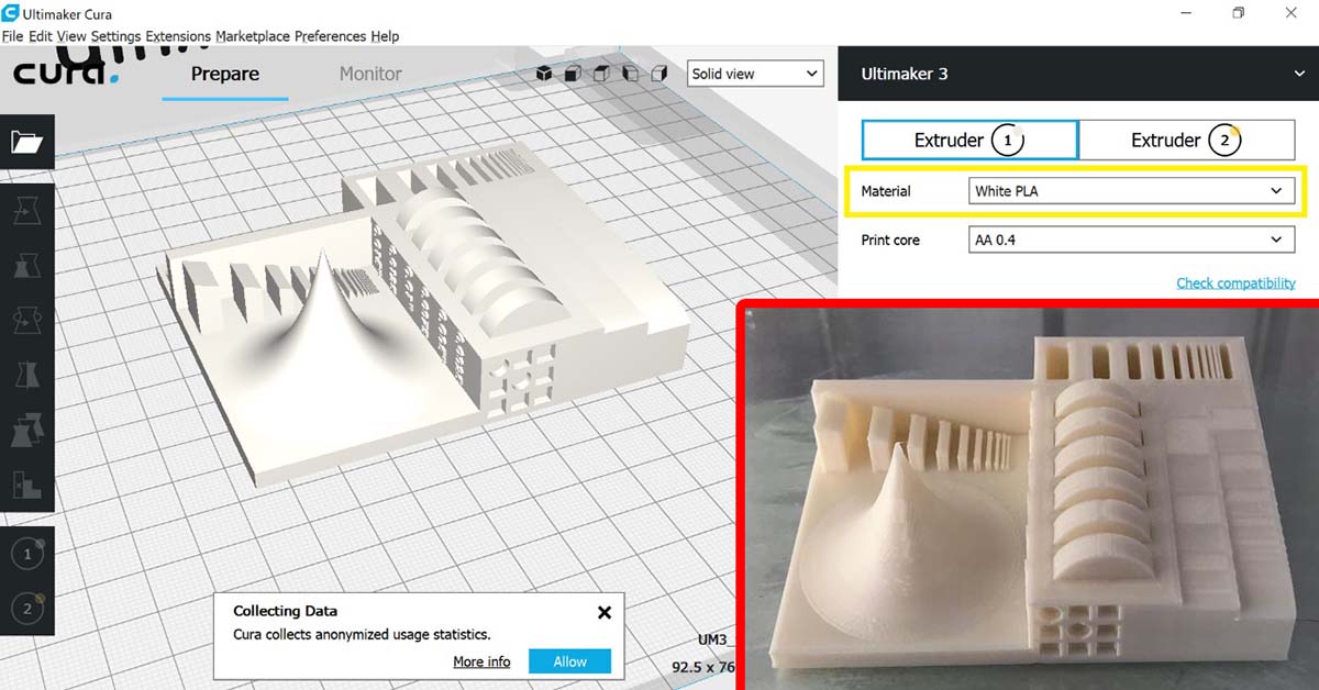
Results:
- Thin walls and wells: Clean
- Range of curvature: Good
- Sloping surfaces to test z-axis resolution: Good
- Sharp peak: Very Sharp
- Cavity: Clean
- Moving hinges of varying tolerances: All were stuck
design and 3D print an object (small, few cm3, limited by printer time) that could not be made subtractively
Designing
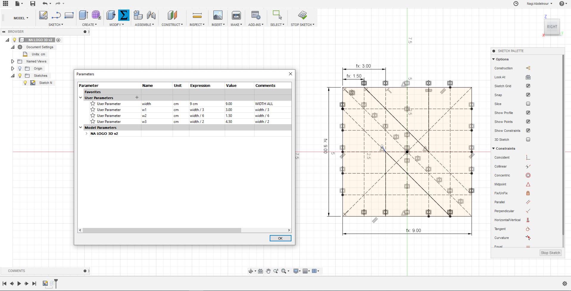
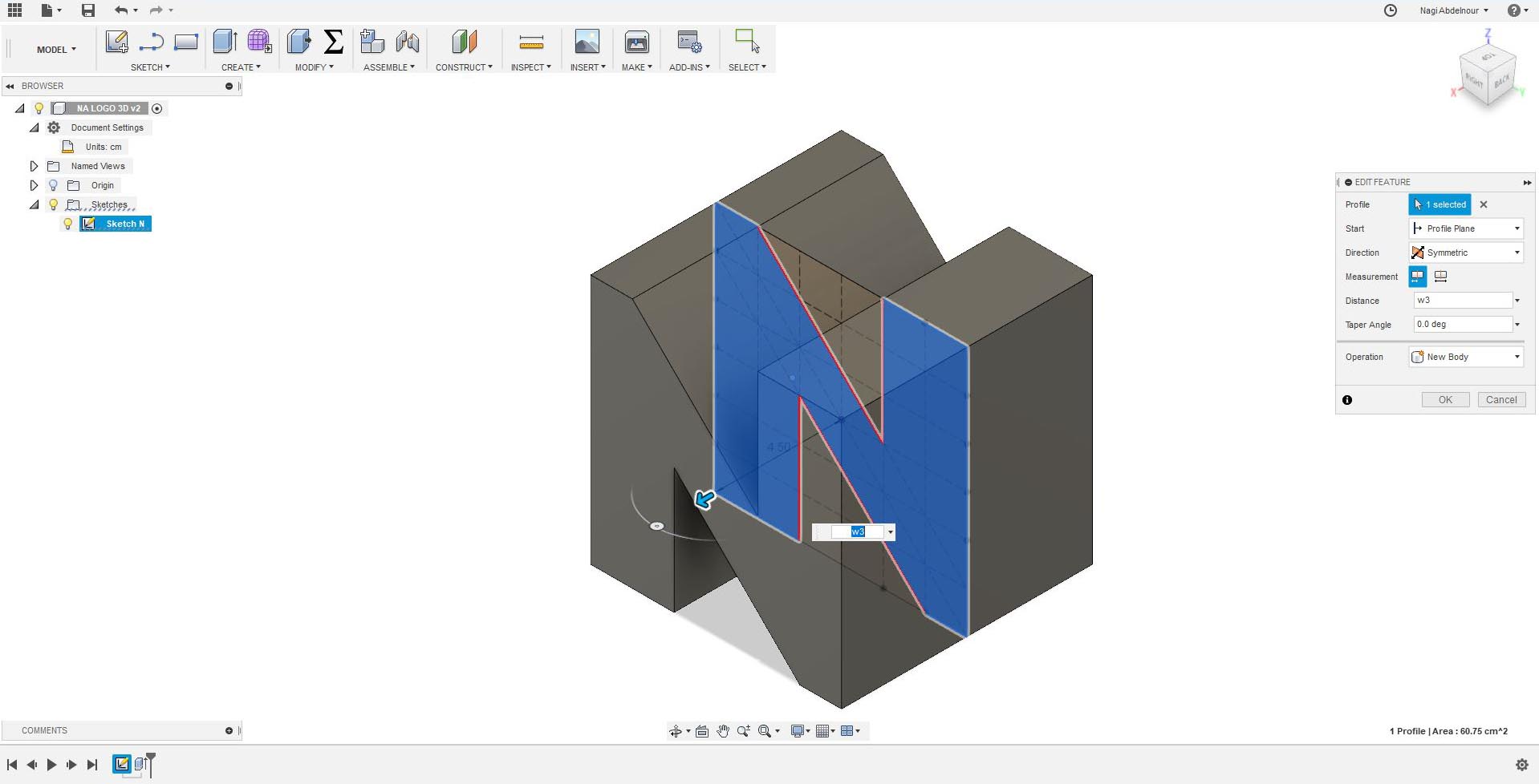
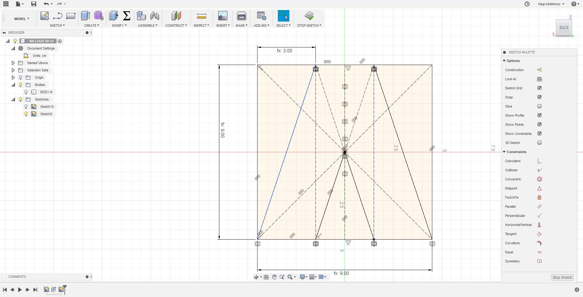
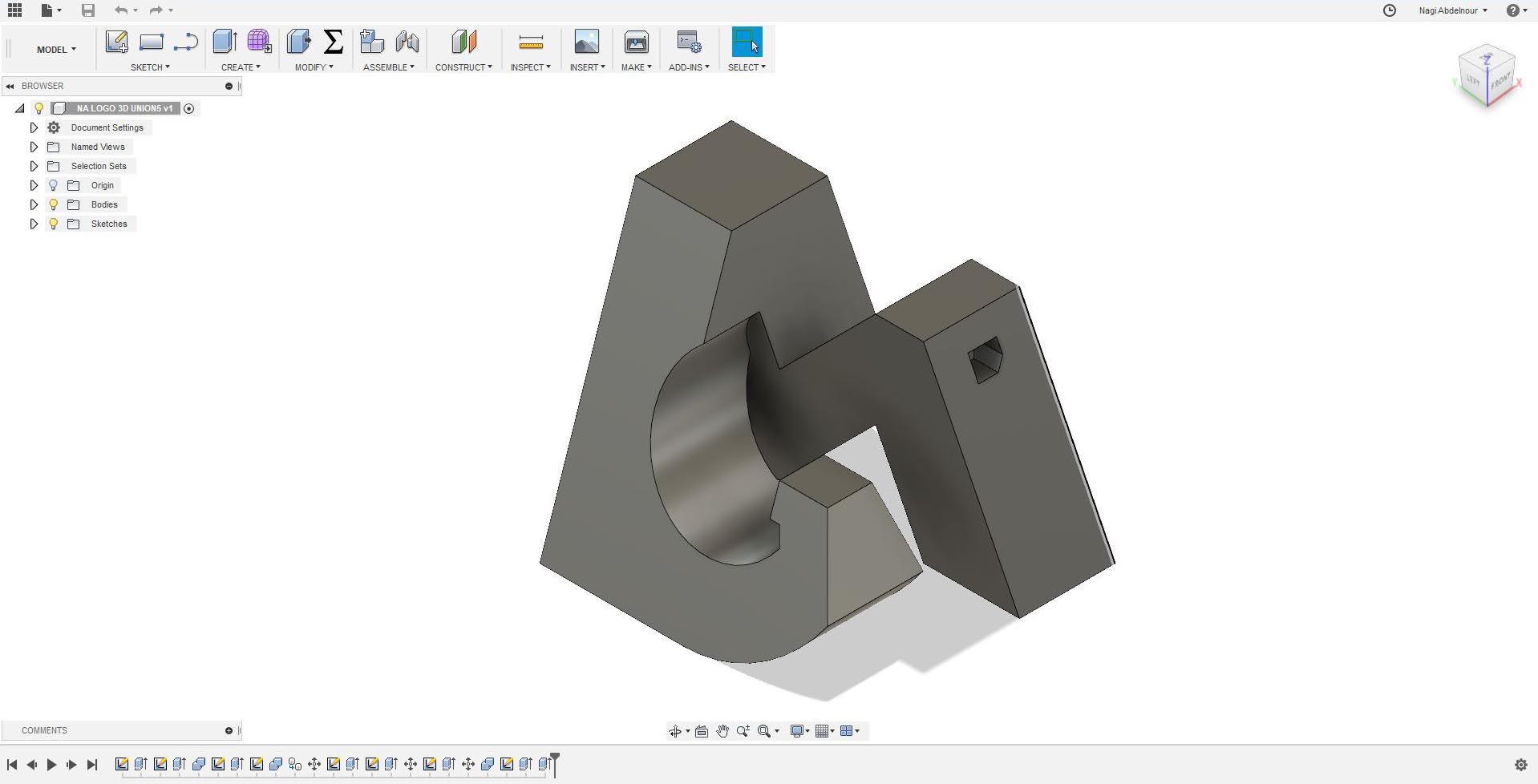
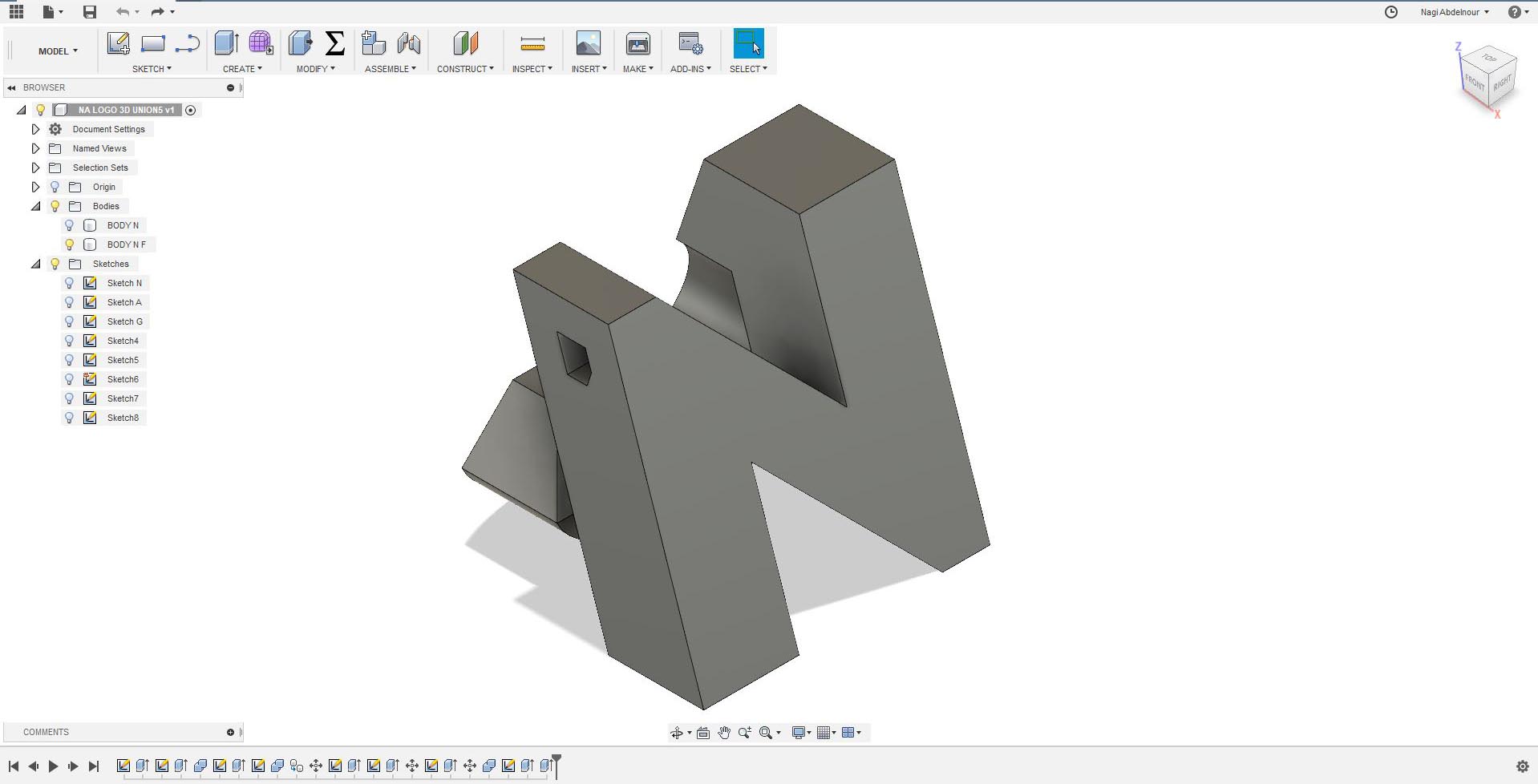
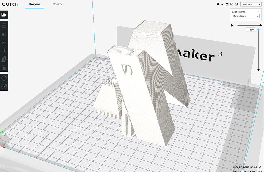
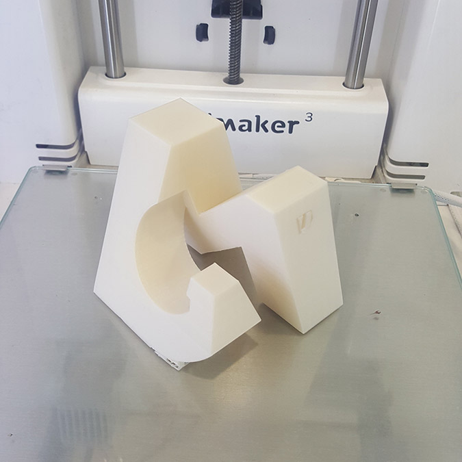
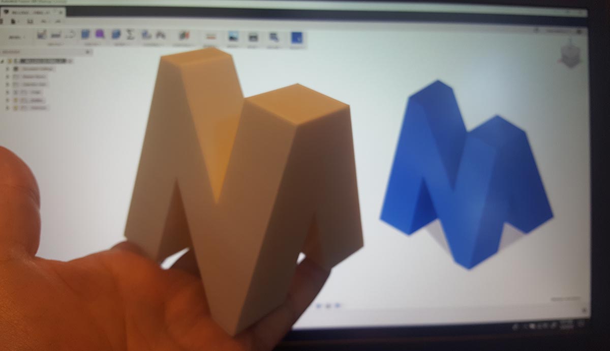
For This assignments I decided to model my logo in 3D where I will have my name's letter on each face of a cube...N A G I...
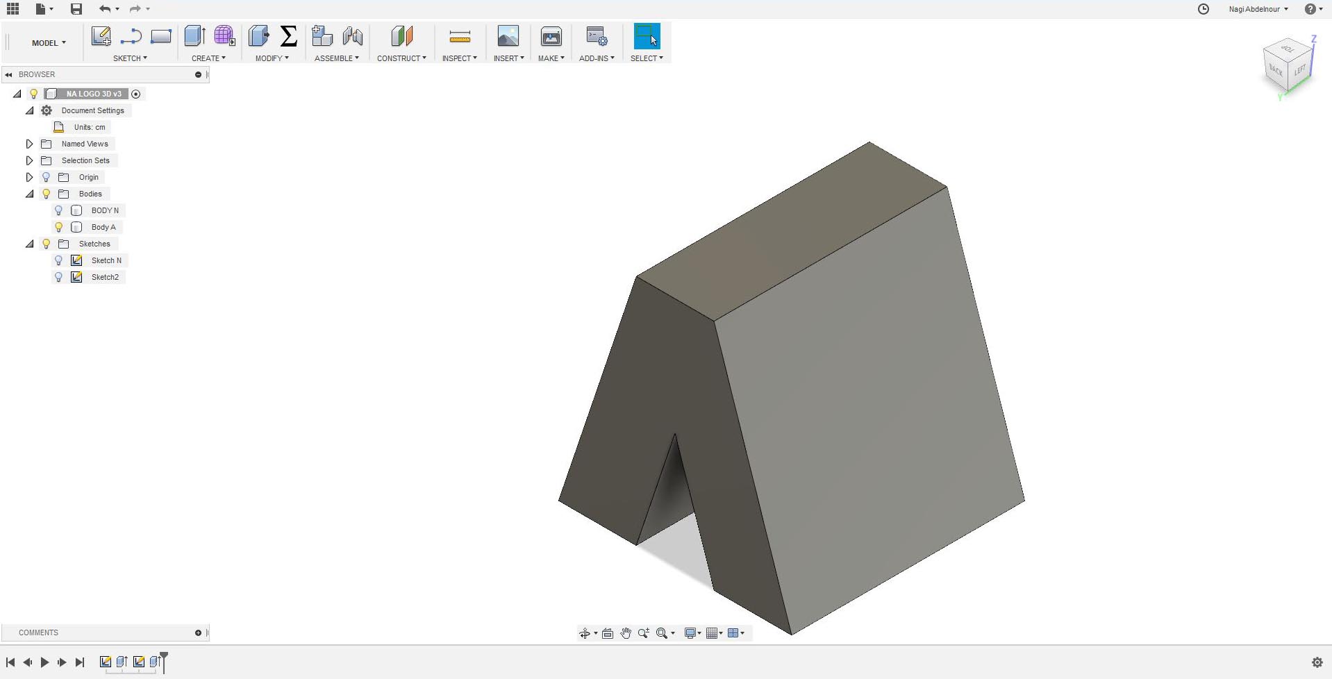
For that I will use Fusion software and start by adding some parameters and sketch than press pull the letter N on the first face of a cube.
Then will continue with the second face and sketch than press pull the letter A.
Now I will use the combine command and intersect the letter N and the letter A.Then sketch the letter G on the third face.
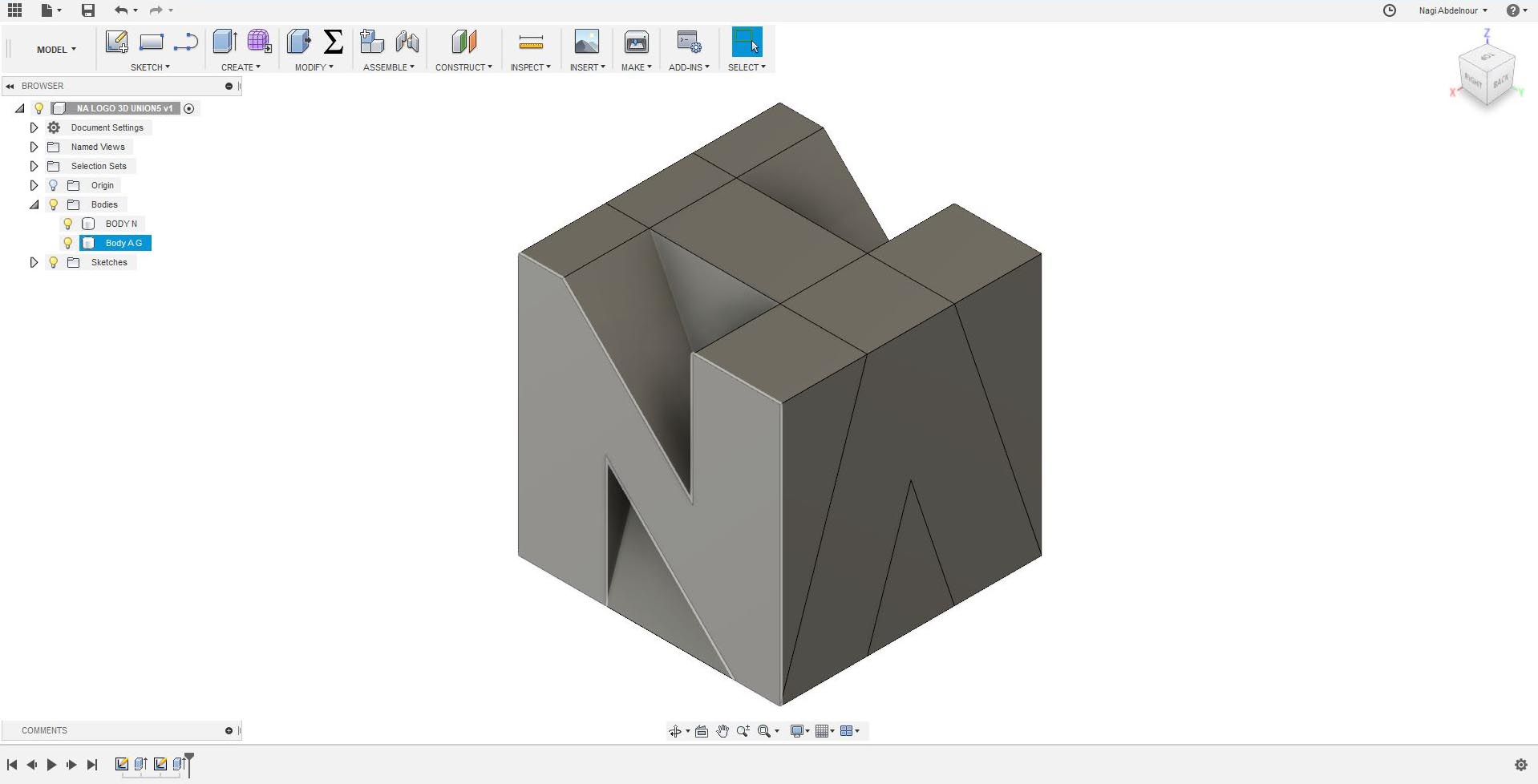
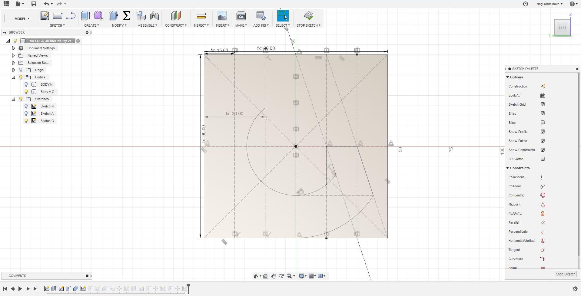
Then press pull the letter G and intersect it with the left part of the letter A.Than combine/union the result with the letter N.
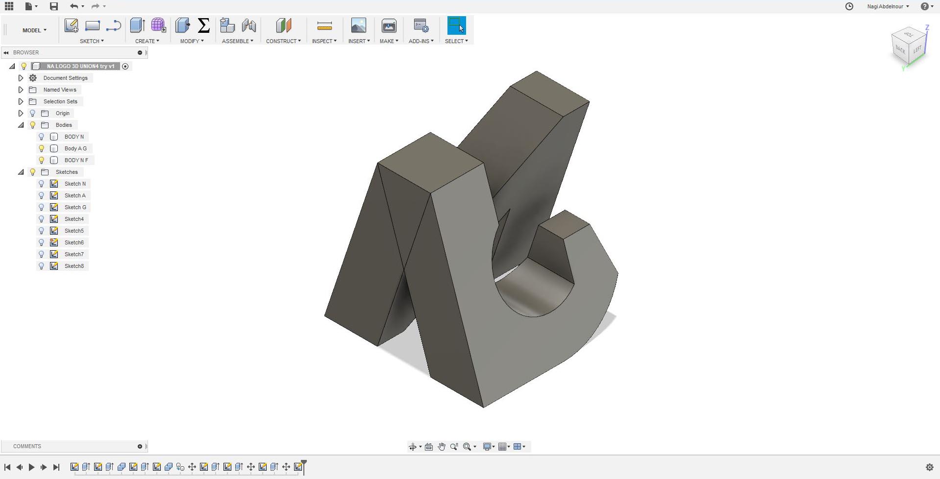
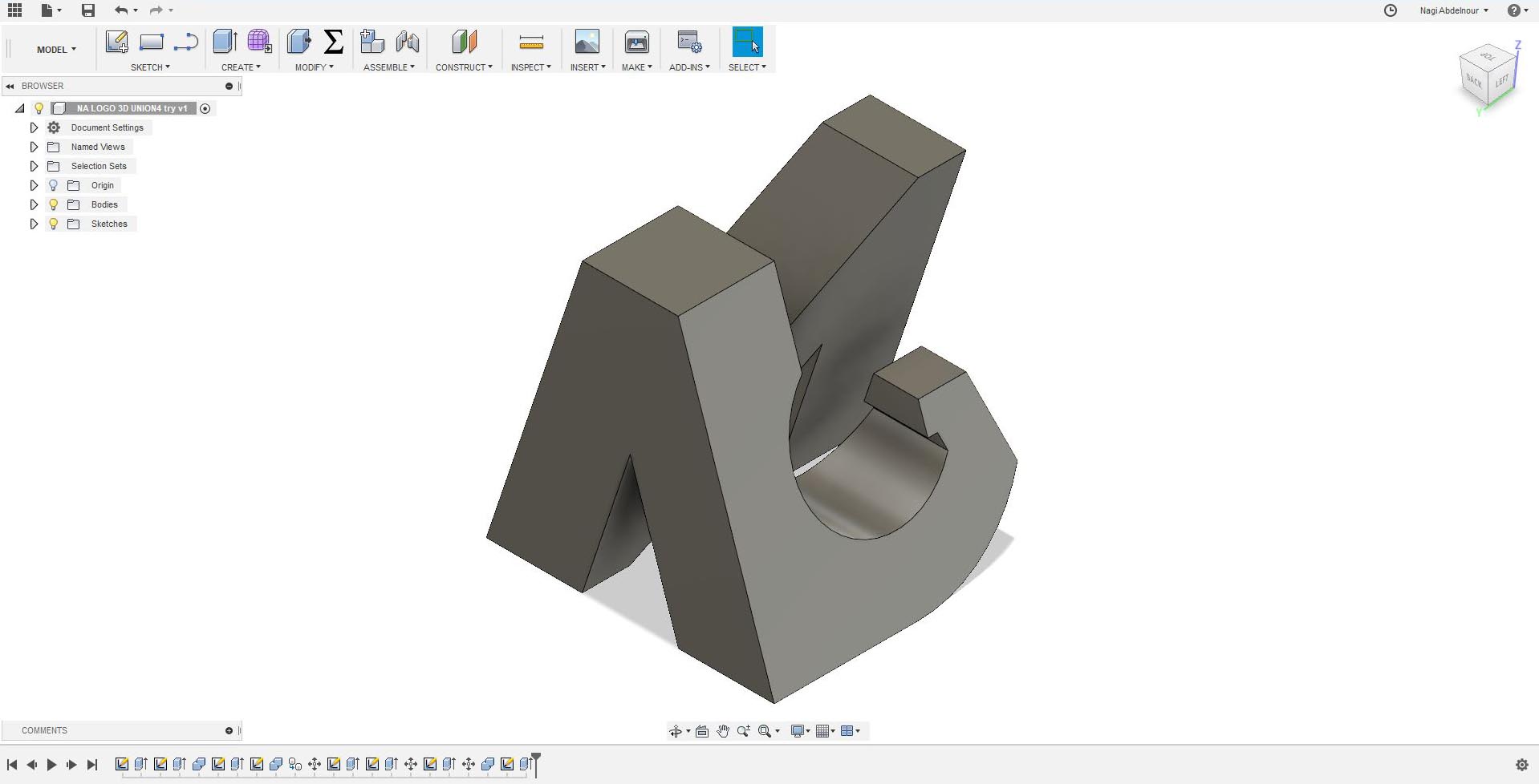
I will go now to the fourth face and sketch the letter I.
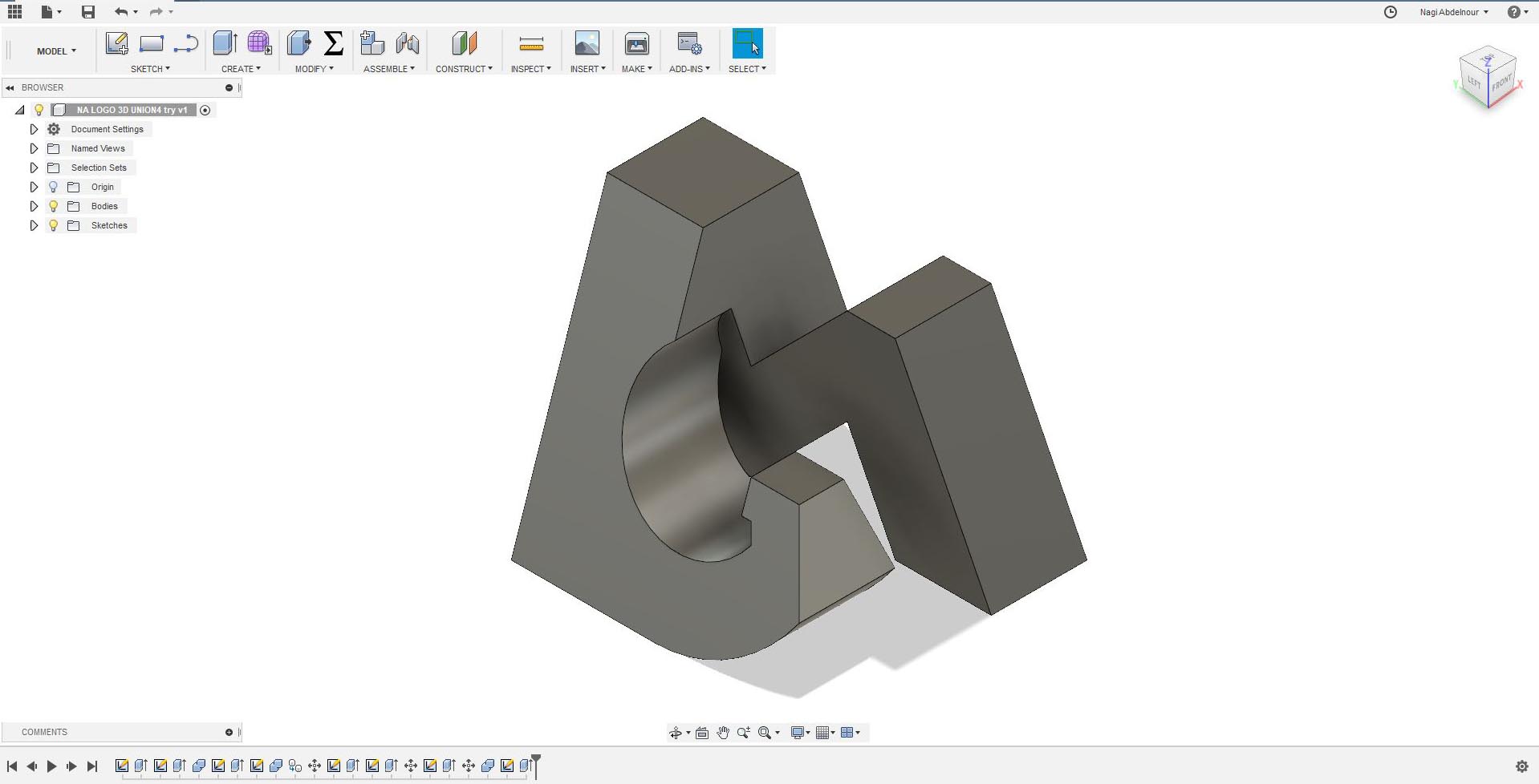
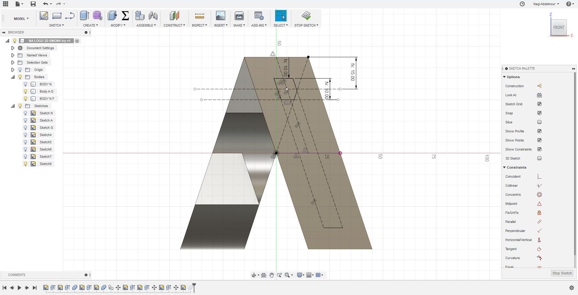
Finally subtract the point of the I...
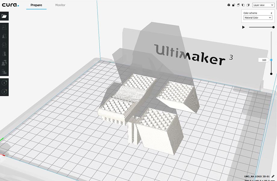
Printing
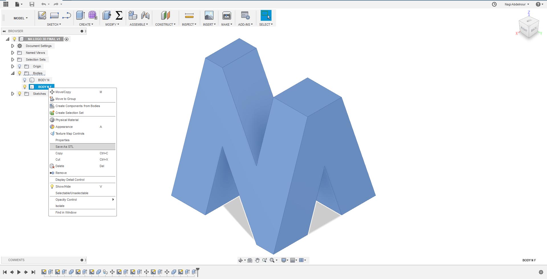
Now that I finished my design I have to prepare it for printing.
I will first export the model into STL file.
Then I will use CURA as the slicing software in order to generate the g-code for printing.
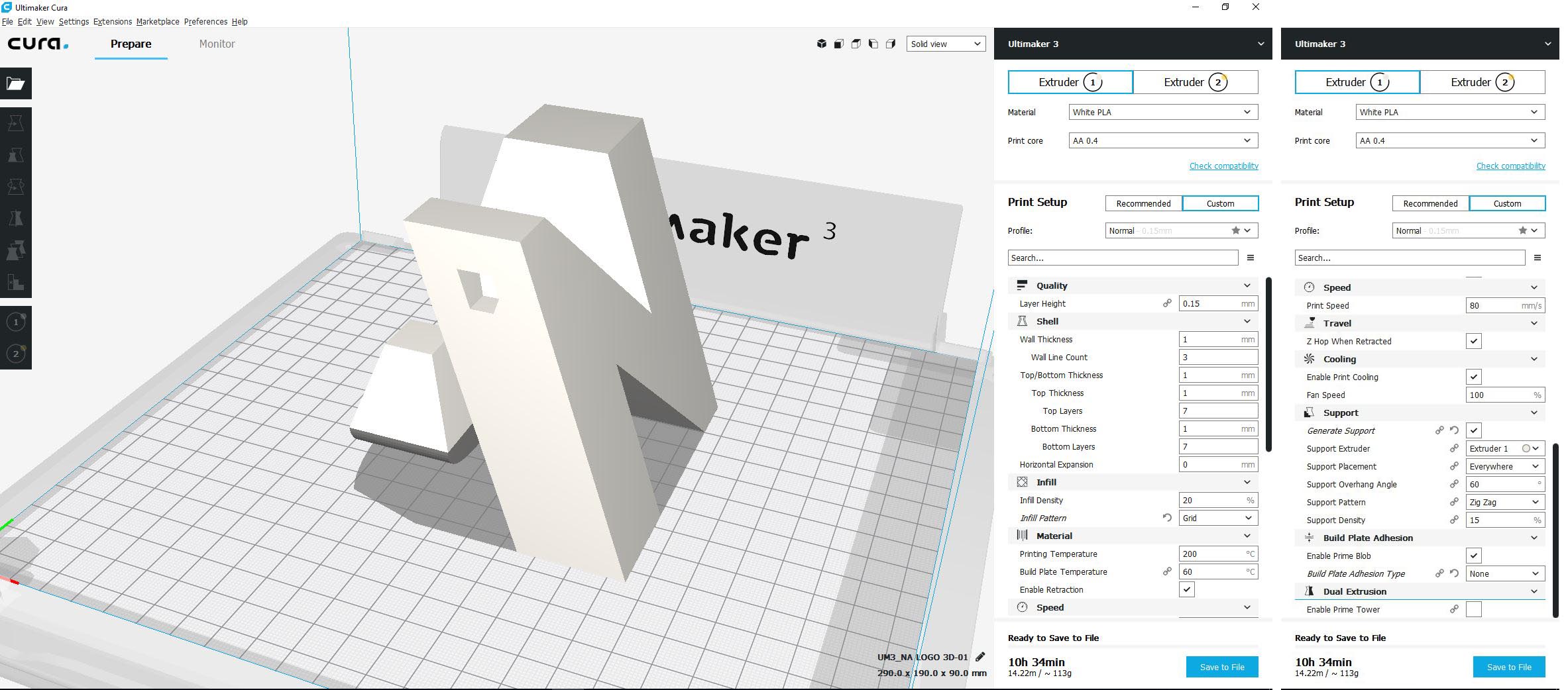
The settings used are the preset standard settings for a normal quality print with PLA filament:
- Layer height: 0.15mm
- Wall thickness: 1mm
- Infill Density: 20%
- Infill Patern: Grid
- Printing temperature:200degC
- Build plate: 60 degC
- Print speed> 80mm/s
- Support Overhang Angle: 60
- Support Patern: ZigZag
- Support Density: 15
- Build plate adhesion type: none
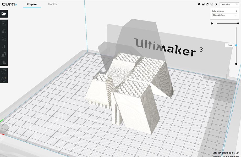
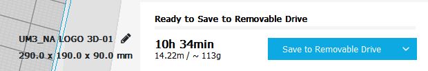
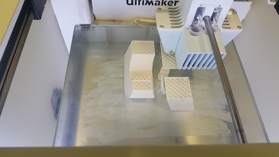
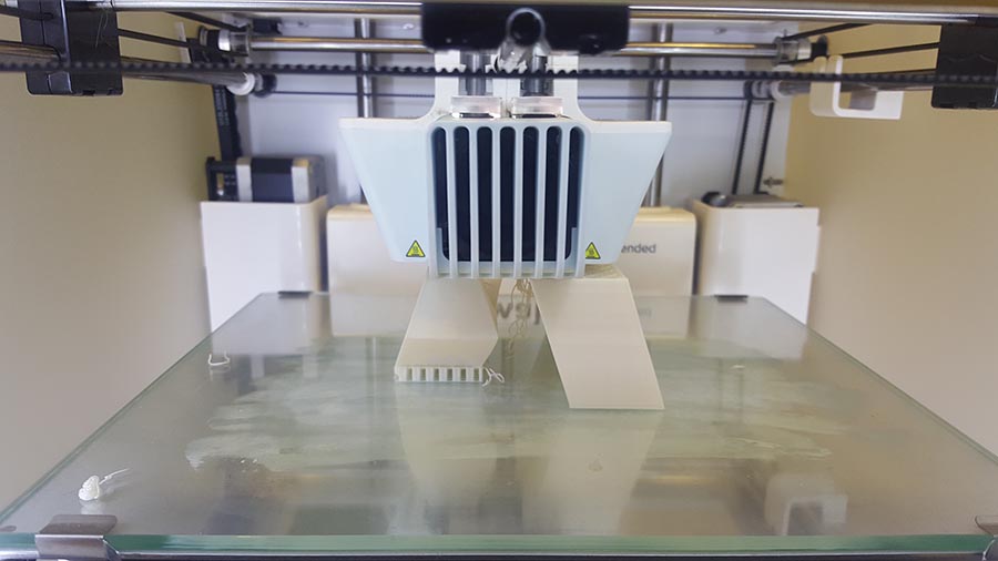
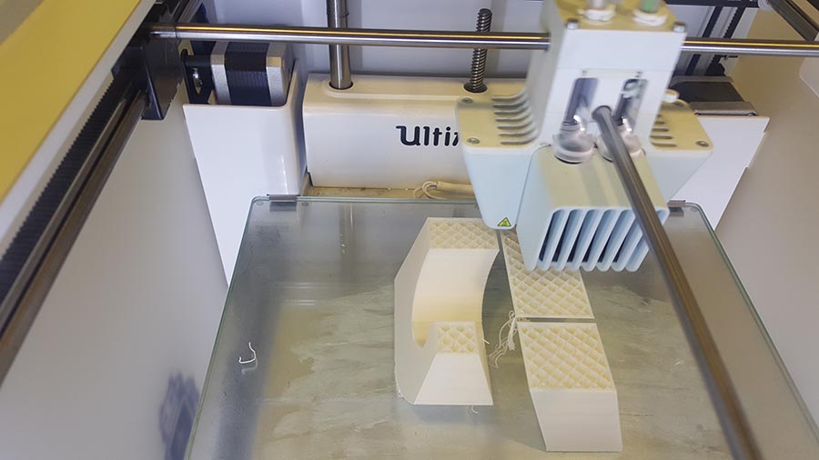
Once all the settings are done, we Save to Removable Drive.
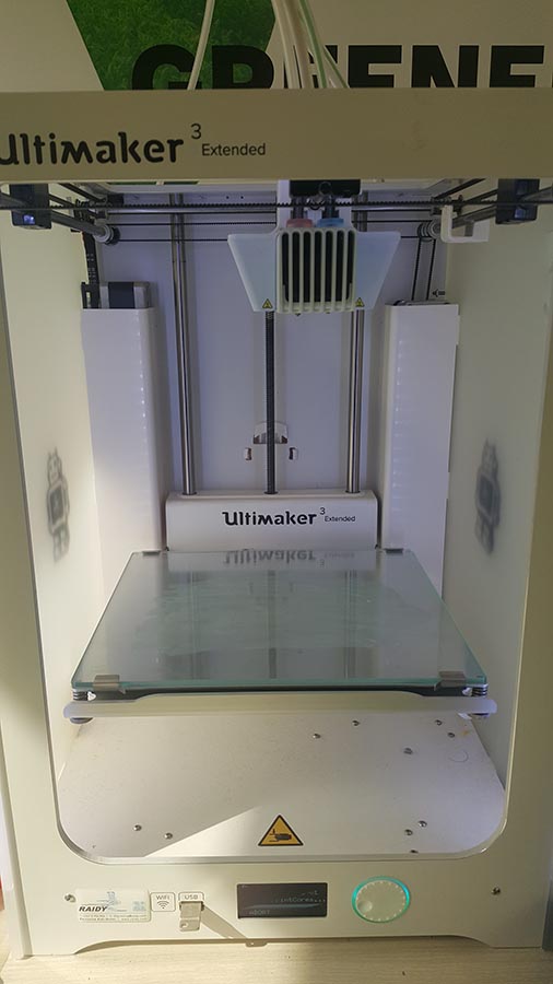
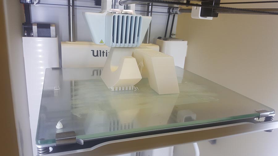
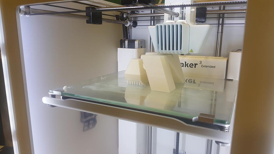
And plug the USB into the Ultimaker in order to start printing.
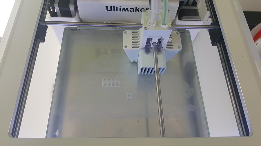
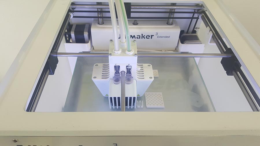
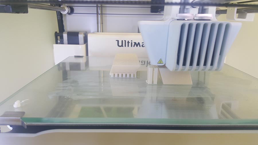
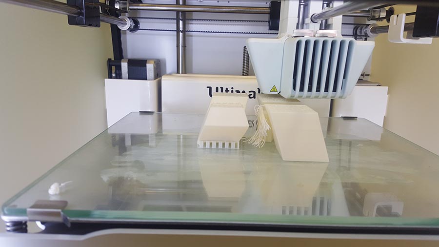
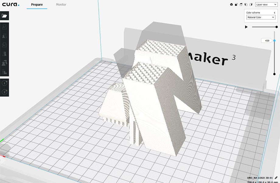
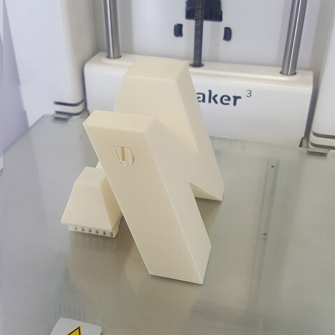
We can notice in the last image that the supporting structure have been moved from its place ,(we should have put a brim to make more adhesion to the plate) But in this case no damage have been made and the printing continues.
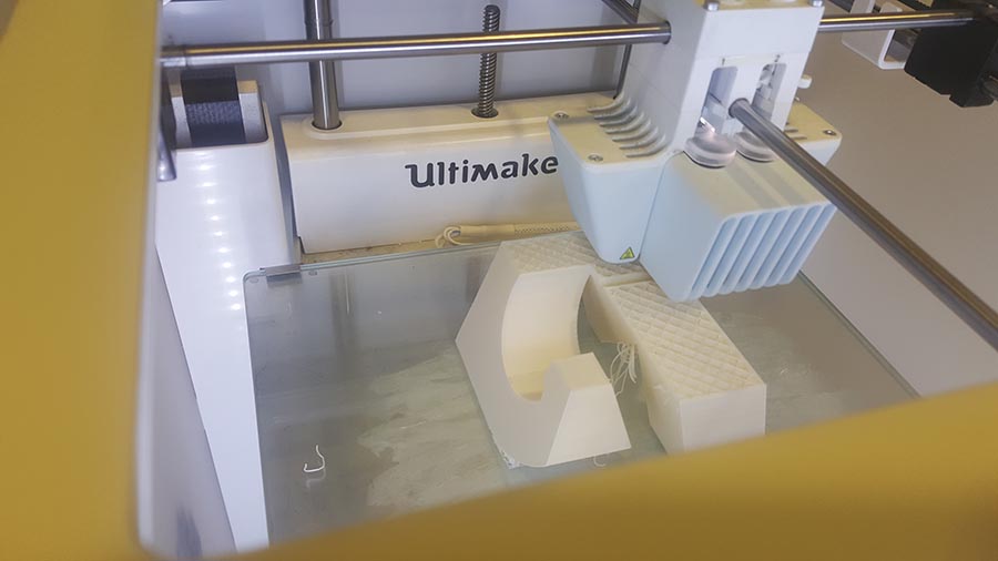
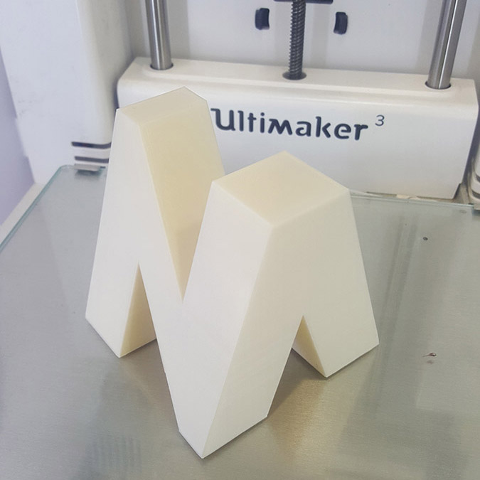
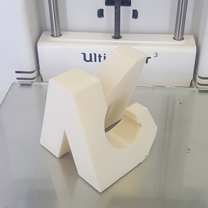
And the final result.
3D Scanning
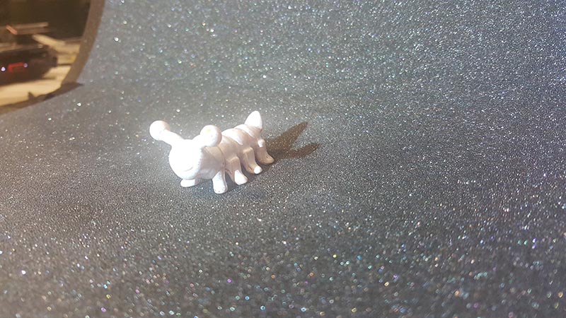
For this assignment I will use a small worm sculpture; It is interesting to see how we can transform a small object with all its details to a 3D digital format and try eventually 3D print it on a bigger scale or even on a very big scale if we want.
But the Problem was that the worm object is in yellow and the colored surface couldn't be detected easily by the scanner.
So the Solution was to paint it in white and make it more visible to the 3D Scanner we are using.
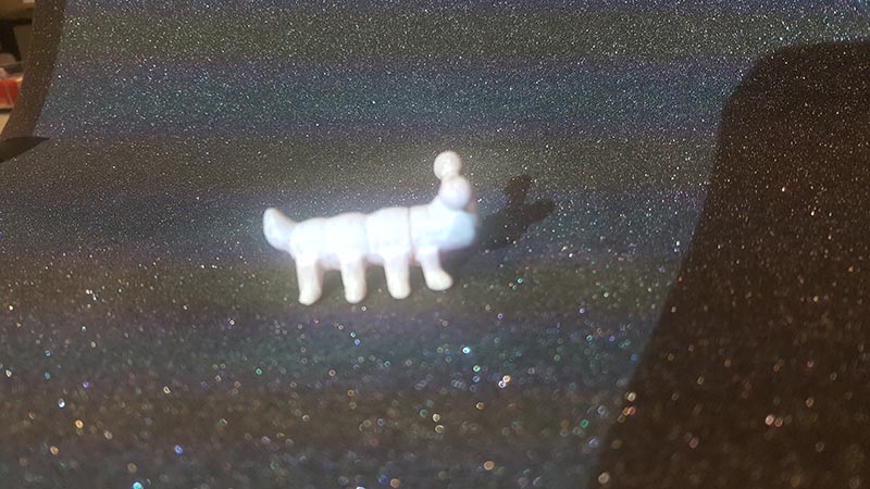
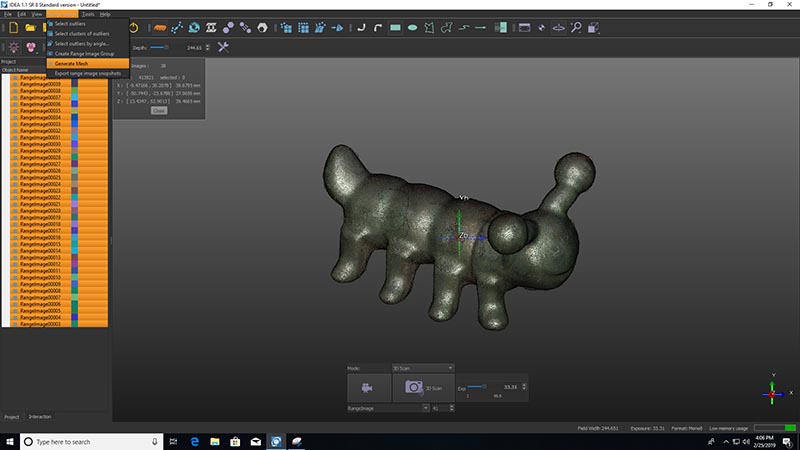
After setting the black background and placing the object in front of the scanner.
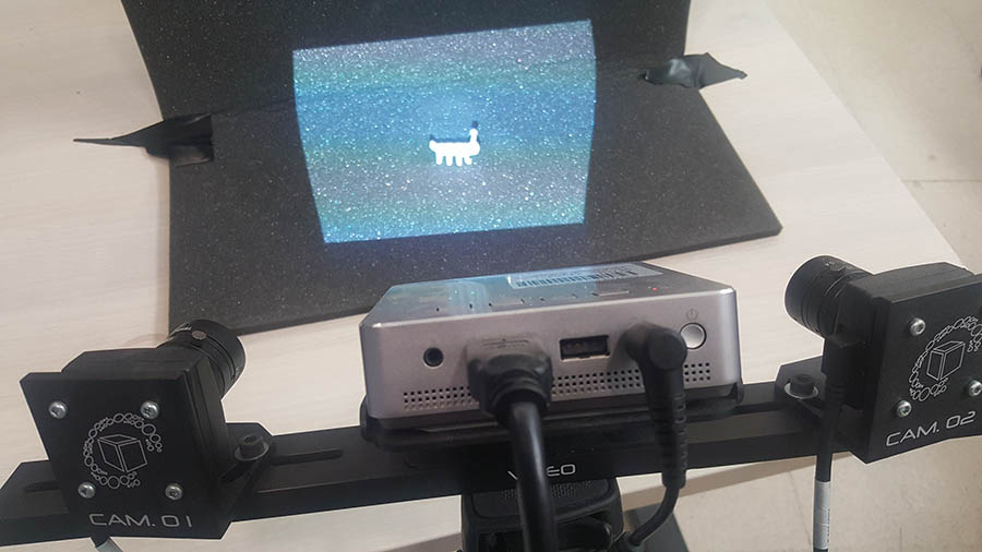
We start taking photos from all the different angles of the object using the special scanner software.
After that we have to recombine these photos into one mesh.
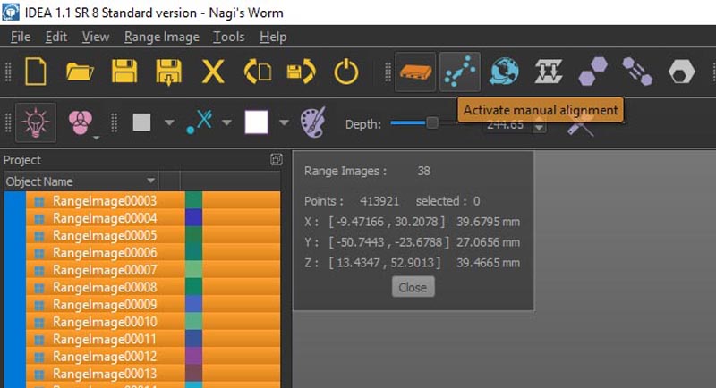
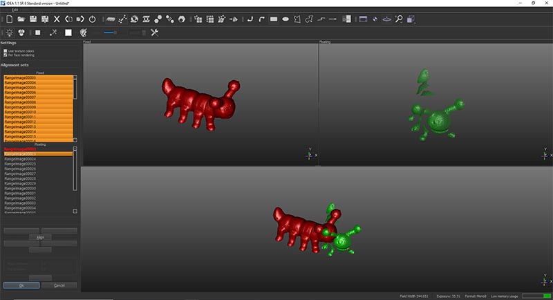
For that we have to align all the images (in green) to the main image (in red) by placing a point on the red image and it's similar on the green one. We do this for three points.
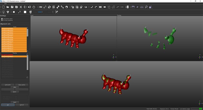
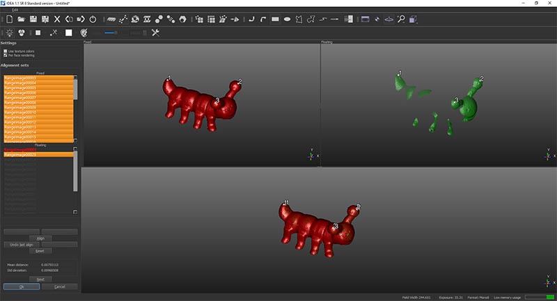
After that we press align than press next to do the same to the following image.
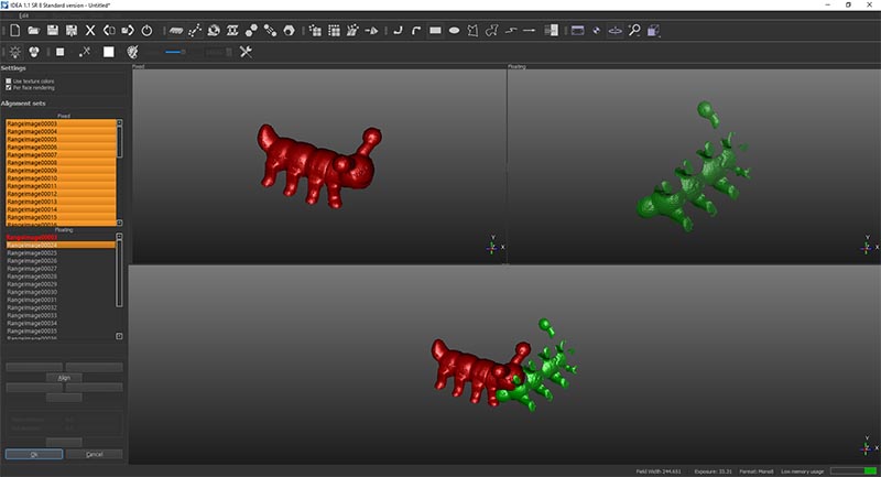
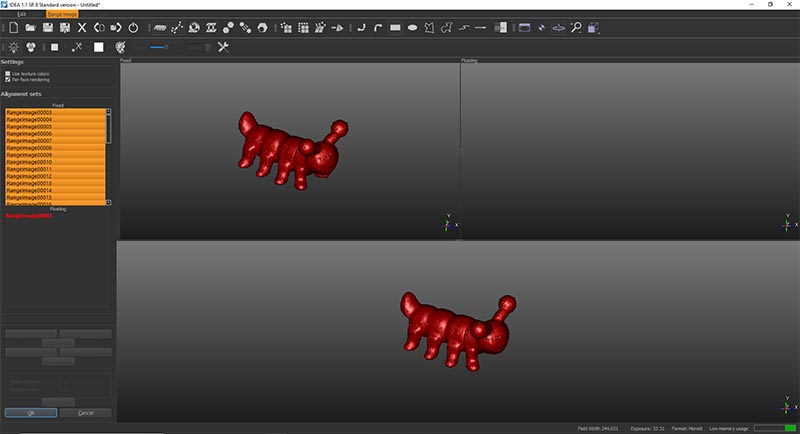
Once it is done for all the images and there is no missing parts in the model, we start generating the mesh.
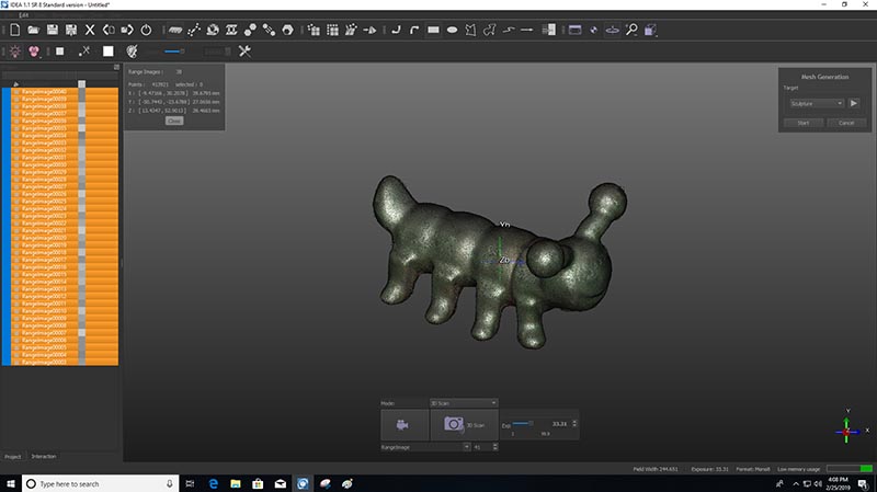
Now that we have the mesh we can export it into an STL file for printing.
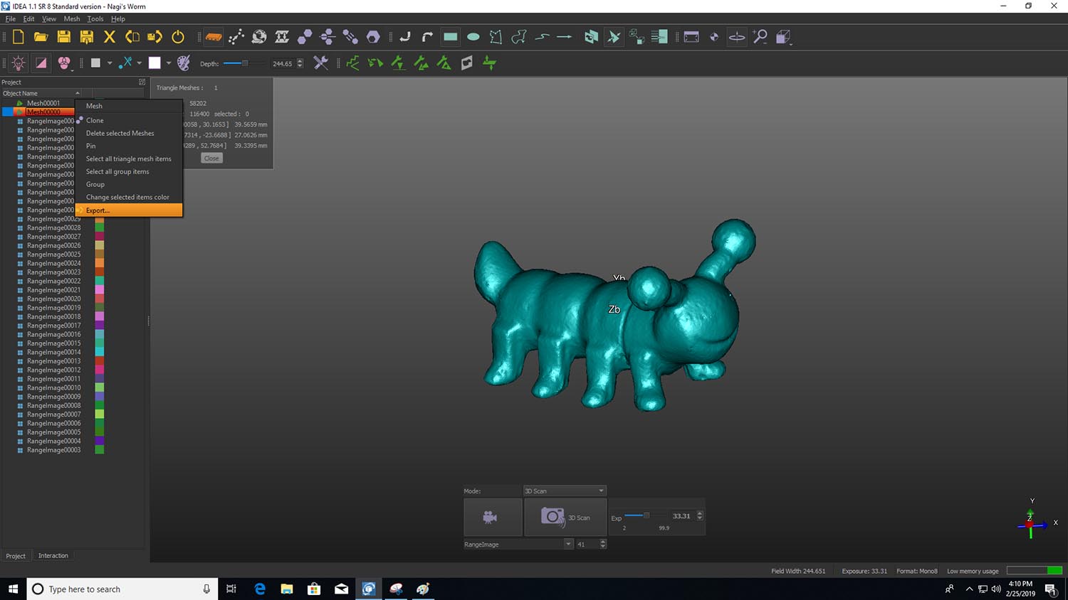
Finally I open it in Fusion to be able to share it.
Files
Click Here to download my Design Fusion File
Click Here to download my Design STL File
Click Here to download my Design Cura File
Click Here to download my Design g-code File
Click Here to download the 3D Scanned STL File