Assignment
Model (raster, vector, 2D, 3D, render, animate, simulate, ...) a possible final project, and post it on your class page
Using Photoshop
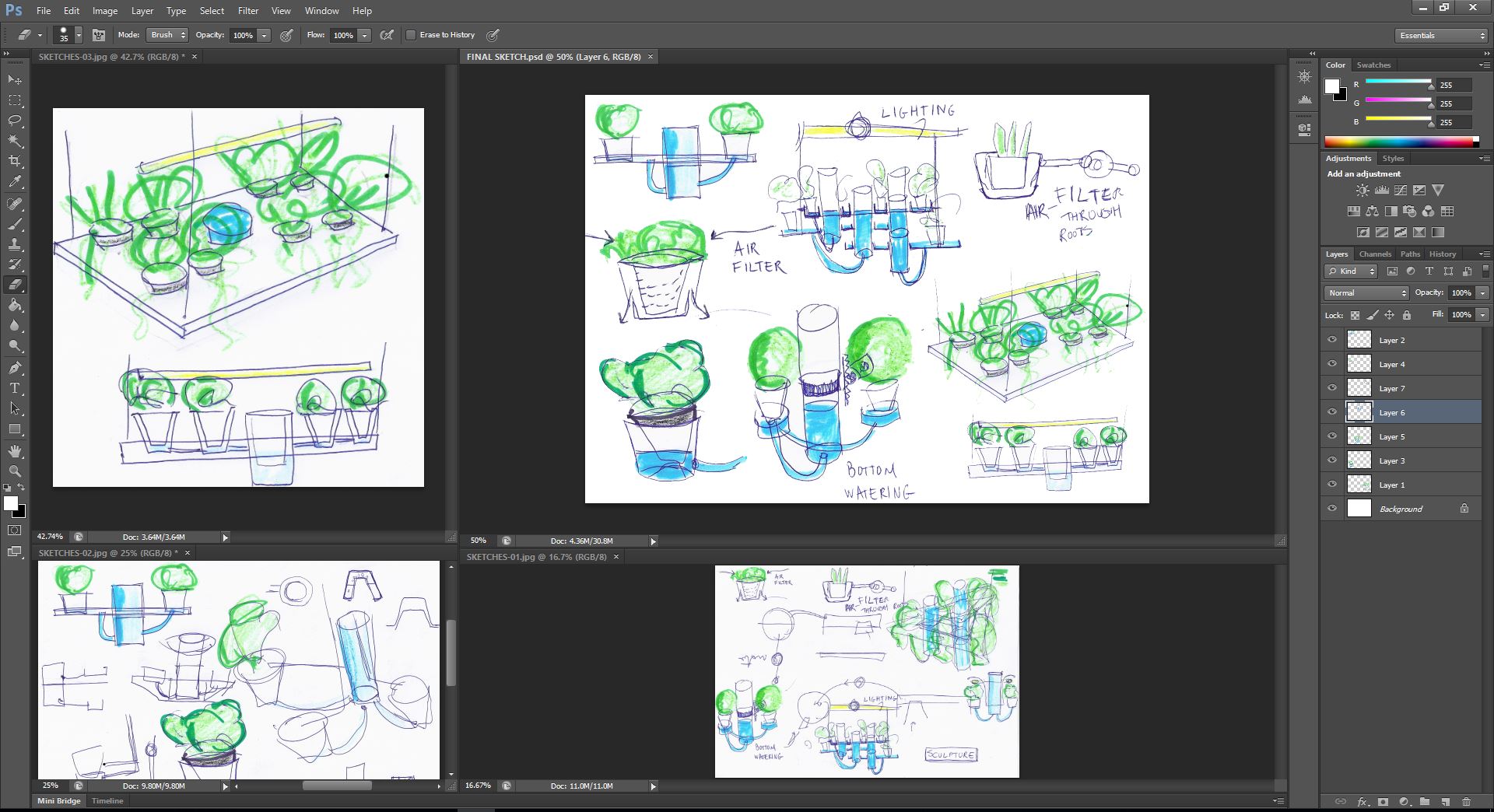
I will use Photoshop software to scan my hand drawn sketches and adjust them and put them in a single Moodbard Image
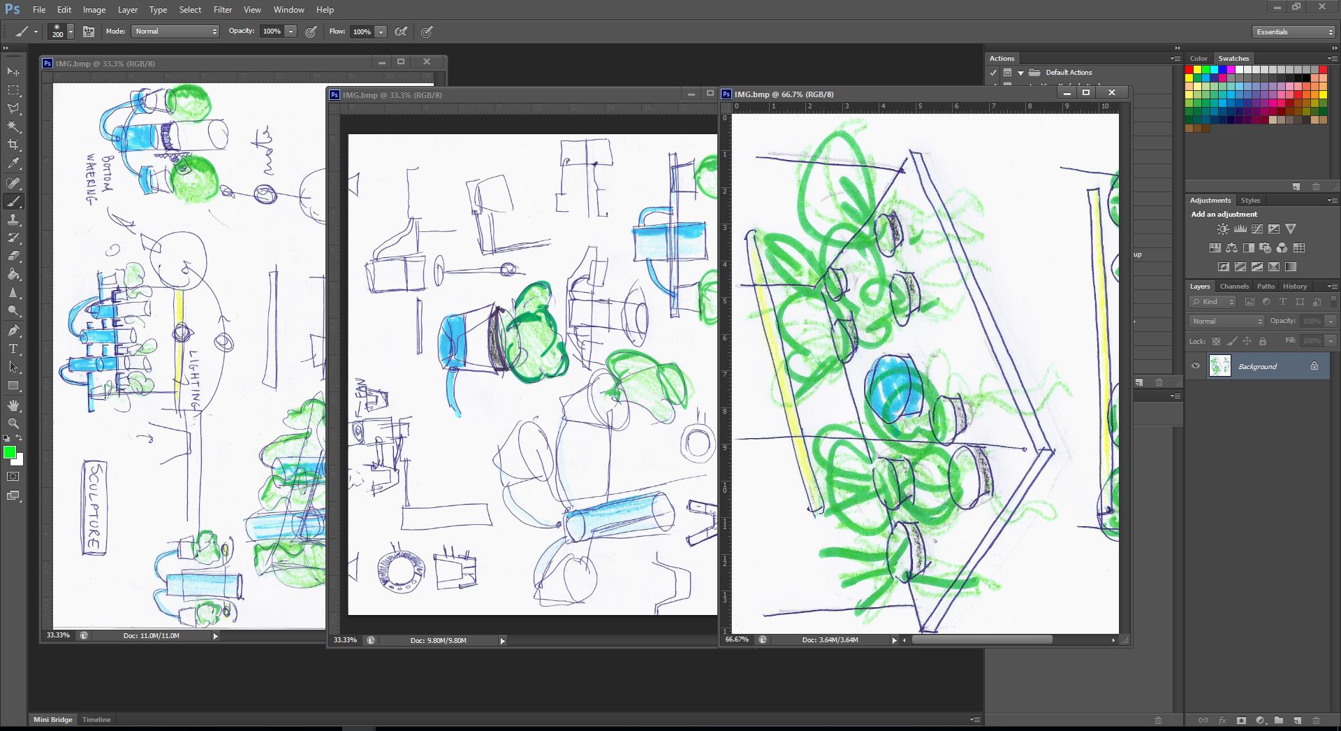
I adjusted the rotation of the scanned images , created a new image and dragged parts of the scanned sketches to the new created moodbard image
Using Autocad 2D
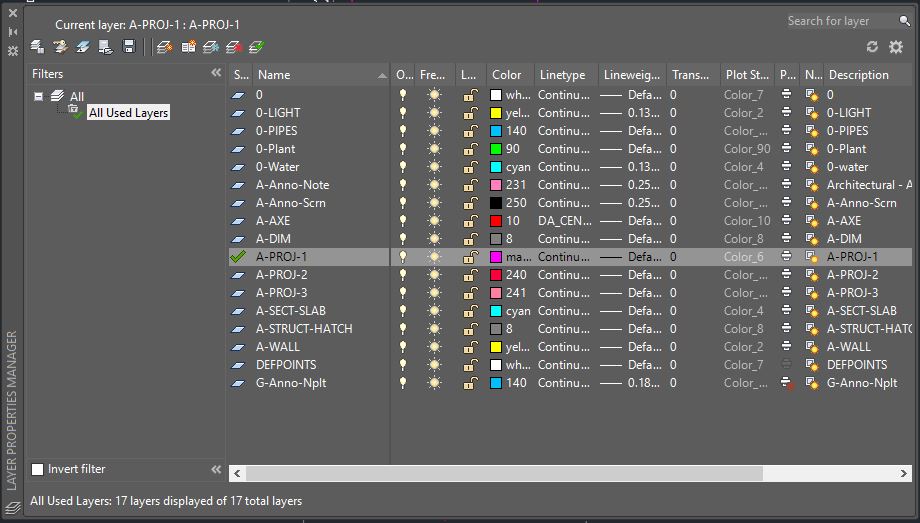
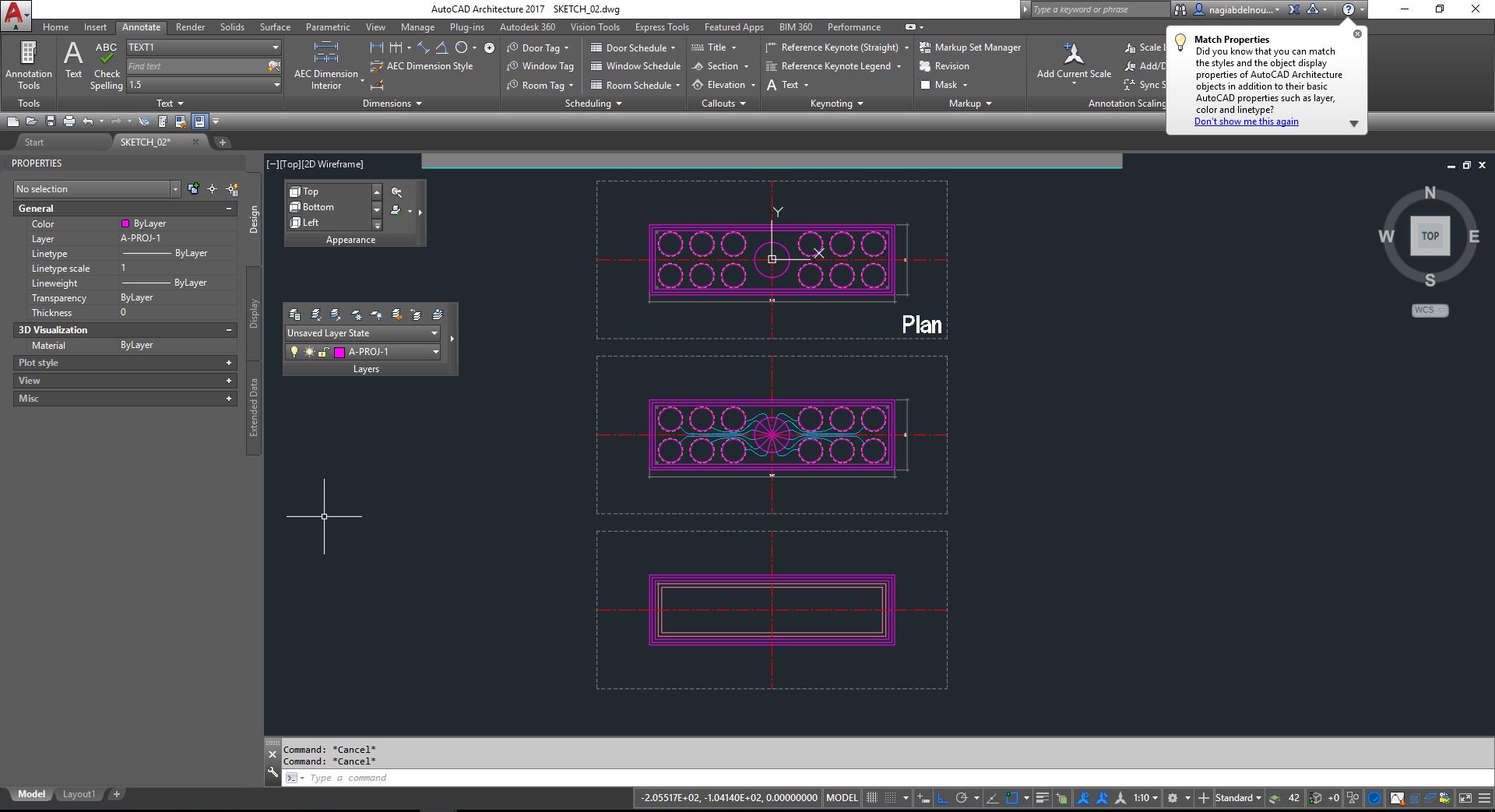
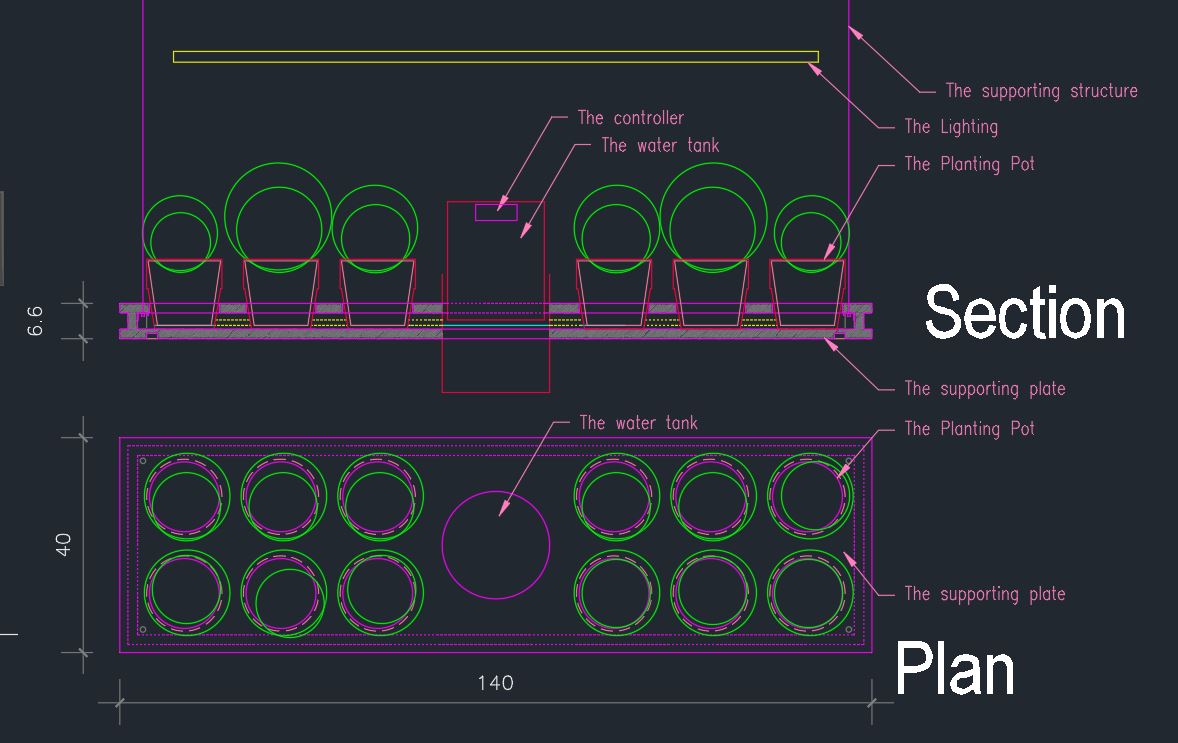
Based on the moodbard image, I will use Autocad software to draw a section and a plan for my final project .
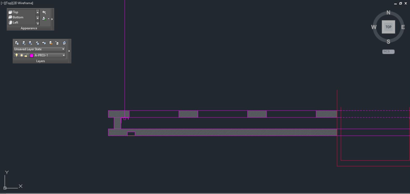
For that I start by creating different layers with different color which I will use to recognise each part, than I will start drawing using mainly the following commands:
- Line
- Copy, move
- Offset
- Trim, extend, chamfer
- Hatch
- and the F8 key to change from ortho mode to free mode
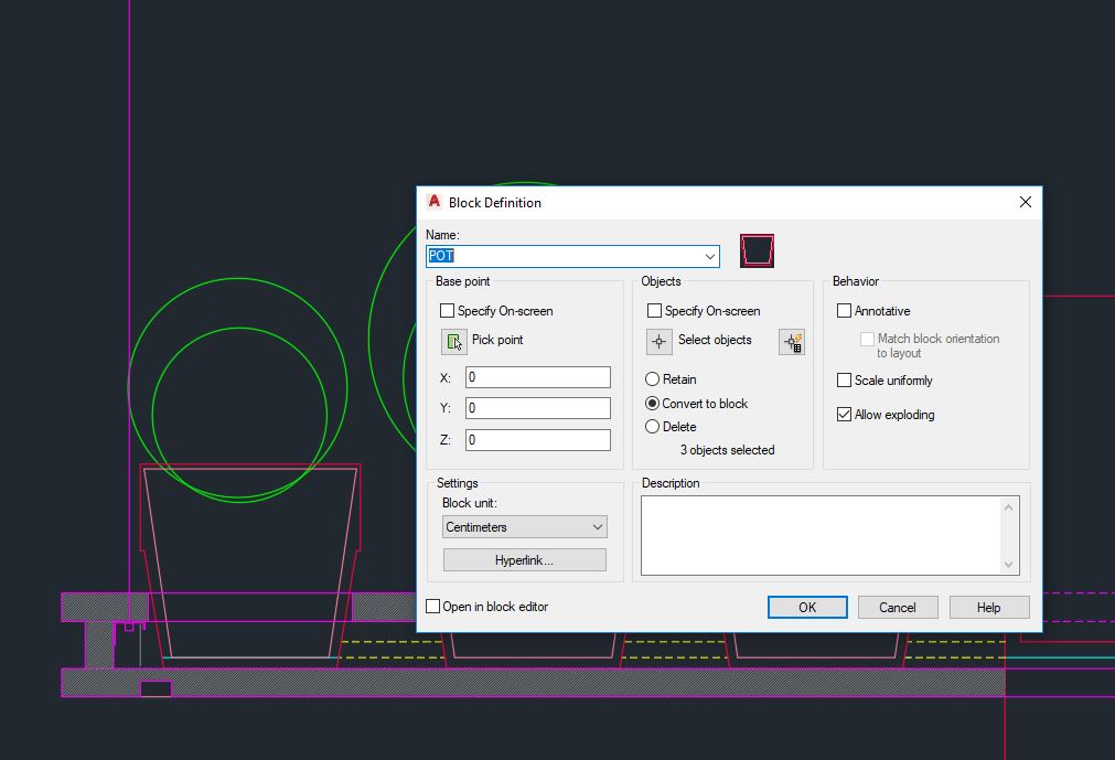
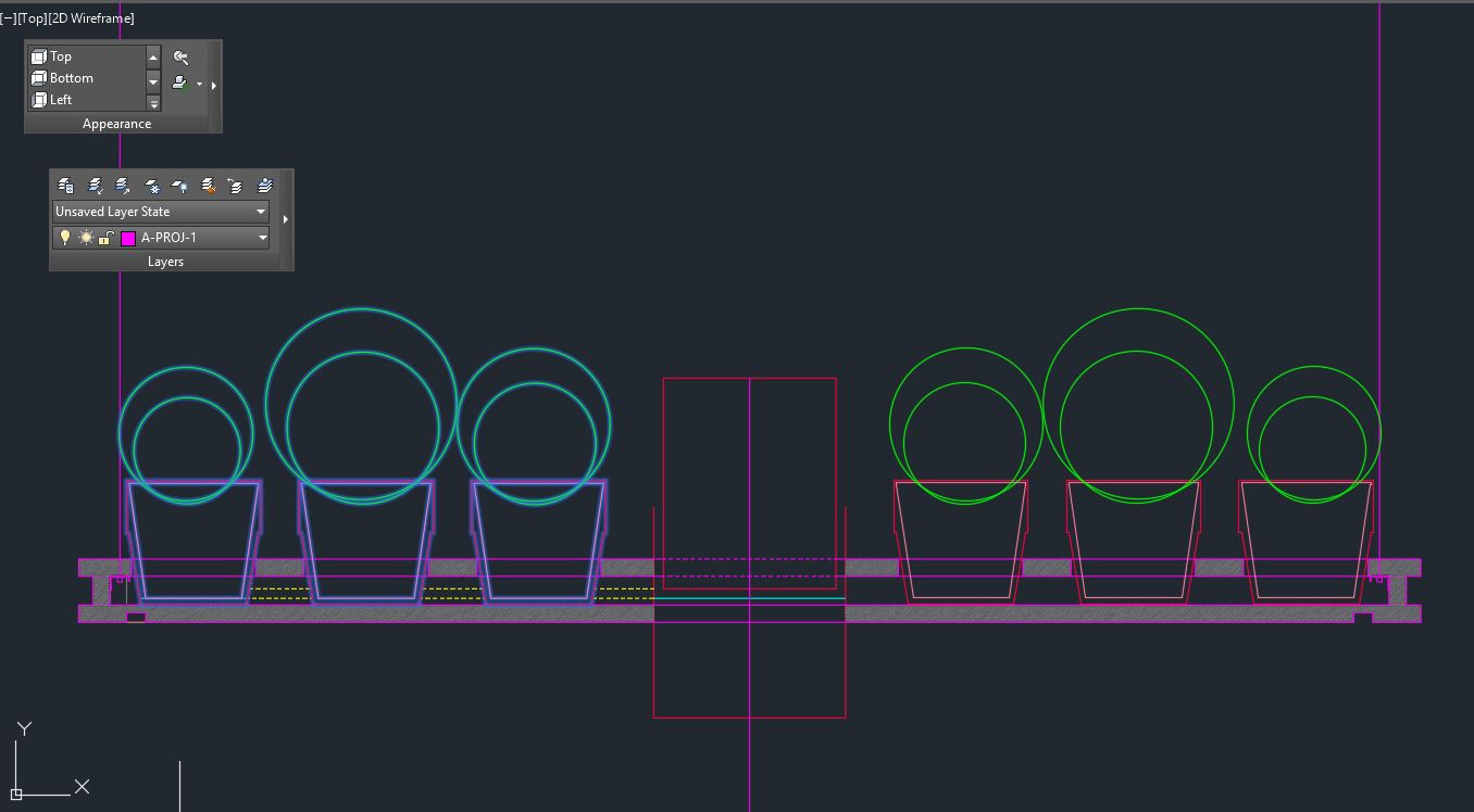
Next I will make a block for the plant pot before I copy it (in order to modify it whenever I want) than I will use the mirror command to finsh drawing the other identical part
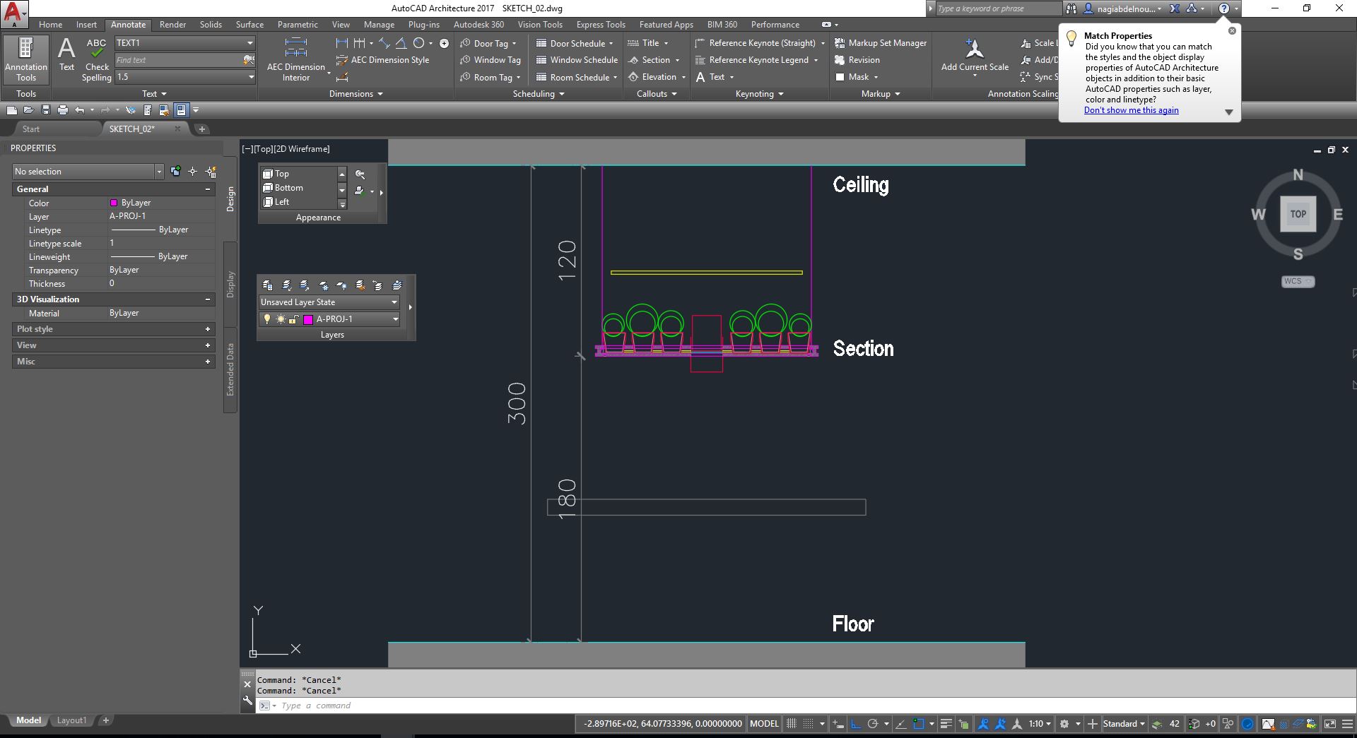
Now I have a clearer idea of what my final project will look like with its approximative dimensions, and it will include the main following parts:
- The supporting structure
- The lighting
- The controller
- The water tank
- The planting pot
- The Supporting plate
Using Autodesk Revit Software
What is Revit?
Autodesk Revit is Building Information Modeling (BIM) software, which allows the user to design with parametric modeling and drafting elements.
Building Information Modeling (BIM) is a new Computer Aided Design (CAD) paradigm that allows for intelligent, 3D and parametric object-based design. In this way, Revit provides full bi-directional associativity. A change anywhere is a change everywhere, instantly, with no user interaction to manually update any view.
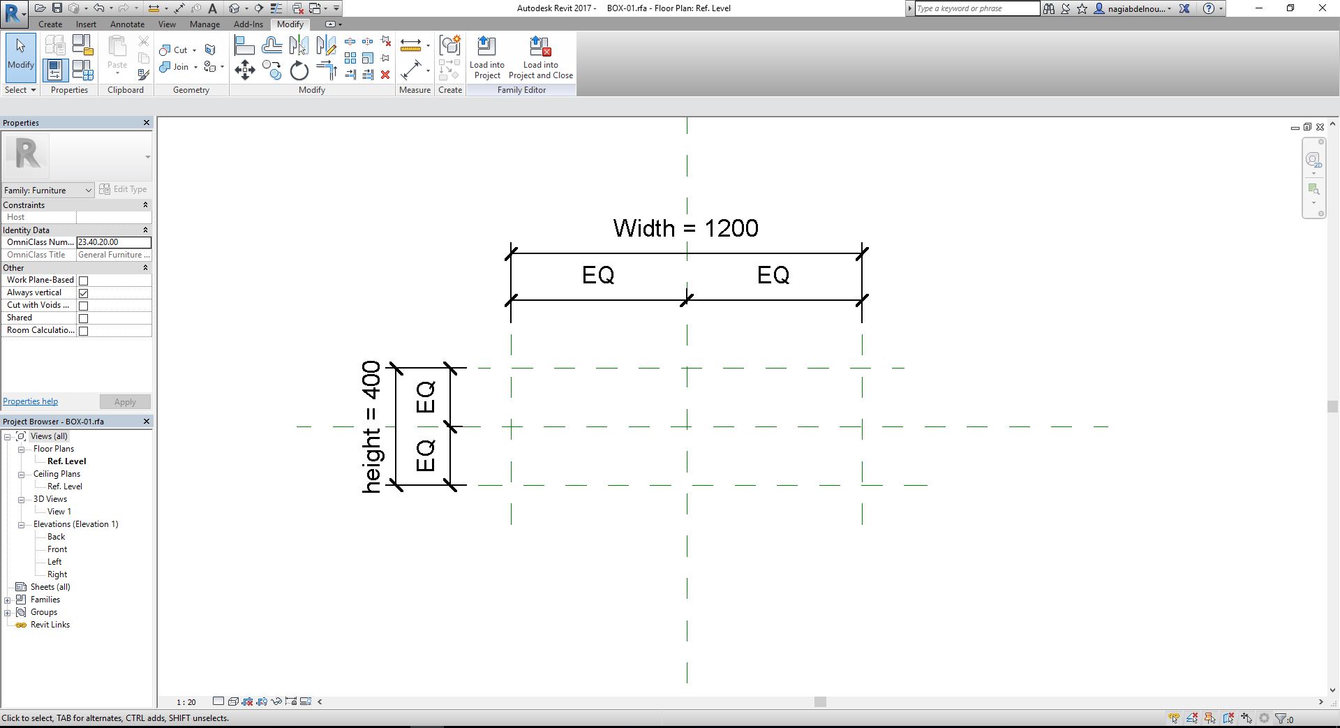
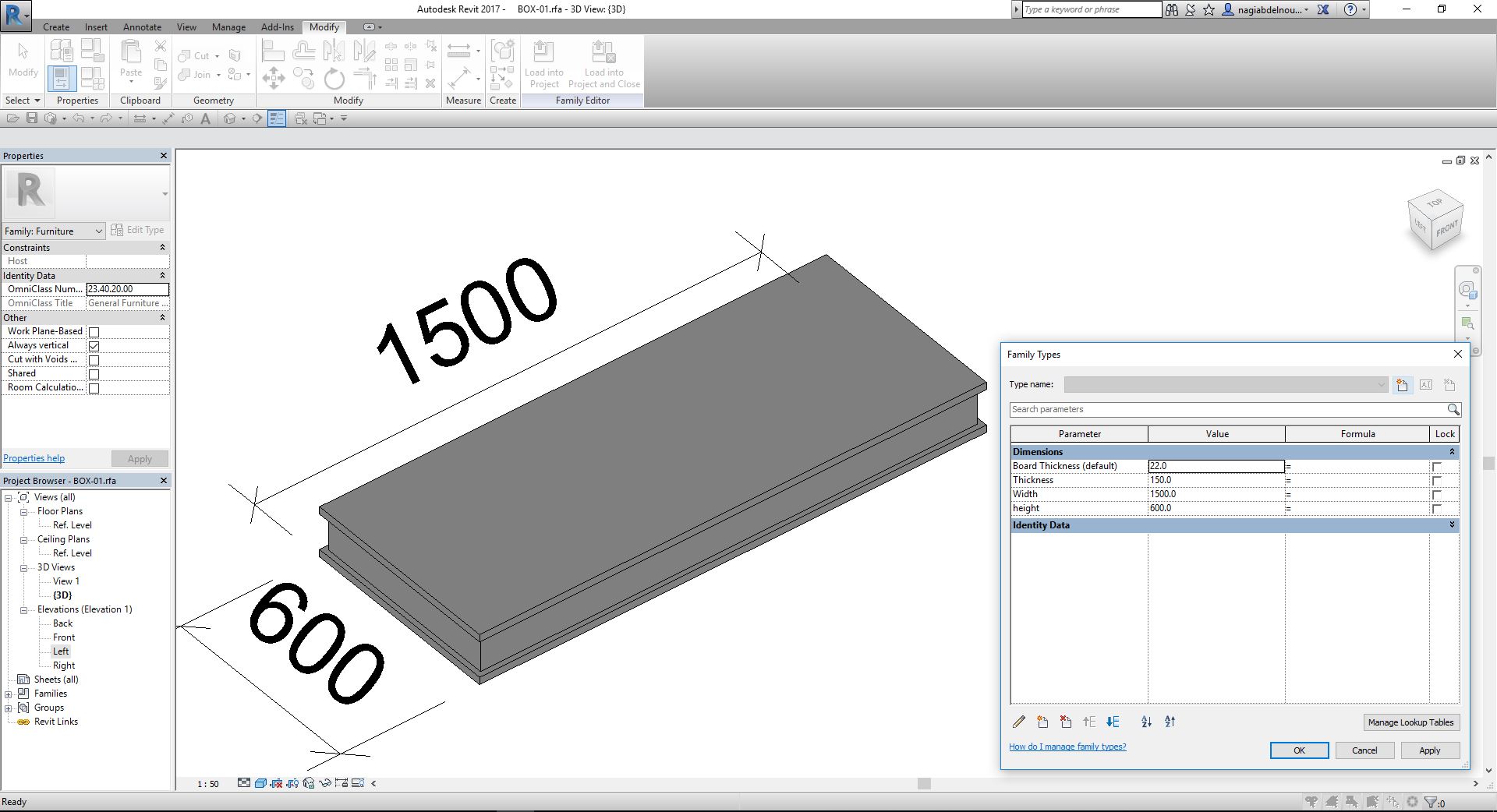
I will use Revit software to model my final project. First I will create a new family file and set reference planes with dimension parameters for the Width and the Height.These reference planes will be the guidelines for all the 3D objects I will be modeling and I will be able to change the dimension parameters (width and height) whenever I want.
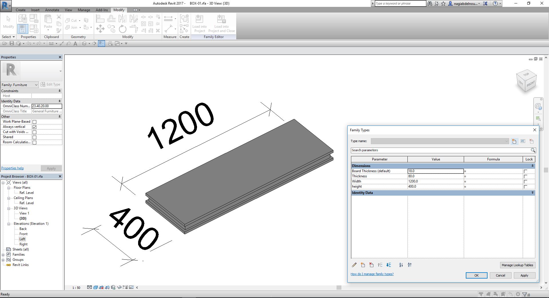
In the following steps I will create 2 rectangular boxes one above the other with a board thickness parameter(Board Thickness=18) and added also a total thickness parameter for the 2 boards(Thickness=100).I will create also a frame between the 2 boards with the same board thickness.
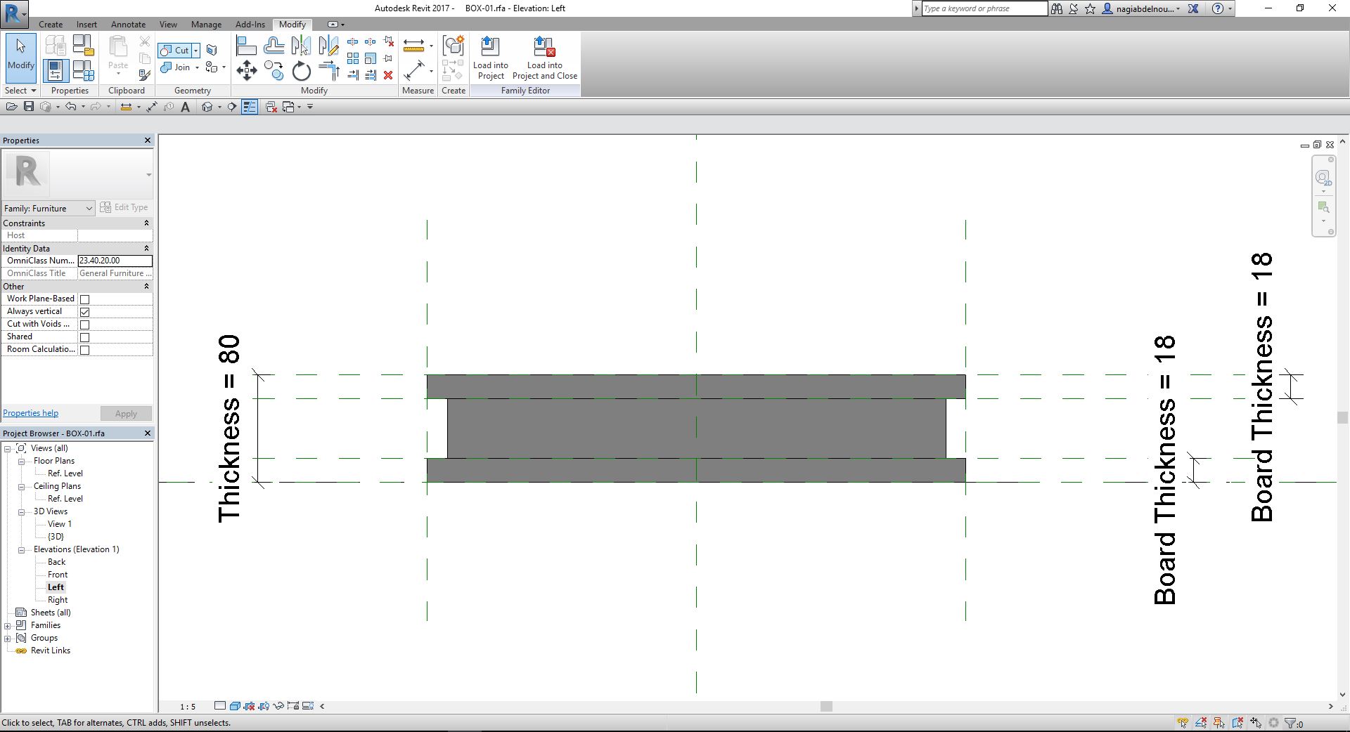
Now I can change the width, the height, the thickness and the board thickness.
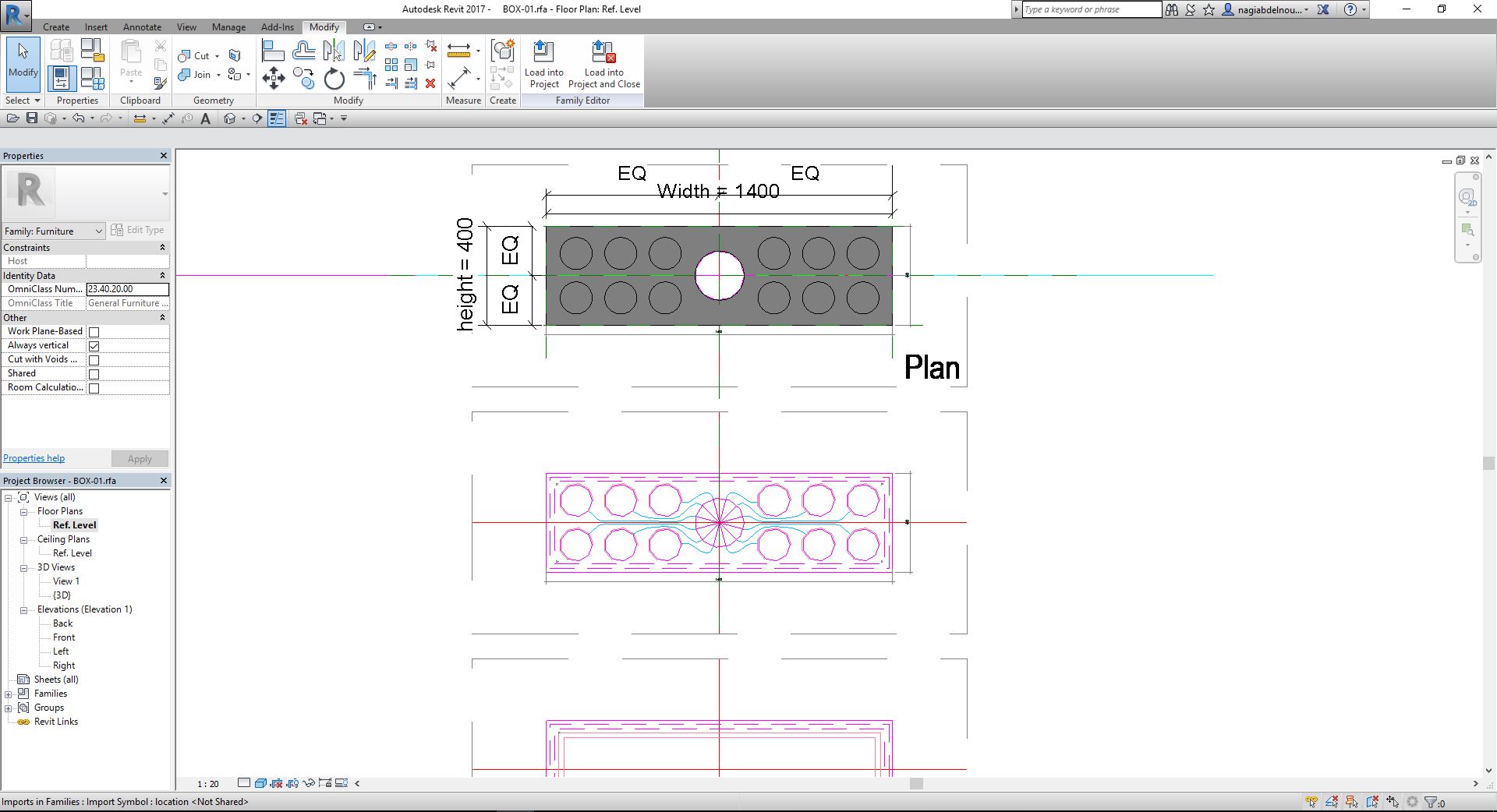
In the following steps I will import the 2D autocad plan and section to revit and place them in their respective views. Now I can create the pot opening in plan by creating a solid void(I gave the circles a parametric radius in order to control them when I want).In the section I will be able to trace the pot profile.
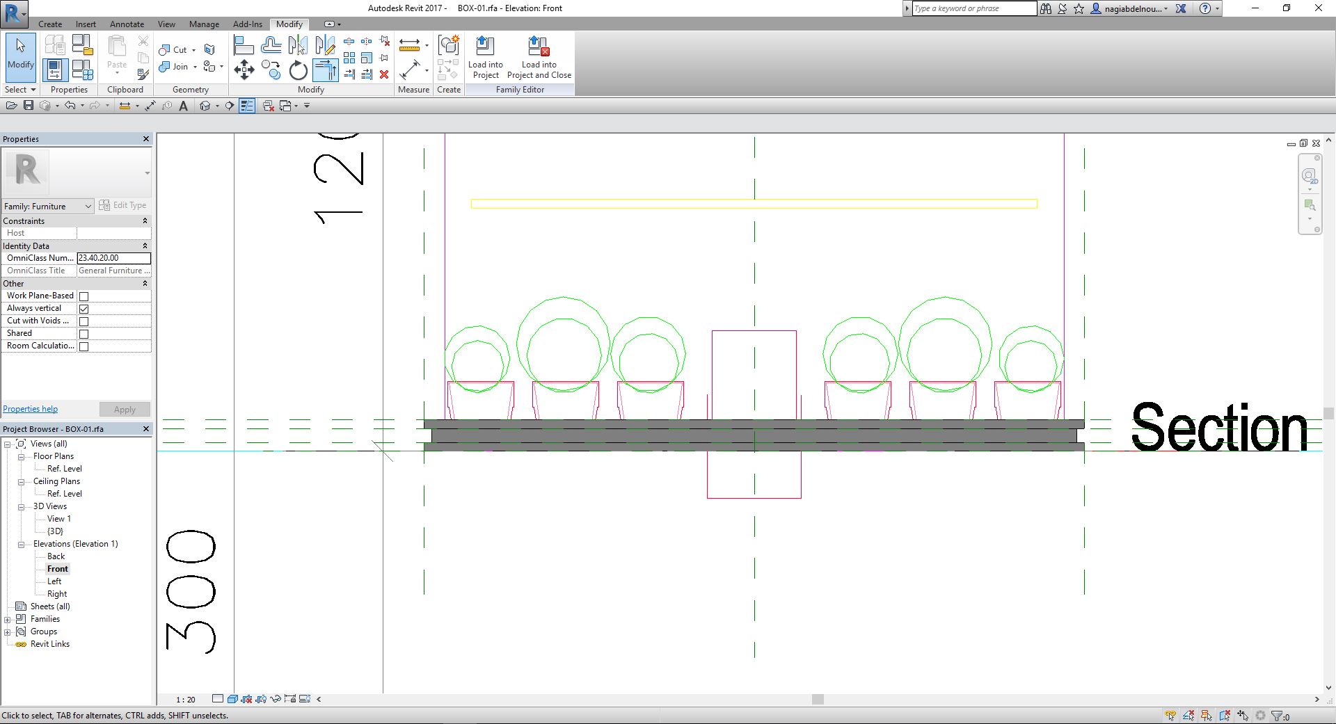
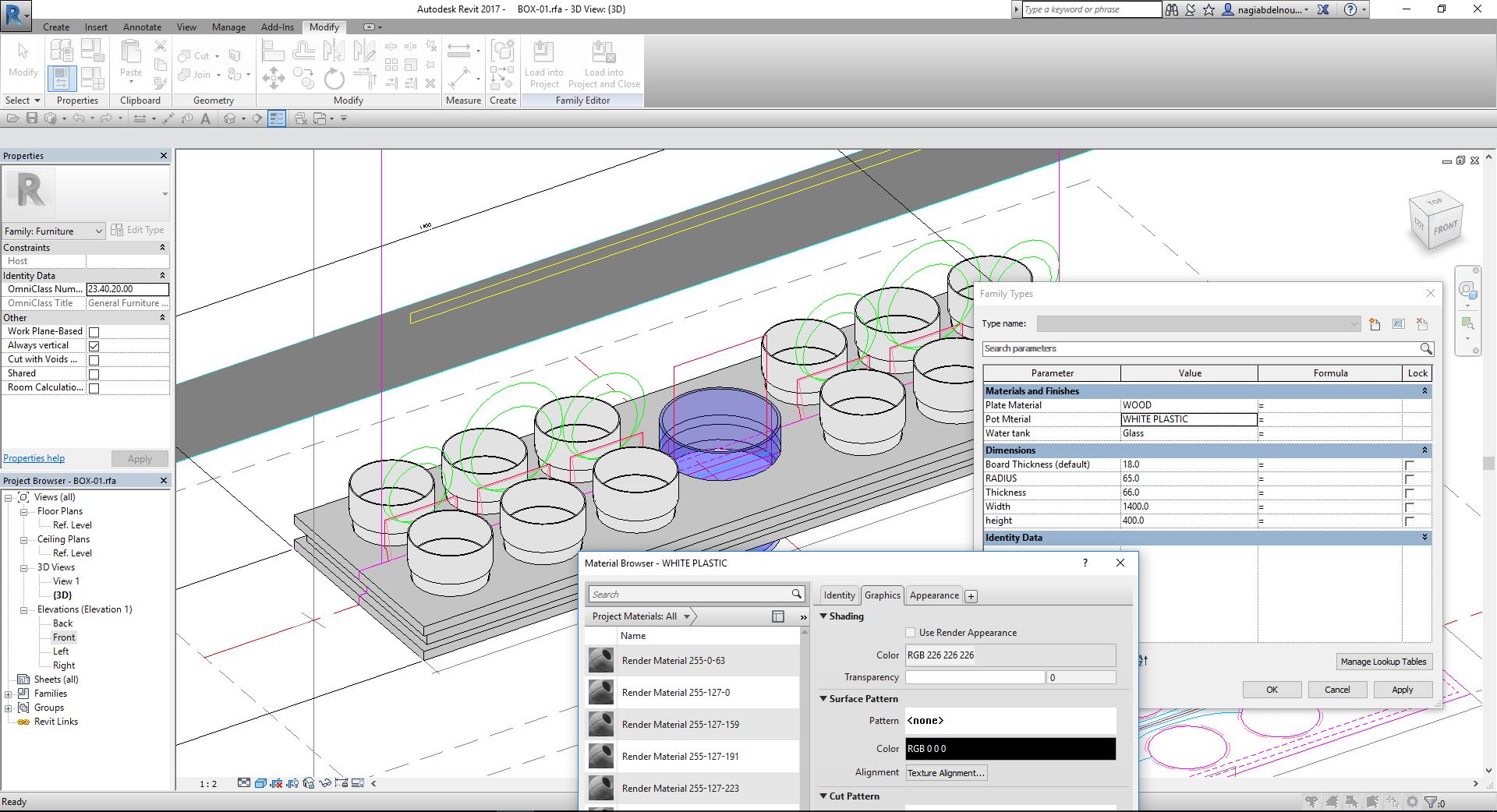
After retracing the pot profile from the 2D autocad file I will revolve it to obtain the 3D model than give it a material parameter.

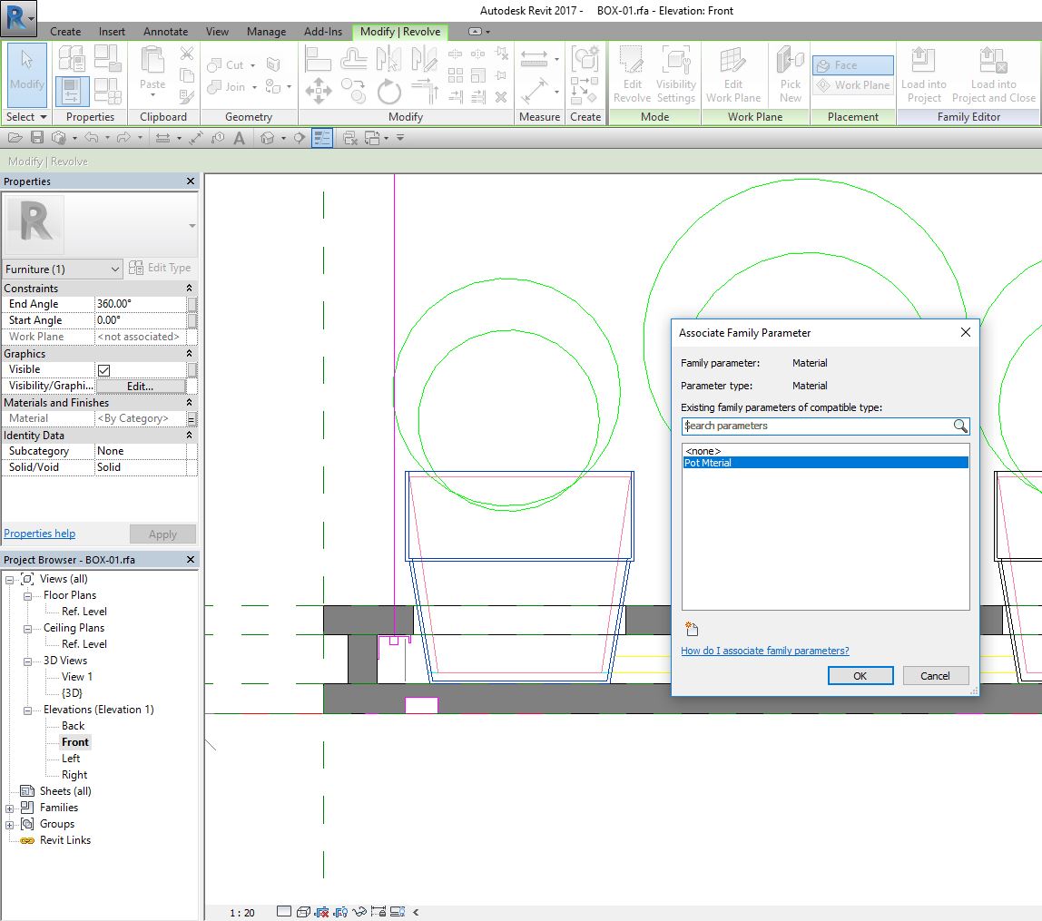
I will do the same to the water tank than define a material for each parameteric material in the material browser.
Next I will model the inner pots and the supporting structure.
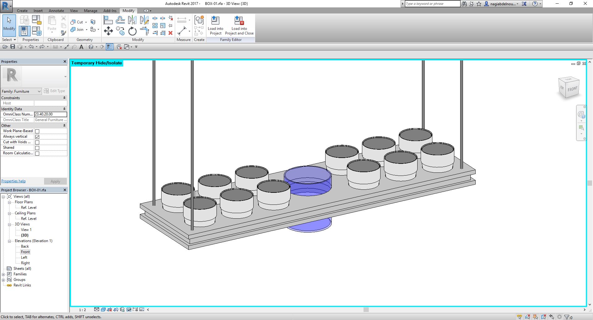
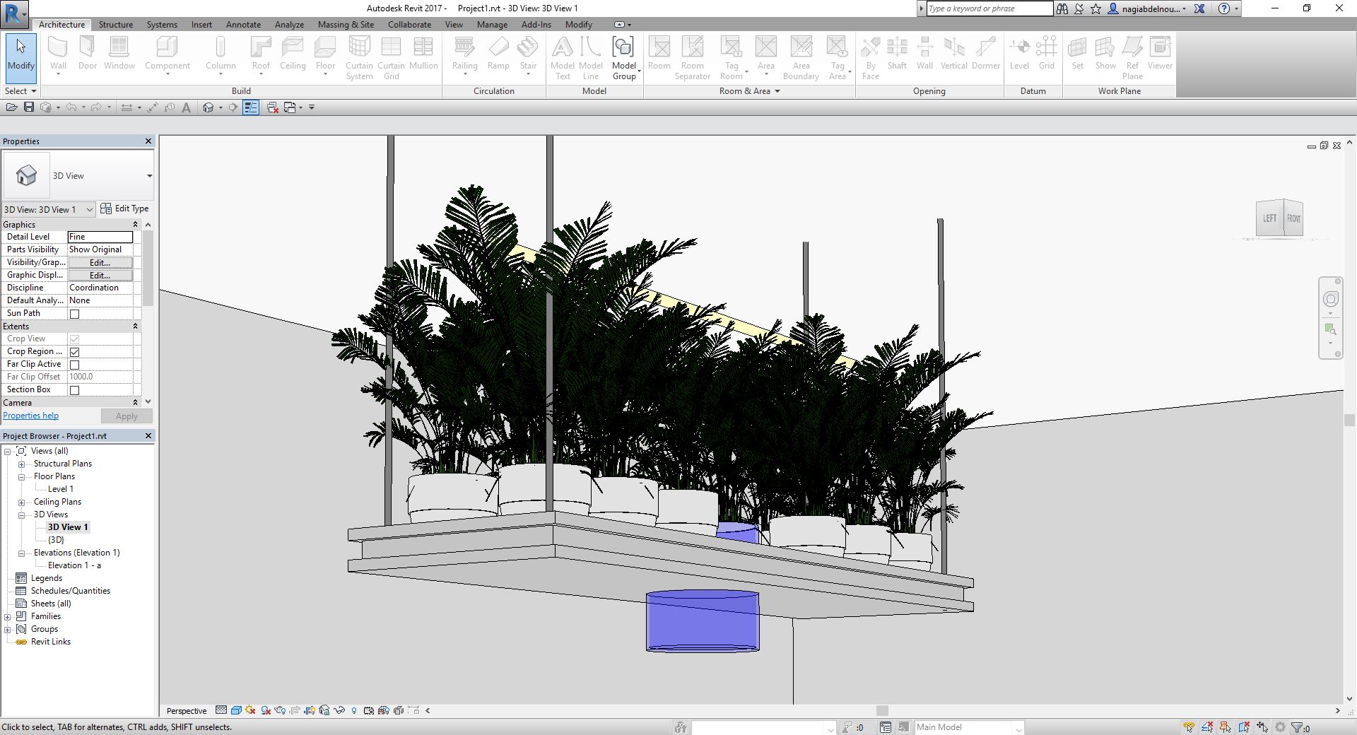
Now that I finished modeling my object in the revit family section I can now load it in my next future projects and adjust each parameter accordingly.
Summary
I have used photoshop to create a moodboard based on the initial hand sketches. On Autocad I converted the moodboard ideas into 2D drawings with initial dimensions, than I used the 2D drawings in Revit to 3D model my project with parametric data in order to adjust and modify according to my needs
Files
Click Here to download all the Design Files