Assignment
individual assignment:
measure something: add a sensor to a microcontroller board
that you have designed and read it
group assignment:
probe an input device's analog levels and digital signals
Individual assignment
For this assignment I will test some sensors I will be using in my final project.
The microcontroller that will be used in my final project is the ATmega328P , it is the same one used in the ARDUINO Board, so the testing in this assignment will be made using the ARDUINO.
The sensor that will be tested are the following:
- Push button
- LDR sensor
- Water level sensor
- Soil moisture sensor
- Temprature and a humidity sensor
- Clock module
1-Push button
Push button code 1
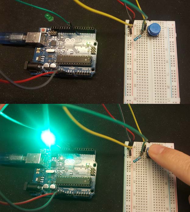
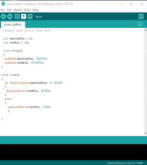
Below is a simple push button code : when we press the button the LED will turn on and when we unpress the button the LED will turn off.
                            /*simple push button with led*/

                            int switchPin = 8;
                            int ledPin = 13;

                            void setup()
                            {
                            pinMode(switchPin, INPUT);
                            pinMode(ledPin, OUTPUT);
                            }

                            void loop()
                            {
                            if (digitalRead(switchPin) == HIGH)
                            {
                            digitalWrite(ledPin, HIGH);
                            }
                            else
                            {
                            digitalWrite(ledPin, LOW);
                            }

                            }
Push button code 2
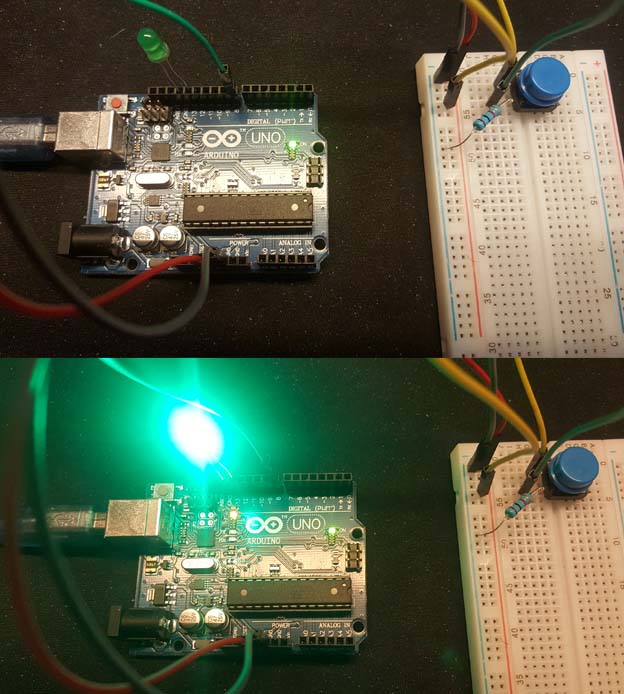
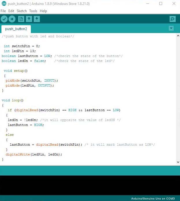
Below is another push button code : when we press the button the LED will turn on and stay on when we unpress the button the LED will turn off and stay off until we press the button again.
In this code I will be using the boolean function which will able me to keep track of the state of the system , it can be true or false / high or low / 0 or 1.
                            /*push button with led and boolean*/

                            int switchPin = 8;
                            int ledPin = 13;
                            boolean lastButton = LOW; /*checkt the state of the button*/
                            boolean ledOn = false; /*check the state of the led*/

                            void setup()
                            {
                            pinMode(switchPin, INPUT);
                            pinMode(ledPin, OUTPUT);
                            }

                            void loop()
                            {
                            if (digitalRead(switchPin) == HIGH && lastButton == LOW)
                            {
                            ledOn = !ledOn; /*it will opposite the value of ledON */
                            lastButton = HIGH;
                            }
                            else
                            {
                            lastButton = digitalRead(switchPin); /* it will mark lastButton as LOW*/
                            }
                            digitalWrite(ledPin, ledOn);
                            }
In the past code the button sometimes works and sometimes it does not: The problem is due to a phenomenon called contact bounce.
For more info aboutSwitch Debouncing
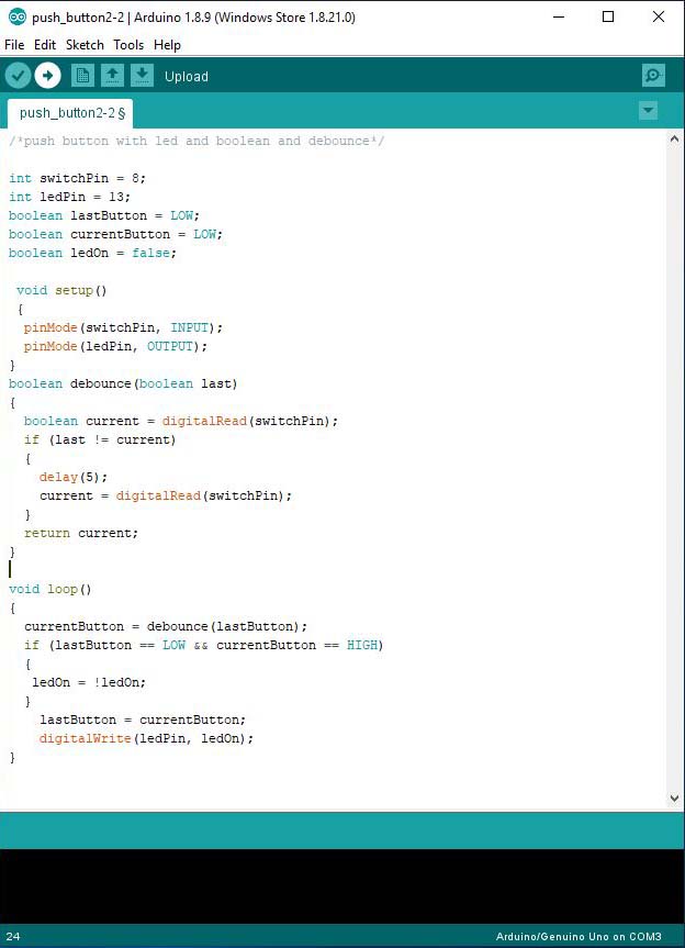
In the code below I will fix that by using the Debounce function.
                            /*push button with led and boolean and debounce*/

                            int switchPin = 8;
                            int ledPin = 13;
                            boolean lastButton = LOW;
                            boolean currentButton = LOW;
                            boolean ledOn = false;


                            void setup()
                            {
                            pinMode(switchPin, INPUT);
                            pinMode(ledPin, OUTPUT);
                            }
                            boolean debounce(boolean last)
                            {
                            boolean current = digitalRead(switchPin);
                            if (last != current)
                            {
                            delay(5);
                            current = digitalRead(switchPin);
                            }
                            return current;
                            }


                            void loop()
                            {
                            currentButton = debounce(lastButton);
                            if (lastButton == LOW && currentButton == HIGH)
                            {
                            ledOn = !ledOn;
                            }
                            lastButton = currentButton;
                            digitalWrite(ledPin, ledOn);
                            }
Push button code 3
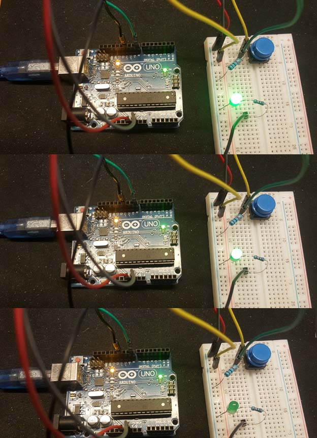
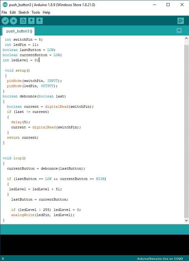
In the code below I will use the push button to change the brightness of the LED, for that I will be using the PWM pin 11 on ARDUINO for the LED:
First I will change the led pin from 13 to pin 11 and instead of the boolean ledON I will be using ledLevel which will be a value from 0 to 255 and below is the new code.
                            int switchPin = 8;
                            int ledPin = 11;
                            boolean lastButton = LOW;
                            boolean currentButton = LOW;
                            int ledLevel = 0;


                            void setup()
                            {
                            pinMode(switchPin, INPUT);
                            pinMode(ledPin, OUTPUT);
                            }
                            boolean debounce(boolean last)
                            {
                            boolean current = digitalRead(switchPin);
                            if (last != current)
                            {
                            delay(5);
                            current = digitalRead(switchPin);
                            }
                            return current;
                            }


                            void loop()
                            {
                            currentButton = debounce(lastButton);

                            if (lastButton == LOW && currentButton == HIGH)
                            {
                            ledLevel = ledLevel + 51;
                            }
                            lastButton = currentButton;

                            if (ledLevel > 255) ledLevel = 0;
                            analogWrite(ledPin, ledLevel);
                            }
In summary the push button needs 1 digital input pin and in the programming I can make it do different scenario.
2-LDR sensor
A photoresistor (or light-dependent resistor, LDR, or photo-conductive cell) is a light-controlled variable resistor. The resistance of a photoresistor decreases with increasing incident light intensity
LDR Code 1
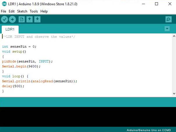
In the code below I will use an LDR and monitor the value using serial print function.
                            /*LDR INPUT and observe the values*/

                            int sensePin = 0;
                            void setup()
                            {
                            pinMode(sensePin, INPUT);
                            Serial.begin(9600);
                            }
                            void loop() {
                            Serial.println(analogRead(sensePin));
                            delay(500);
                            }
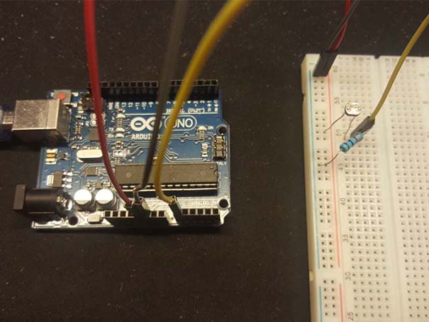
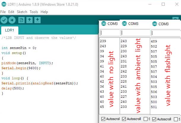
I will go now to tools and click on Serial Monitor to read the values of the LDR.
LDR Code 2
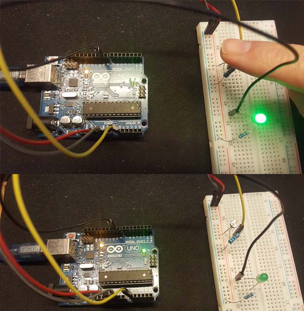
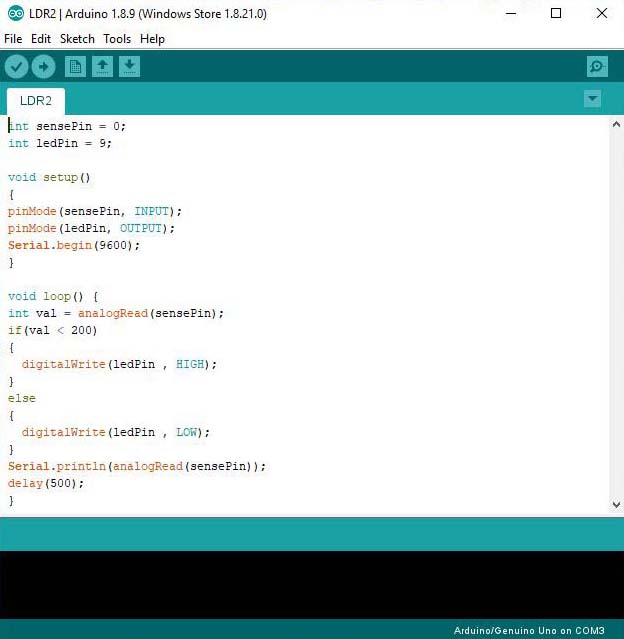
Now I will add a LED and make it light only if the LDR sensor value is below 200.
                            int sensePin = 0;
                            int ledPin = 9;

                            void setup()
                            {
                            pinMode(sensePin, INPUT);
                            pinMode(ledPin, OUTPUT);
                            Serial.begin(9600);
                            }

                            void loop() {
                            int val = analogRead(sensePin);
                            if(val < 200) { digitalWrite(ledPin , HIGH); } else { digitalWrite(ledPin , LOW); } Serial.println(analogRead(sensePin)); delay(500); }
LDR Code 3
Now I will make the brightness of the LED depending on the LDR value.
For this I will be using the Constraint function to limit the value of the LDR between 50 and 400 and then use the map function to transform the LDR value from 50 to 0 and 400 to 255 respectively. And will use this value as an intensity value (analogWrite) for the LED
                            int sensePin = 0;
                            int ledPin = 9;

                            void setup()
                            {
                            // put your setup code here, to run once:
                            pinMode(sensePin, INPUT);
                            pinMode(ledPin, OUTPUT);
                            Serial.begin(9600);
                            }

                            void loop() {
                            int val = analogRead(sensePin);
                            val = constrain(val, 50, 400);
                            int ledLevel = map(val, 50, 400, 0, 255);

                            analogWrite(ledPin , ledLevel);
                            Serial.println(analogRead(sensePin));
                            delay(500);
                            }
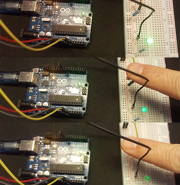
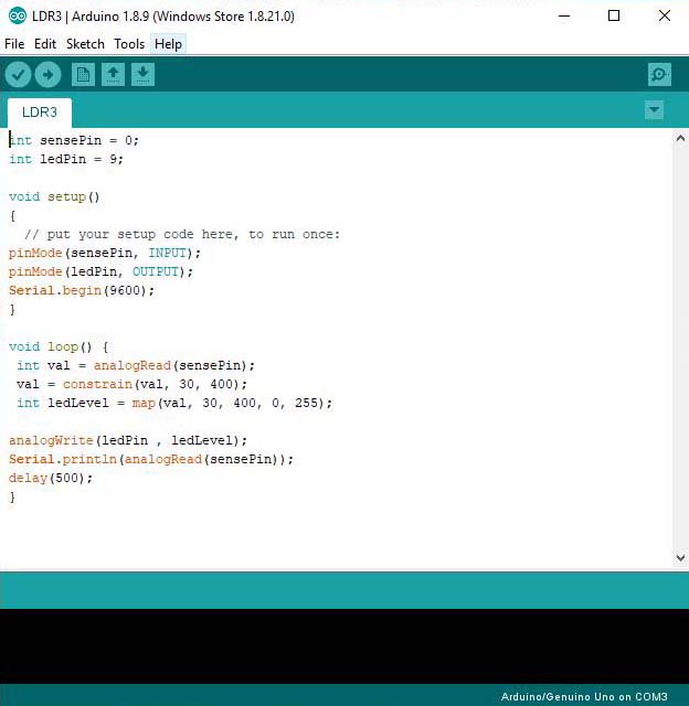
In summary the LDR sensor needs 1 analog input pin to read the changing values.
3-Water level sensor
It is the same concept of a push button but instead of connecting the wires to the push button they will be placed in a water tank, one on the low level and the other on the high level. When the water arrives to the high level the LED will turn on.
In the testing below I used a potentiometer to detect the low signal connecting the two wires through the water.
                            /*water level detection */

                            int wl = 4;
                            int ledPin = 12;

                            void setup()
                            {
                            pinMode(wl, INPUT);
                            pinMode(ledPin, OUTPUT);
                            }

                            void loop()
                            {
                            if (digitalRead(wl) == HIGH)
                            {
                            digitalWrite(ledPin, HIGH);
                            delay(100);
                            }
                            else
                            {
                            digitalWrite(ledPin, LOW);
                            delay(100);
                            }

                            }
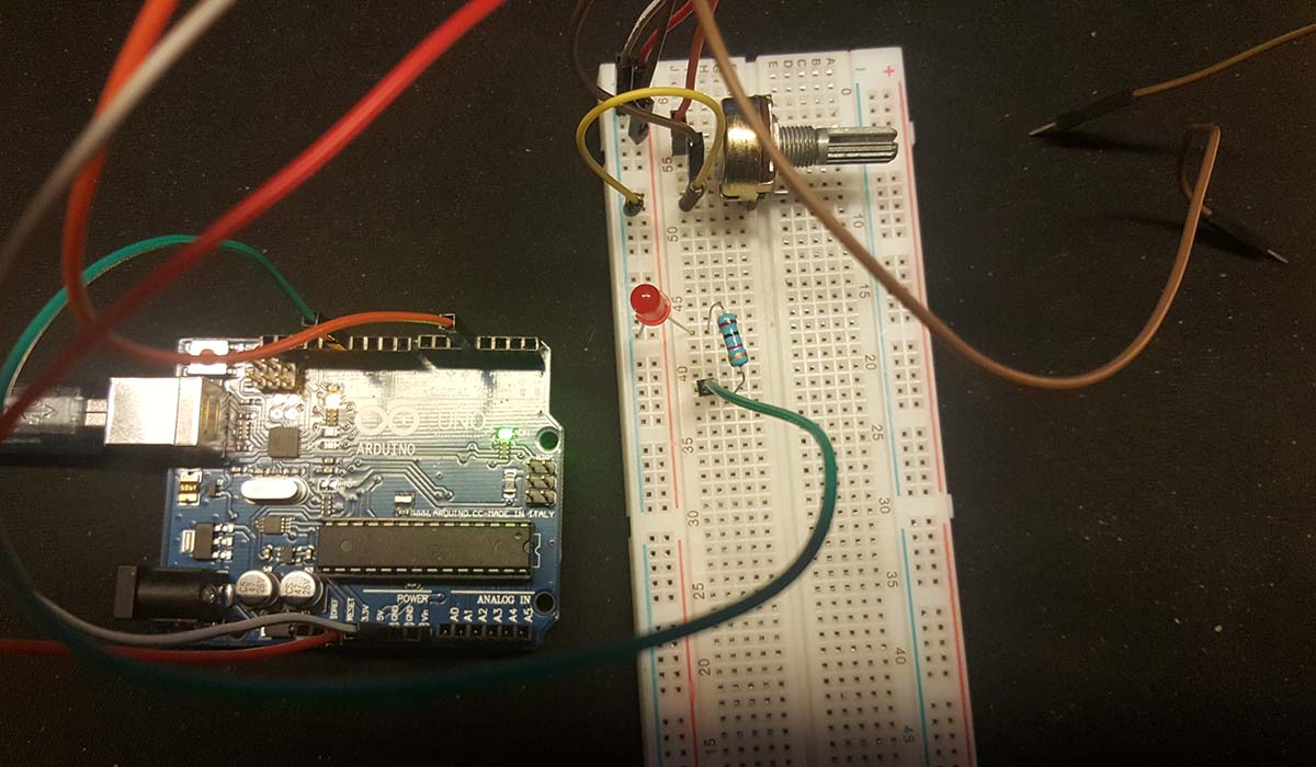
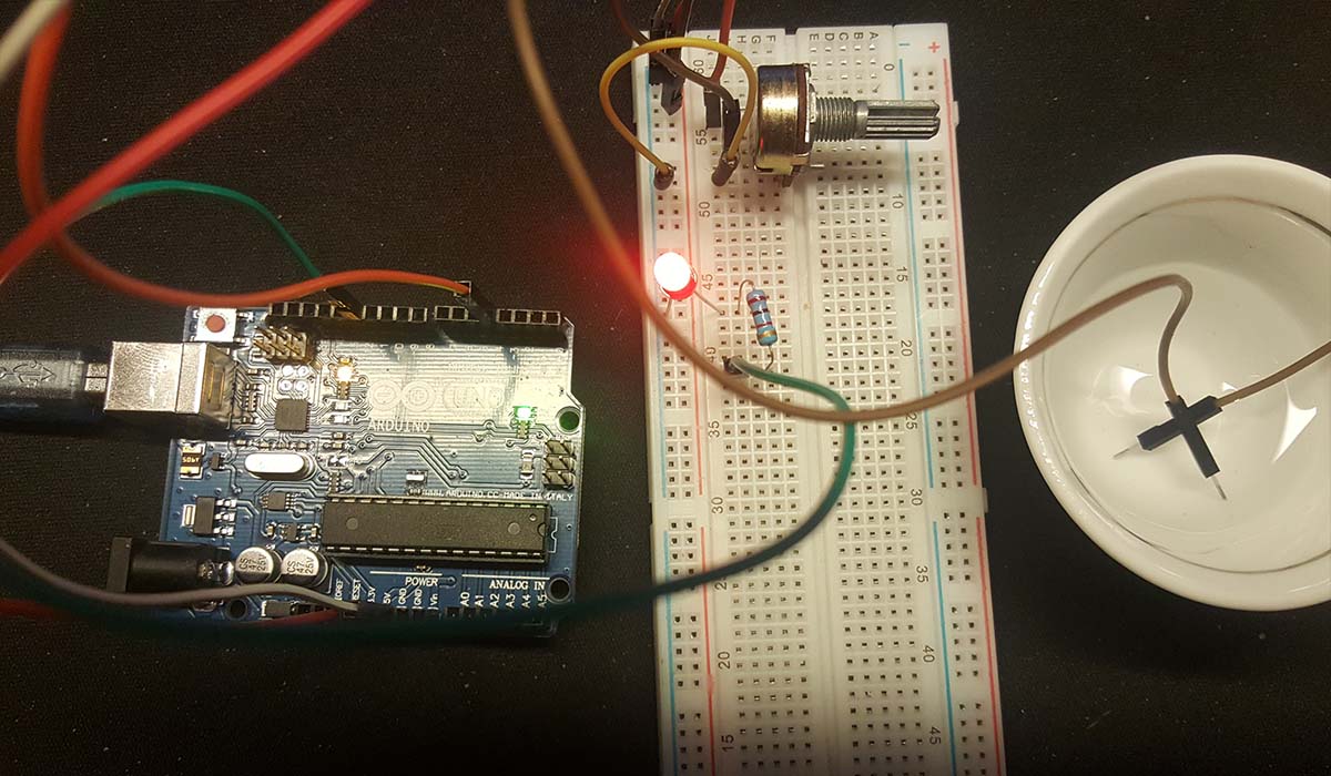
In summary the water level detection needs 1 digital input pin for each water level I want to detect.
4-Soil moisture sensor
A soil moisture sensor will detect the water quantity in the soil. Below are the connection and the code
                            /* Soil Mositure Basic Example
                            This sketch was written by SparkFun Electronics
                            Joel Bartlett
                            August 31, 2015

                            Basic skecth to print out soil moisture values to the Serial Monitor

                            Released under the MIT License(http://opensource.org/licenses/MIT)
                            */

                            int val = 0; //value for storing moisture value
                            int soilPin = A0;//Declare a variable for the soil moisture sensor
                            int soilPower = 7;//Variable for Soil moisture Power

                            //Rather than powering the sensor through the 3.3V or 5V pins,
                            //we'll use a digital pin to power the sensor. This will
                            //prevent corrosion of the sensor as it sits in the soil.

                            void setup()
                            {
                            Serial.begin(9600); // open serial over USB

                            pinMode(soilPower, OUTPUT);//Set D7 as an OUTPUT
                            digitalWrite(soilPower, LOW);//Set to LOW so no power is flowing through the sensor
                            }

                            void loop()
                            {
                            Serial.print("Soil Moisture = ");
                            //get soil moisture value from the function below and print it
                            Serial.println(readSoil());

                            //This 1 second timeframe is used so you can test the sensor and see it change in real-time.
                            //For in-plant applications, you will want to take readings much less frequently.
                            delay(1000);//take a reading every second
                            }
                            //This is a function used to get the soil moisture content
                            int readSoil()
                            {

                            digitalWrite(soilPower, HIGH);//turn D7 "On"
                            delay(10);//wait 10 milliseconds
                            val = analogRead(soilPin);//Read the SIG value from sensor
                            digitalWrite(soilPower, LOW);//turn D7 "Off"
                            return val;//send current moisture value
                            }
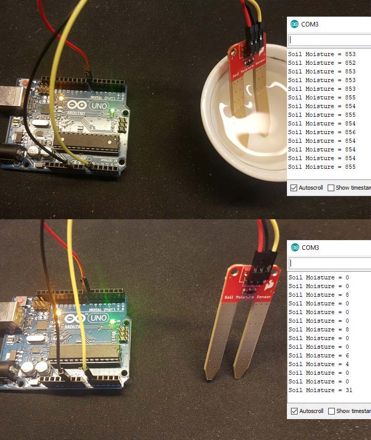
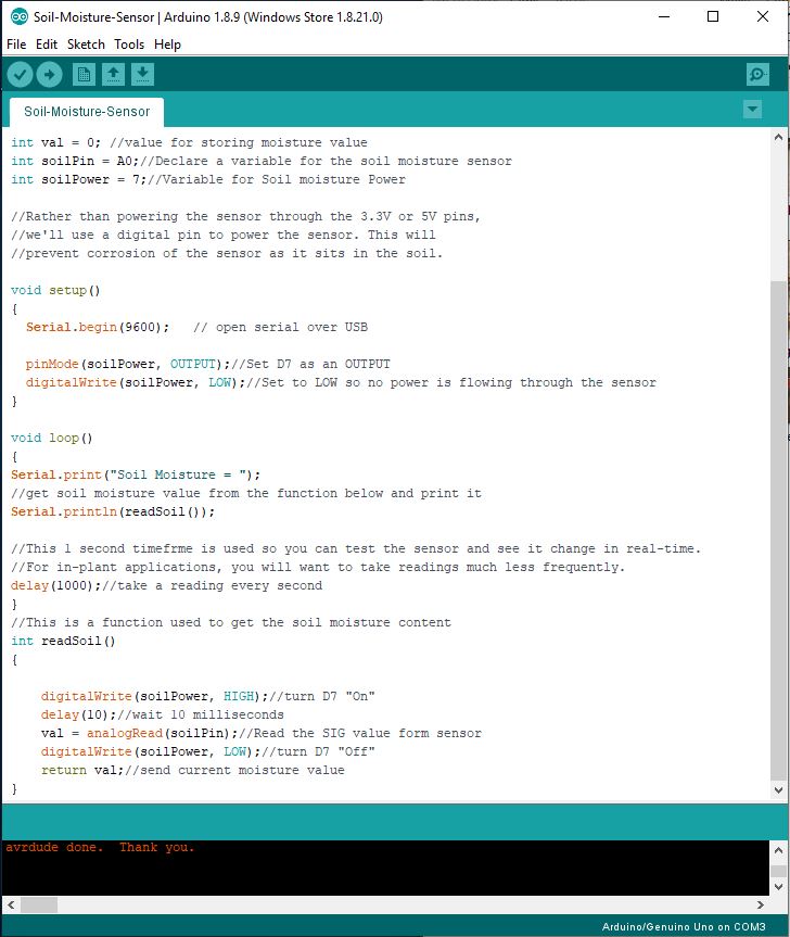
In summary the soil moisture sensor needs only 1 analog input pin to read the changing values but if we need to power it only when reading the value than we have to use 1 digital ouput also (as per the example above to avoid constant power on the sensor and prevent its corrosion as it sits in the soil ).
5-DHT22 temperature and a humidity sensor
DHT22 is a temperature and a humidity sensor. Below are the connection and the code.
                            /* How to use the DHT-22 sensor with Arduino uno
                            Temperature and humidity sensor
                            More info: http://www.ardumotive.com/how-to-use-dht-22-sensor-en.html
                            Dev: Michalis Vasilakis // Date: 1/7/2015 // www.ardumotive.com */

                            //Libraries
                            #include
                                dht DHT;
                                //Constants
                                #define DHT22_PIN 2 // DHT 22 (AM2302) - what pin we're connected to

                                //Variables
                                float hum; //Stores humidity value
                                float temp; //Stores temperature value

                                void setup()
                                {
                                Serial.begin(9600);
                                }

                                void loop()
                                {
                                int chk = DHT.read22(DHT22_PIN);
                                //Read data and store it to variables hum and temp
                                hum = DHT.humidity;
                                temp= DHT.temperature;
                                //Print temp and humidity values to serial monitor
                                Serial.print("Humidity: ");
                                Serial.print(hum);
                                Serial.print(" %, Temp: ");
                                Serial.print(temp);
                                Serial.println(" Celsius");
                                delay(2000); //Delay 2 sec.
                                }
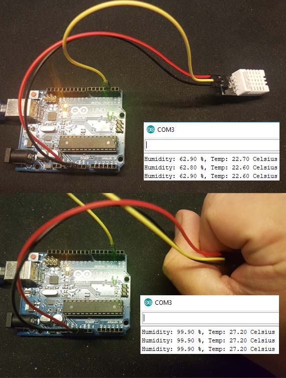
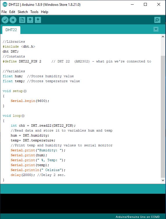
In summary the DHT22 sensor needs only 1 digital input pin to read the changing values .
6-Clock module
The MH-Real-Time Clock Module DS1302 will enable me to monitor the date and time. Below are the connection and the code.
                            //This code is to use with DS1302 RTC module, it permits you to setup the actual time and date
                            //And you can visualize them on the serial monitor
                            //This code is a modified version of the code provided in virtuabotixRTC library
                            //Refer to Surtrtech Youtube channel/Facebook page for more information


                            #include  //Library used


                                //Wiring SCLK -> 6, I/O -> 7, CE -> 8
                                //Or CLK -> 6 , DAT -> 7, Reset -> 8

                                virtuabotixRTC myRTC(6, 7, 8); //If you change the wiring change the pins here also

                                void setup() {
                                Serial.begin(9600);

                                // Set the current date, and time in the following format:
                                // seconds, minutes, hours, day of the week, day of the month, month, year
                                myRTC.setDS1302Time(15, 36, 18, 7, 31, 3, 2019); //Here you write your actual time/date as shown above
                                //but remember to "comment/remove" this function once you're done
                                //The setup is done only one time and the module will continue counting it automatically
                                }

                                void loop() {
                                // This allows for the update of variables for time or accessing the individual elements.
                                myRTC.updateTime();

                                // Start printing elements as individuals
                                Serial.print("Current Date / Time: ");
                                Serial.print(myRTC.dayofmonth); //You can switch between day and month if you're using American system
                                Serial.print("/");
                                Serial.print(myRTC.month);
                                Serial.print("/");
                                Serial.print(myRTC.year);
                                Serial.print(" ");
                                Serial.print(myRTC.hours);
                                Serial.print(":");
                                Serial.print(myRTC.minutes);
                                Serial.print(":");
                                Serial.println(myRTC.seconds);

                                // Delay so the program doesn't print non-stop
                                delay(1000);
                                }
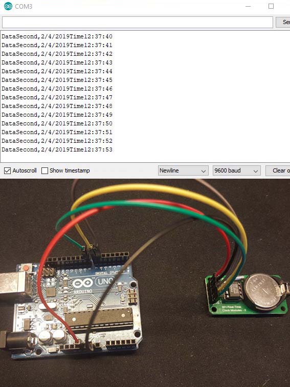
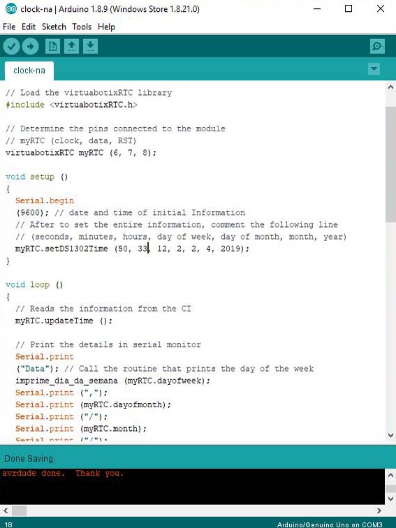
In summary the clock module needs 3 digital input pin to read the changing values: Pin D6, D7 and D8.
INPUTS / OUTPUTS
Based on the testing above, I designed and produced my Board on week 12 "Output Device" where I connected all my input / output sensors and tested my code.
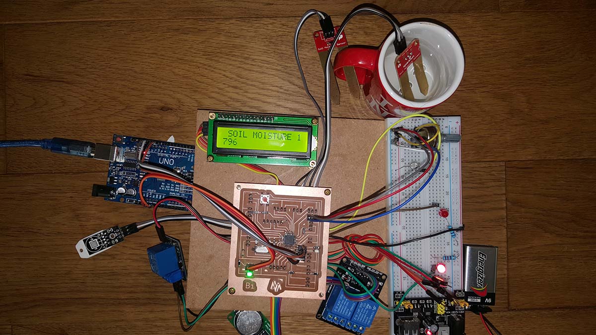
Below is my final sketch.
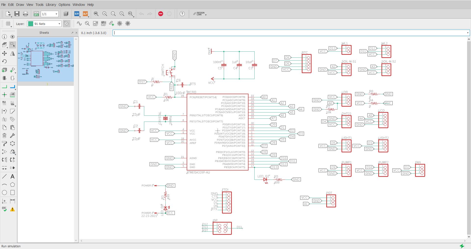
And it will include the following components with their relative Pins:
- The Reset button
- The power Pinhead with a LED and the board capacitors
- The Crystal 16Mhz with the capacitors
- The FTDI connection
- The ISP connection
- A connection for an LDR on Pin A0
- A connection for an potentiometer on Pin A1
- A connection for a Soil moitsure sensor1 and Soil moisture sensor2 on Pin A2 and A3.
- A connection for a Liquid Crystal Display LCD on Pin A4 and A5.
- A connection for a Relay on Pin D2 for a FAN
- A connection for a Relay on Pin D3 for a Light
- A connection for a Temperature and Humidity Sensor DHT22 on Pin D4
- A connection for a Relay on Pin D5 for a Grow Light
- A connection for a Real Time Clock module on Pin D6, D7 and D8
- A connection for a Relay on Pin D9 for a Drainage pump
- A connection for a Relay on Pin D10 for a watering pump
- A connection for water level Sensor on Pin D11
- A connection for water level Sensor on Pin D12
- A connection for water level Sensor on Pin D13
And below is my board design
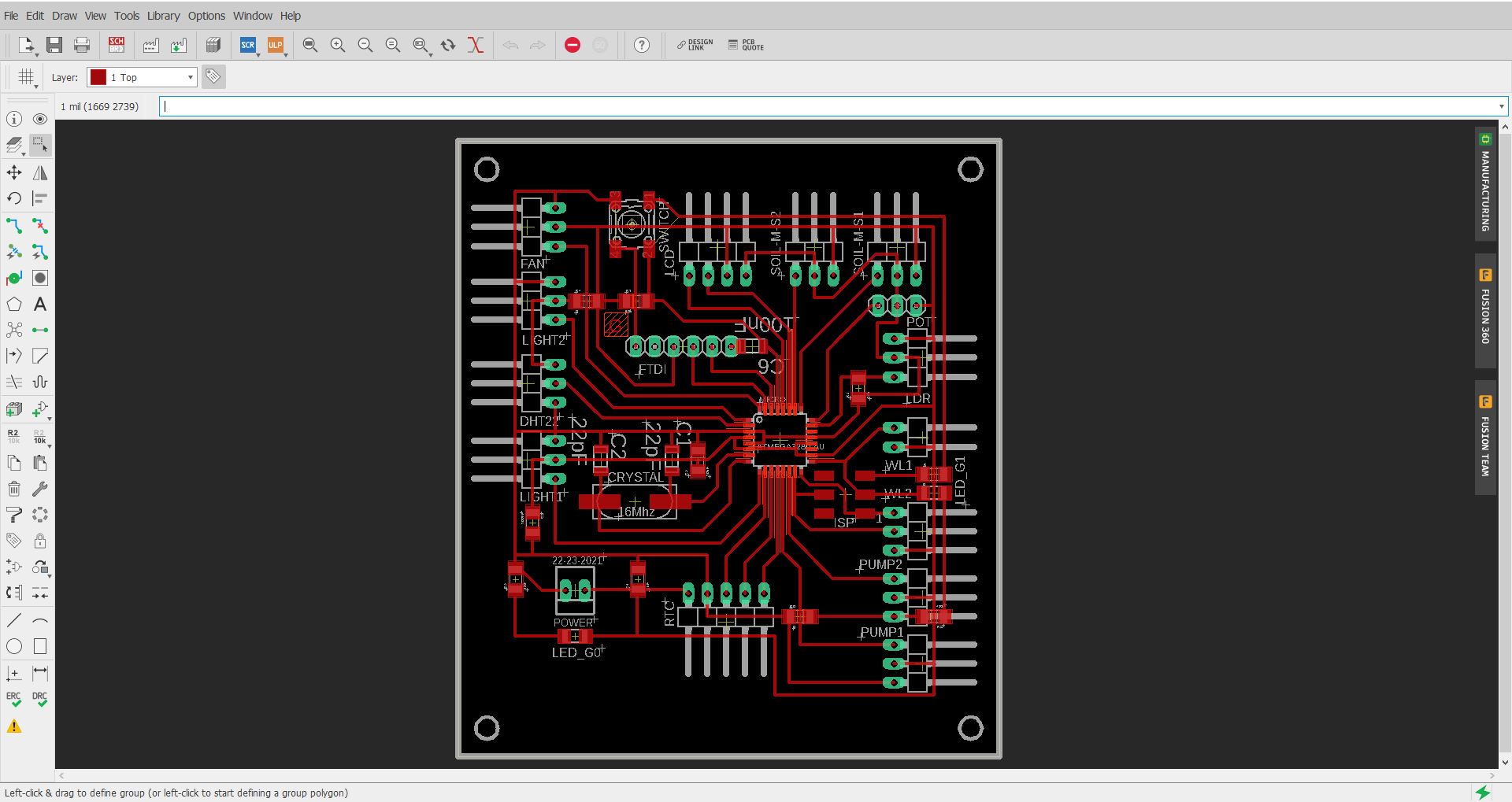
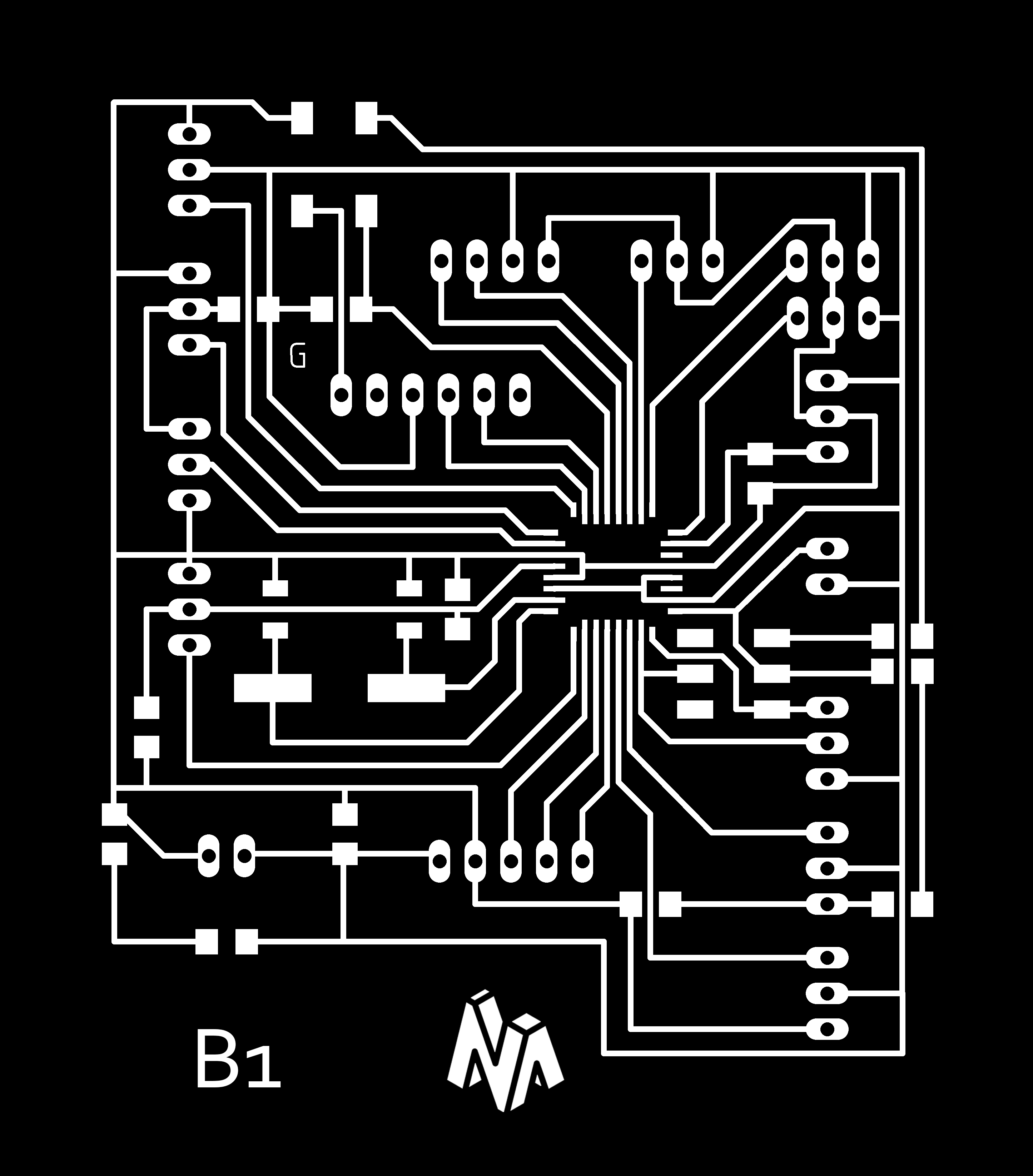
After that, I exported the inner traces image , the drilling image and the cuting image.


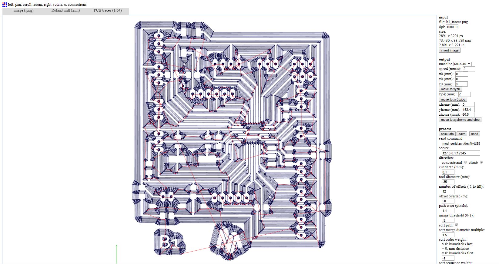
And below is the g-code for the inner traces
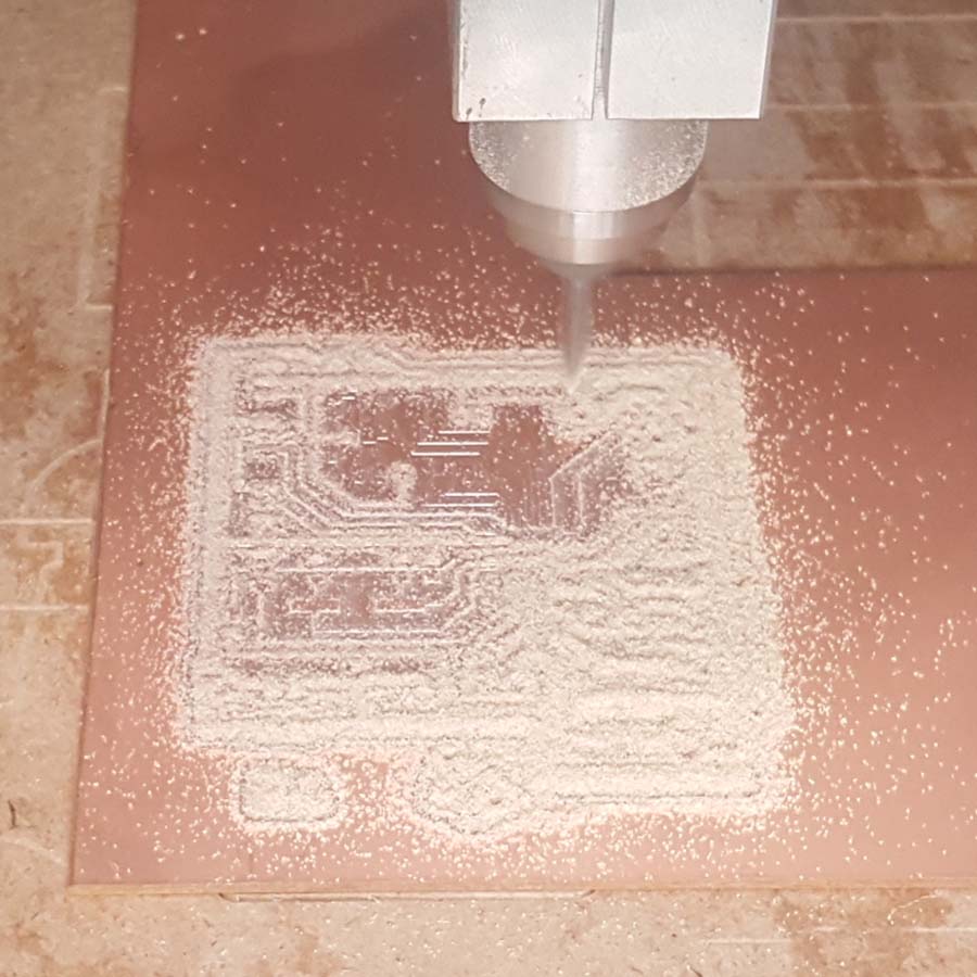
Milling the board and soldering the components
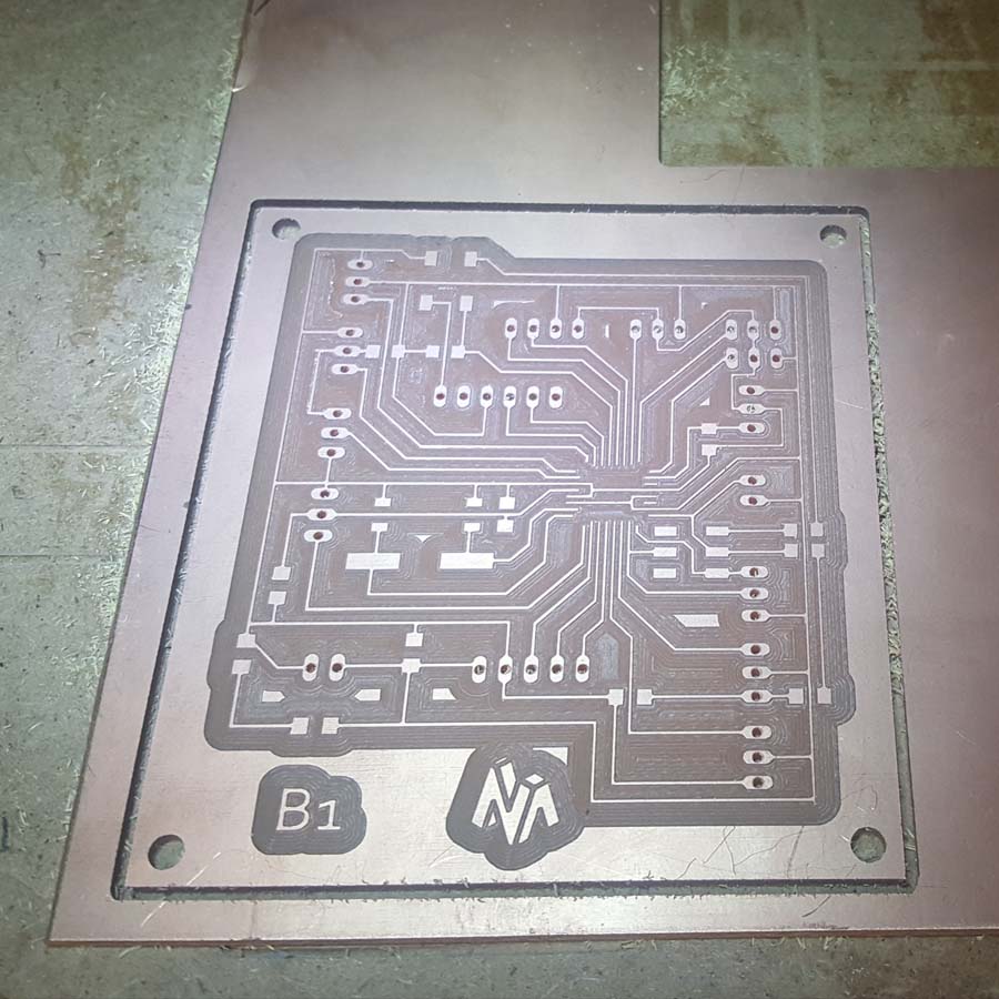
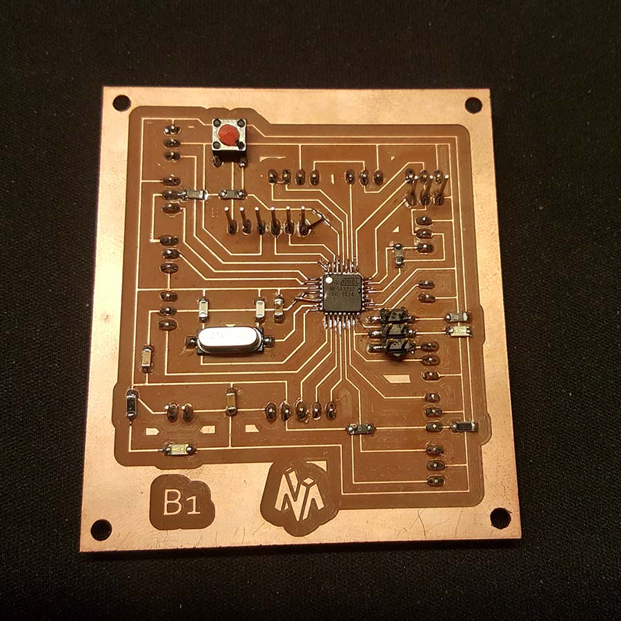
Below is the code used for testing:
                            /*Impport following Libraries*/
                            #include
                                #include
                                    LiquidCrystal_I2C lcd(0x3f, 2, 1, 0, 4, 5, 6, 7, 3, POSITIVE); //I2C pins declaration
                                    // Load the virtuabotixRTC library
                                    #include
                                        // myRTC (clock, data, RST)
                                        virtuabotixRTC myRTC (6, 7, 8);// Determine the pins connected to the module
                                        //Load the DHT library
                                        #include
                                            dht DHT;
                                            #define DHT22_PIN 4 // DHT 22 (AM2302) - what pin we're connected to

                                            //Variables
                                            float hum; //Stores humidity value
                                            float temp; //Stores temperature value


                                            int sensePin = 0;/*Declare a variable for the lDR */
                                            int potPin = A1;/*Declare a variable for the Potentiometer */
                                            int soilPin1 = A2;/*Declare a variable for the soil moisture sensor 1 */
                                            int soilPin2 = A3;/*Declare a variable for the soil moisture sensor 2 */
                                            int waterLev1 = 11;/*Declare a variable for the water level 1(for pot1) */
                                            int waterLev2 = 12;/*Declare a variable for the water level 2 (for pot2) */
                                            int waterLev3 = 13;/*Declare a variable for the water level 3 (for water tank) */
                                            int relayPinF = 2;/*Declare a variable for the relay / FAN */
                                            int relayPinL1 = 5;/*Declare a variable for the relay / LIGHT1 */
                                            int relayPinL2 = 3;/*Declare a variable for the relay / LIGHT2 */
                                            int relayPinP1 = 9;/*Declare a variable for the relay / PUMP1 */
                                            int relayPinP2 = 10;/*Declare a variable for the relay / PUMP2 */


                                            void setup()

                                            {
                                            // put your setup code here, to run once:
                                            pinMode(sensePin, INPUT);
                                            pinMode(potPin, INPUT);
                                            pinMode(soilPin1, INPUT);
                                            pinMode(soilPin2, INPUT);
                                            pinMode(waterLev1, INPUT);
                                            pinMode(waterLev2, INPUT);
                                            pinMode(waterLev3, INPUT);

                                            pinMode(relayPinF, OUTPUT);
                                            pinMode(relayPinL1, OUTPUT);
                                            pinMode(relayPinL2, OUTPUT);
                                            pinMode(relayPinP1, OUTPUT);
                                            pinMode(relayPinP2, OUTPUT);
                                            Serial.begin(9600);

                                            lcd.begin(16, 2); //Defining 16 columns and 2 rows of lcd display
                                            lcd.backlight();//To Power ON the back light
                                            //lcd.backlight();// To Power OFF the back light

                                            // After to set the entire information, comment the following line
                                            // (seconds, minutes, hours, day of week, day of month, month, year)
                                            myRTC.setDS1302Time (50, 13, 11, 2, 9, 4, 2019);
                                            }

                                            void loop()
                                            {
                                            /*Reads the information from the CI */
                                            myRTC.updateTime ();

                                            /*dht control */
                                            int chk = DHT.read22(DHT22_PIN);//Read data and store it to variables hum and temp
                                            hum = DHT.humidity;
                                            temp = DHT.temperature;

                                            /*LCD control */
                                            lcd.clear();//Clean the screen
                                            lcd.setCursor(2, 0); //Defining position to write from first row,first column .
                                            lcd.print("LDR VALUE "); //You can write 16 Characters per line .
                                            delay(200);//Delay used to give a dynamic effect
                                            lcd.setCursor(0, 1); //Defining position to write from second row,first column .
                                            lcd.print(analogRead(sensePin));
                                            delay(1000);

                                            lcd.clear();//Clean the screen
                                            lcd.setCursor(0, 0);
                                            lcd.print(" TEMP ");
                                            lcd.setCursor(0, 1);
                                            lcd.print(temp);
                                            delay(1000);

                                            lcd.clear();//Clean the screen
                                            lcd.setCursor(0, 0);
                                            lcd.print(" HUMIDITY ");
                                            lcd.setCursor(0, 1);
                                            lcd.print(hum);
                                            delay(1000);

                                            lcd.clear();//Clean the screen
                                            lcd.setCursor(0, 0);
                                            lcd.print(" SOIL MOISTURE 1 ");
                                            lcd.setCursor(0, 1);
                                            lcd.print(analogRead(soilPin1));
                                            delay(1000);

                                            lcd.clear();//Clean the screen
                                            lcd.setCursor(0, 0);
                                            lcd.print(" SOIL MOISTURE 2 ");
                                            lcd.setCursor(0, 1);
                                            lcd.print(analogRead(soilPin2));
                                            delay(1000);

                                            lcd.clear();//Clean the screen
                                            lcd.setCursor(0, 0);
                                            lcd.print(" TIME ");
                                            lcd.setCursor(0, 1);
                                            lcd.print(myRTC.hours);
                                            lcd.setCursor(2, 1);
                                            lcd.print(":");
                                            lcd.setCursor(3, 1);
                                            lcd.print(myRTC.minutes);
                                            delay(1000);

                                            /*relay control L1 */
                                            int val = analogRead(sensePin);
                                            if (val < 500) digitalWrite(relayPinL1 , HIGH); } else { digitalWrite(relayPinL1 , LOW); } }
Testing the code
The breadboard is only being used to power the main board and the supply power for the components attached to the relay and it is just for testing purpose.
Group assignment
Analog Read
In this group assignment we are going to read an analog input on the Tektronix TBS1052B Digital Oscilloscope. For that we used my hello board from Week7 Electronic Design on which I have an LDR.
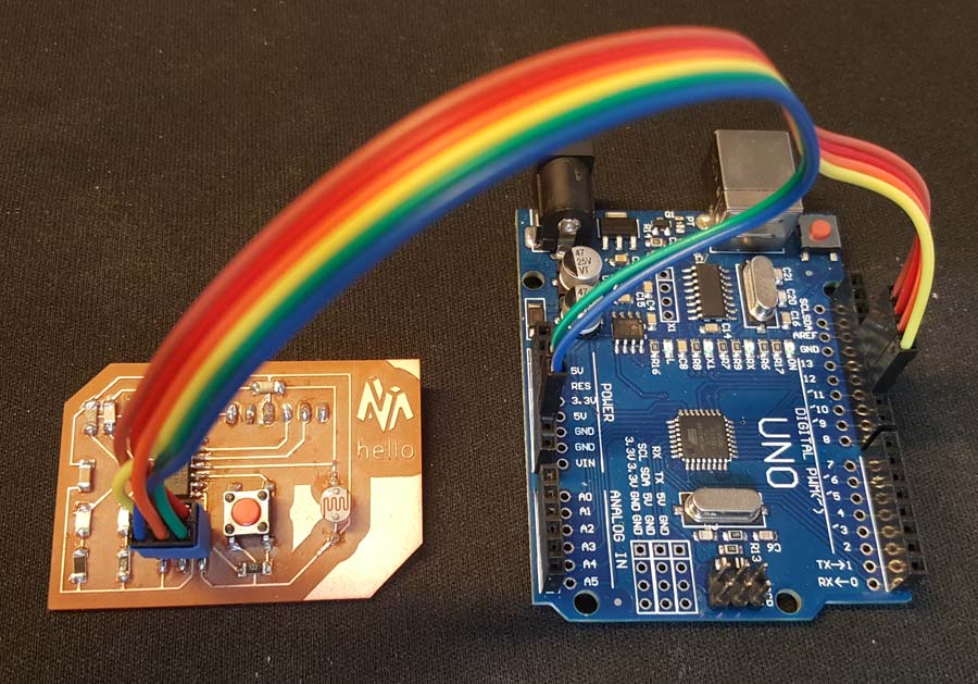
Below is the code used; When I push the Button; If there is light than the Green led should turn on, if not the Red led should turn on
                                // constants won't change. Used here to set a pin number:
                                const int buttonPin = 3;//the number of the pushbutton pin
                                const int ldrPin = A2;//the number of LDR pin
                                const int ledPingreen = 8;// the number of the greenLED pin
                                const int ledPinred = 7;// the number of the redLED pin

                                // Variables will change:
                                int ledState = LOW; // ledState used to set the LED

                                int buttonState = 0;
                                int sensorValue = 0; // variable to store the value coming from the sensor

                                int value = 0;

                                void setup()
                                {
                                // put your setup code here, to run once:
                                // set the digital pin as output:
                                pinMode(ledPingreen, OUTPUT);
                                pinMode(ledPinred, OUTPUT);

                                // set the digital pin as input:
                                pinMode(buttonPin, INPUT);
                                pinMode(ldrPin, INPUT);

                                }

                                void loop()
                                {
                                // read the state of the pushbutton value:
                                buttonState = digitalRead(buttonPin);

                                // check if the pushbutton is pressed. If it is, the buttonState is HIGH:
                                if (buttonState == HIGH)
                                {
                                // read the value from the sensor:
                                sensorValue = analogRead(ldrPin);
                                value = map(sensorValue,0,1023,0,100);
                                if ( value>50)
                                {
                                // put your main code here, to run repeatedly:
                                digitalWrite(ledPingreen, HIGH); // turn the LED on (HIGH is the voltage level)
                                digitalWrite(ledPinred, LOW); // turn the LED on (HIGH is the voltage level)
                                delay(1000);
                                }
                                else
                                {
                                // put your main code here, to run repeatedly:
                                digitalWrite(ledPingreen, LOW); // turn the LED on (HIGH is the voltage level)
                                digitalWrite(ledPinred, HIGH); // turn the LED on (HIGH is the voltage level)
                                delay(1000);
                                }
                                }
                                else
                                {
                                digitalWrite(ledPingreen, LOW); // turn the LED off by making the voltage LOW
                                digitalWrite(ledPinred, LOW); // turn the LED off by making the voltage LOW
                                }
                                // wait for a second

                                }
We connected the Positive probe to the LDR and the Negative Probe the GND. Below we can see the values changing on the Oscilloscope screen depending on the light intensity.
Digital Read
Now we will read the Digital signal of an Ultra Sonic Sensor ; for that we connected an ultrasonic sensor to Arduino read two signal on the Oscilloscope.
Files
Click Here to download the Push Button code
Click Here to download the LDR sensor code
Click Here to download the Water level code
Click Here to download the Soil moisture sensor code
Click Here to download the temperature and a humidity sensor code
Click Here to download the Clock module code
Click Here to download the eagle file
Click Here to download the board traces
Click Here to download the board drills
Click Here to download the board cutout
