Assignment
individual assignment:
write an application that interfaces with an input &/or output device
that you made
group assignment:
compare as many tool options as possible
Individual assignment
Processing
Below are some references
- What is Processing ? Wikipedia
- Processing Website
- Processing Tutorial
- Connecting-arduino-to-processing Sparkfun
- Processing References
- Processing Tutorial Daniel Shiffmen
Sketch 1
Based on the Sparkfun tutorial I have tested the connection between Processing and Arduino
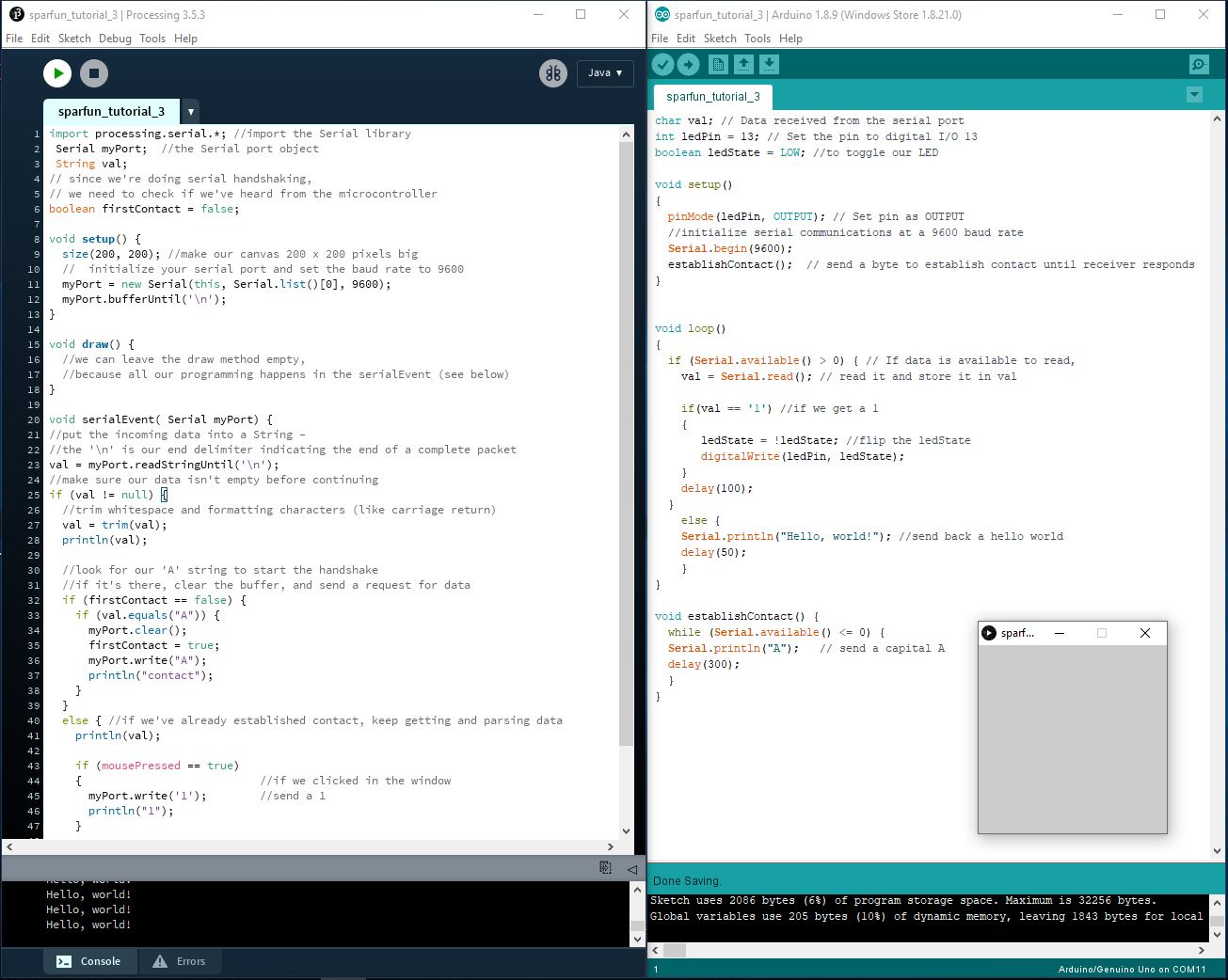
When I press the mouse button inside the processing box ,the led on my board will turn on and when I press again it will turn off
Sketch 2
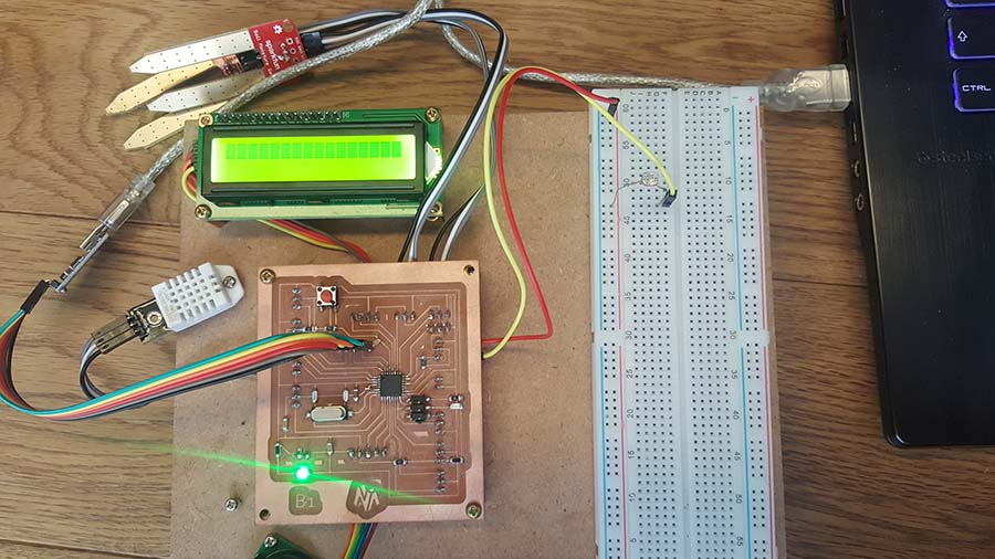
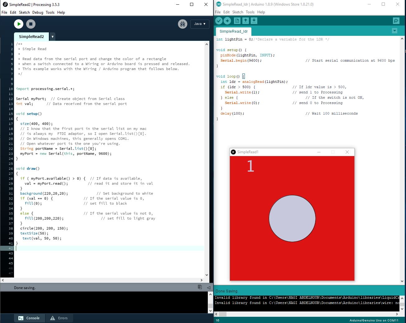
Now I will test a simple serial connection with the ldr value of my previous Board B1
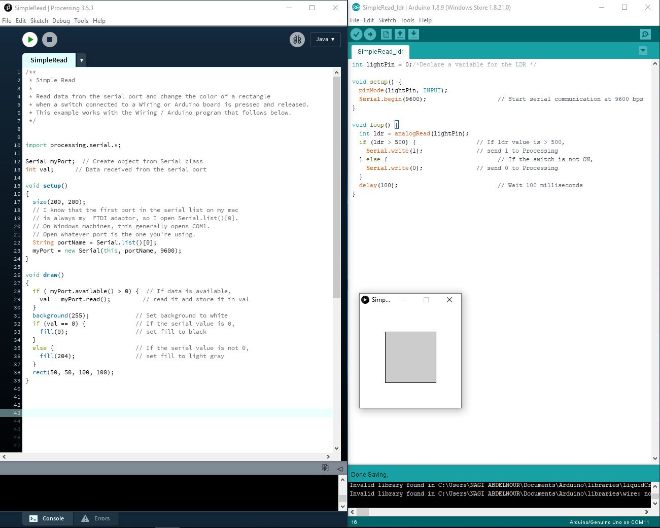
Code explanation:
In Arduino code the ldr value is checked , if the value is higher than 500 than it will send 1 on the serial if not it will send 0
In Processing software the code reads the value received on the serial and if it is equal to 0 than it will draw a rectangle with black color "fill (0)" if else it will change the color to grey "fill (204)"
After that I have made some adjustments in the code and changed the size of the display from 200x200 to 400x400 and change the rectangle to circle.
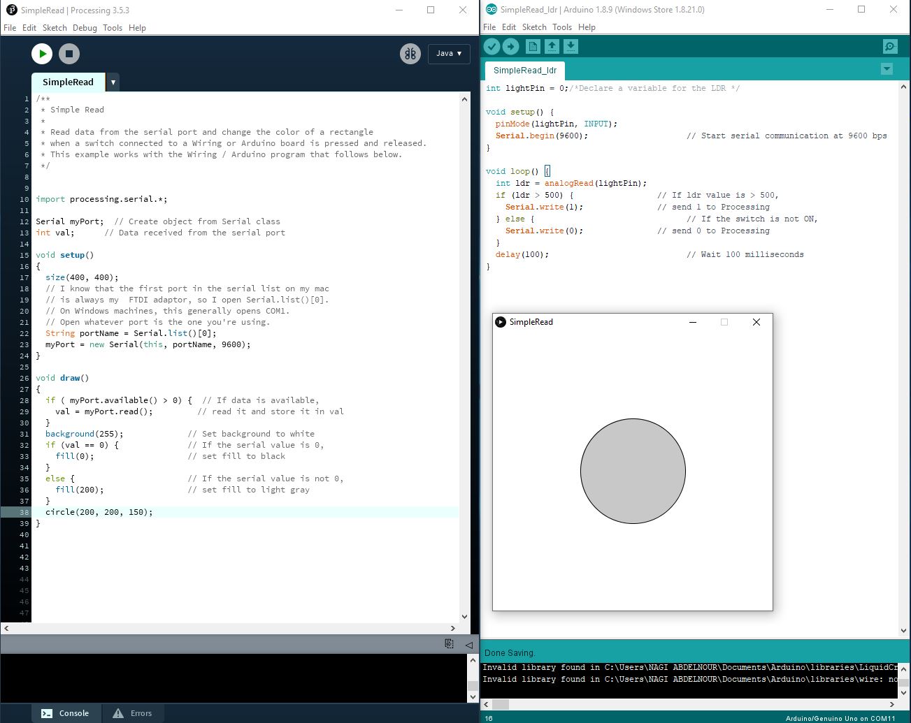
After that I have changed the background color and added a text showing the received values

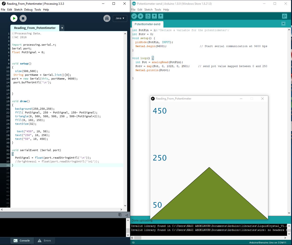
Sketch 3
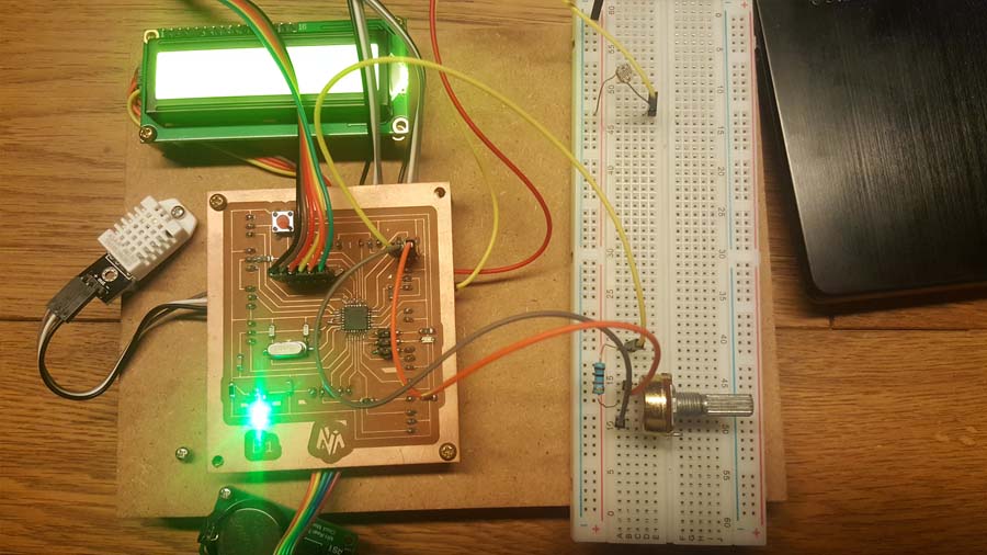
Now I will test another simple serial connection with a Potentiometer connected to my Board B1
Sketch 4
Now I will control the Led on Pin13 with the Potentiometer connected to my Board B1
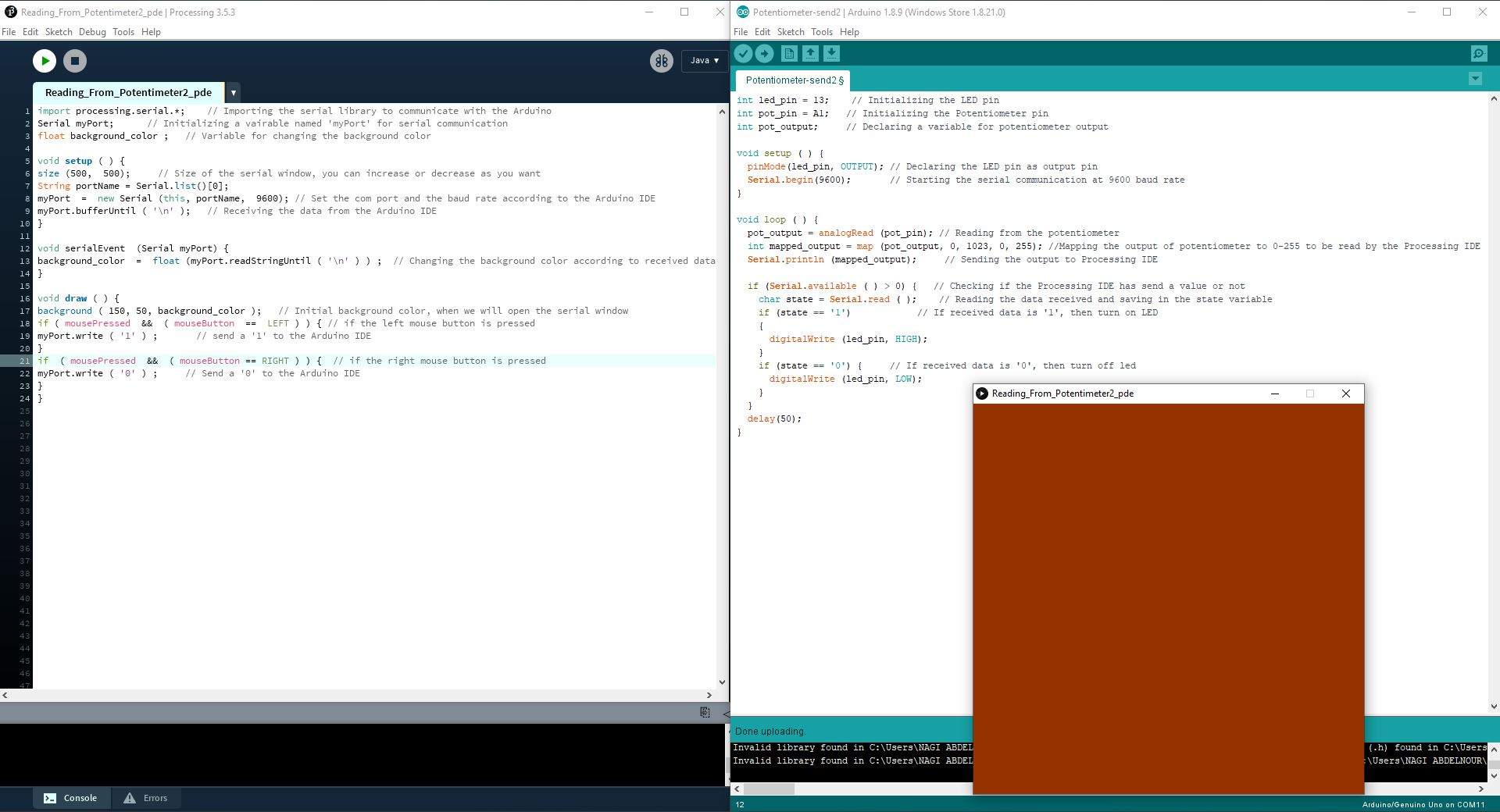
The background color will change with the potentiometer value and the led is controlled by the mouse buttons: left click will turn on the led and the right-click will turn off the led.
Group Assignment:
Compare as many tool options as possible
Check Berytech page for the Group Assignment
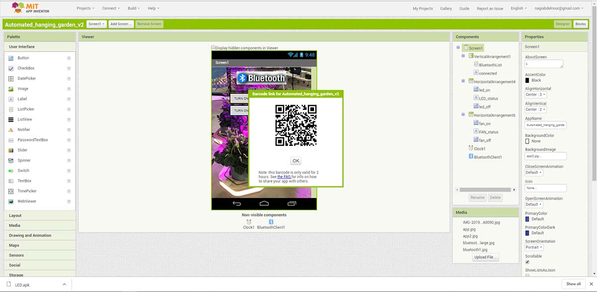
As from my side I tried the MIT APP INVENTOR
I will connect through bluetooth to turn on and off the led light and the fan of my final project
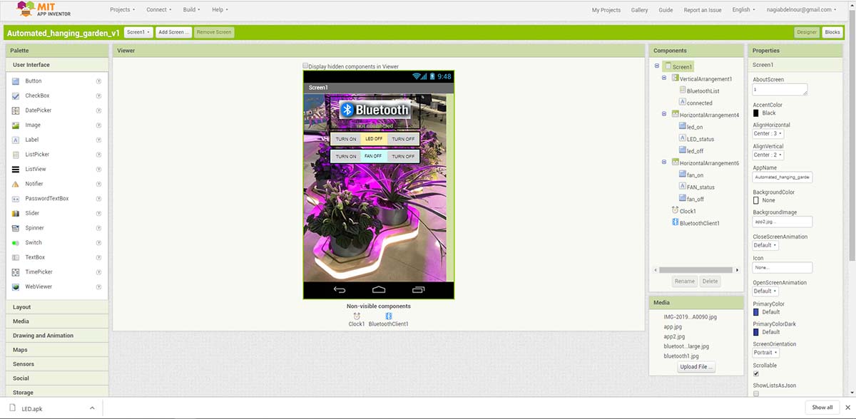
To turn on the led it will send 1 via the appliction and to turn off the led it will send 0
To turn on the fan it will send A via the appliction and to turn off the fan it will send B
After that I will press on build to generate the application.
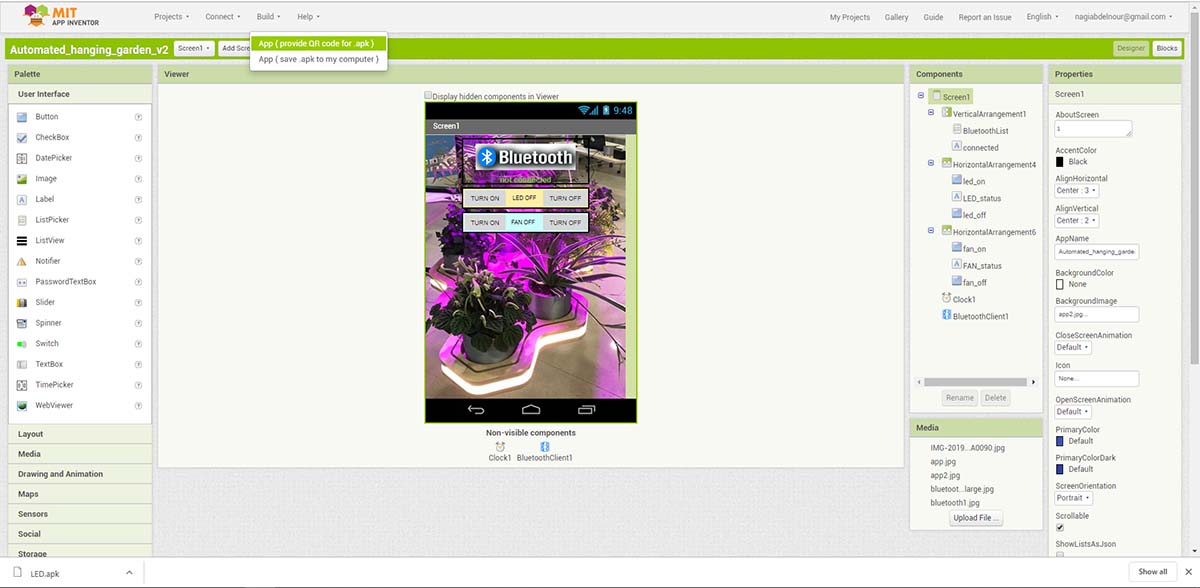
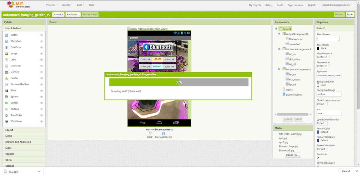
I will receive a QRCODE to read via my phone to install the application.
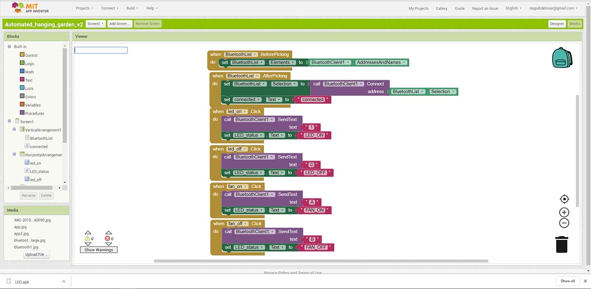
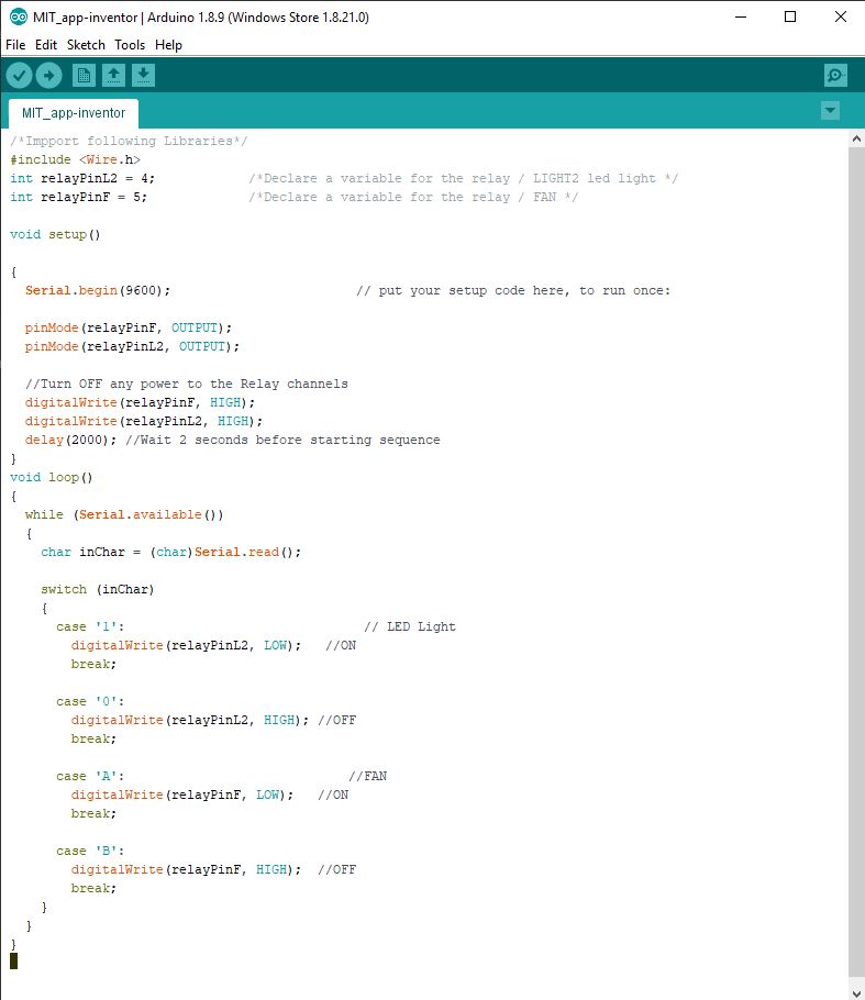
And this is the code used for testing
Files
Click Here to download the Processing Sketch 2
Click Here to download the Arduino Sketch 2
Click Here to download the Processing Sketch 3
Click Here to download the Arduino Sketch 3
Click Here to download the Processing Sketch 4
Click Here to download the Arduino Sketch 4
Click Here to download the mit-app-inventor Bluetooth Code
Click Here to download the Phone App