11. Output Devices
• Group assignment: Measure the power consumption of an output device.
• Individual assignment: Add an output device to a microcontroller board you’ve designed, and program it to do something.
Group assignment
Participants
Josep Marti, Felipe Santos, Alberto Lopez, Diar Amin, Gustavo Abreu, Juan Carlos, Eva Blsakova.
Setup
To measure the power consumption of a device with a multimeter you have turn the knob to the uA~/- or mA~/- positions and use the fused positive connection of the multimeter, plug the probes in series with the VCC of your device and turn it on.
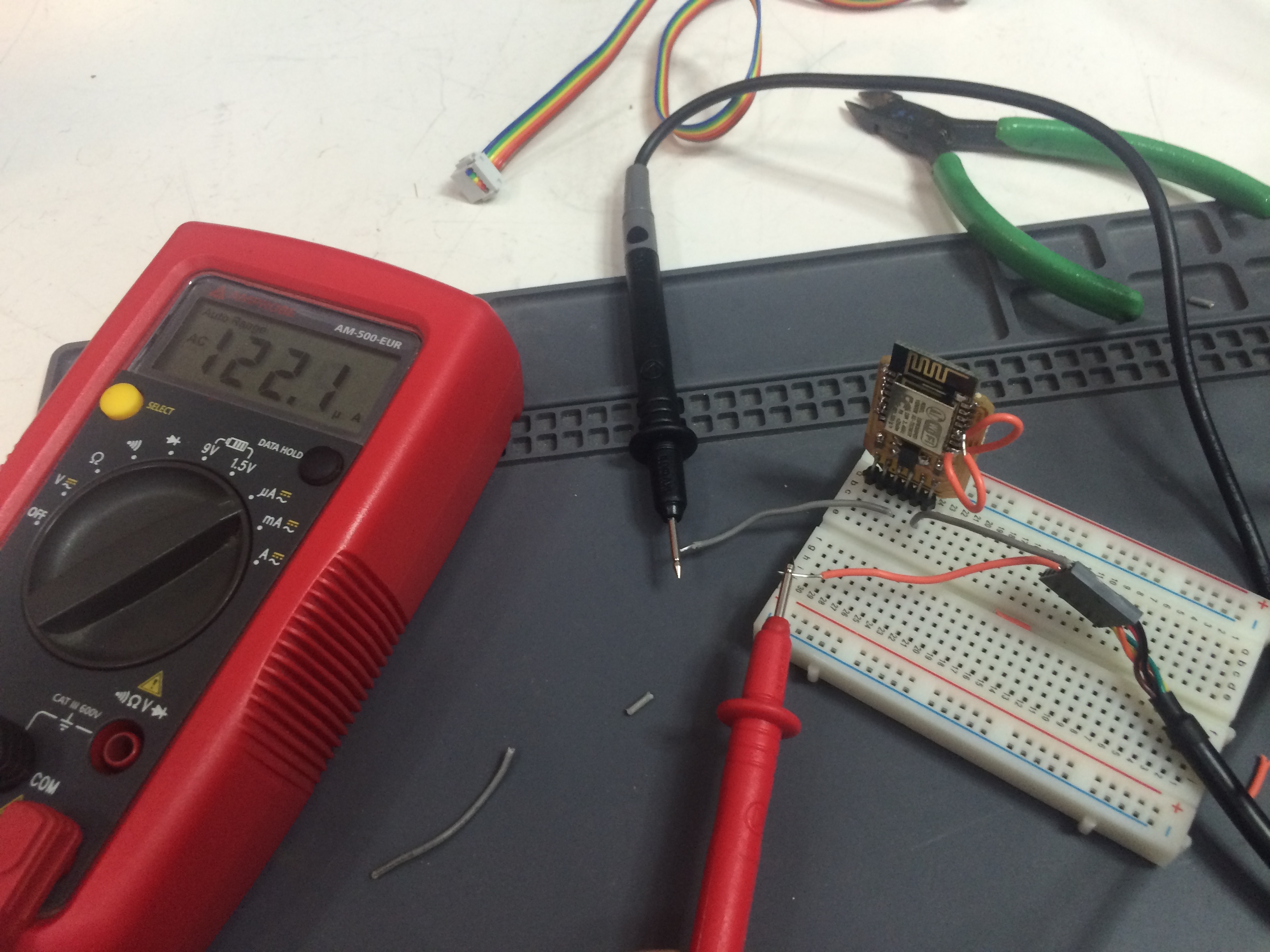
After stabilizing you can check the multimeter to see how much current it is drawing from the power source. In the case of an ESP8266 it was 122uA in sleep mode.
Individual assignment
RGB Led Shield v0.1
This is also a shield for my FabLeo, I used the same pin position to match. I used RGB addressable LEDs to output some lights. I made it on Eagle using the Fab library, it was a easy setup: a RGB LED has 4 “legs”, R, G B and GND. The color is set by combining the connectors to GND.
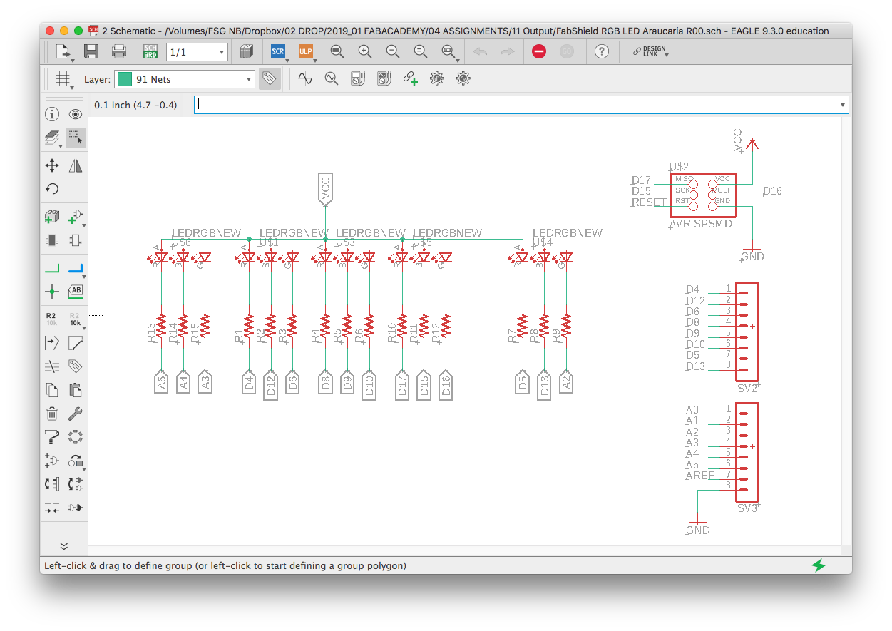
Each color needs a 1k resistor so I made one schematic, copied and pasted five times. I also connected each “leg” to a digital output of my board.
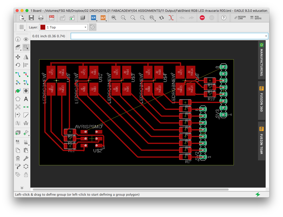
I finished the board design on Illustrator to make it a little more customized. I also had to draw a line to connect the GND.

After this was just a matter of milling and soldering like the other boards:
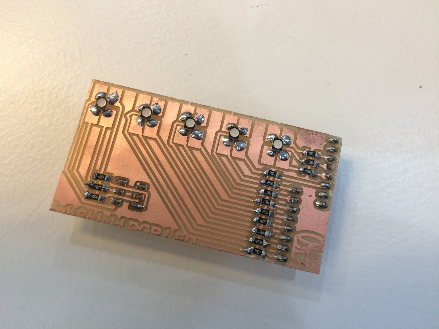
BOM:
- RGB LED x5
- R1K x15
Outputting light
You have to define the pins as R, G and B, so after you can set the pins as inputs in the setup. The loop is only the color definition, in this example I’m turning only the Red part of one RGB LED.
int redPin = 4;
int greenPin = 6;
int bluePin = 12;

void setup()
{
pinMode(redPin, OUTPUT);
pinMode(greenPin, OUTPUT);
pinMode(bluePin, OUTPUT);
}

void loop()
{
setColor(255, 0, 0);
}
After this I copied and pasted four times more and changed the names of the definitions to call different LEDs and colors.
int redPin2 = 14;
int greenPin2 = 16;
int bluePin2 = 15;

int redPin3 = 8;
int greenPin3 = 10;
int bluePin3 = 9;
So you can setup and loop like the first one:
pinMode(redPin2, OUTPUT);
pinMode(greenPin2, OUTPUT);
pinMode(bluePin2, OUTPUT);

pinMode(redPin3, OUTPUT);
pinMode(greenPin3, OUTPUT);
pinMode(bluePin3, OUTPUT);
setColor2(255, 255, 0); // yellow
setColor3(255, 255, 0); // yellow
After this I introduced the delay function to make some animations. This is the final code:
int redPin = 4;
int greenPin = 6;
int bluePin = 12;

int redPin2 = 14;
int greenPin2 = 16;
int bluePin2 = 15;

int redPin3 = 8;
int greenPin3 = 10;
int bluePin3 = 9;

int redPin4 = 5;
int greenPin4 = A2;
int bluePin4 = 13;

int redPin5 = A5;
int greenPin5 = A3;
int bluePin5 = A4;

void setup()
{
pinMode(redPin, OUTPUT);
pinMode(greenPin, OUTPUT);
pinMode(bluePin, OUTPUT);

pinMode(redPin2, OUTPUT);
pinMode(greenPin2, OUTPUT);
pinMode(bluePin2, OUTPUT);

pinMode(redPin3, OUTPUT);
pinMode(greenPin3, OUTPUT);
pinMode(bluePin3, OUTPUT);

pinMode(redPin4, OUTPUT);
pinMode(greenPin4, OUTPUT);
pinMode(bluePin4, OUTPUT);

pinMode(redPin5, OUTPUT);
pinMode(greenPin5, OUTPUT);
pinMode(bluePin5, OUTPUT);
}
void loop()
{
setColor(255, 0, 0); // red
delay(50);
setColor2(255, 0, 0); // red
delay(50);
setColor3(255, 0, 0); // red
delay(50);
setColor4(255, 0, 0); // red
delay(50);
setColor5(255, 0, 0); // red
delay(50);

setColor(0, 0, 0); // off
delay(50);
setColor2(0, 0, 0); // off
delay(50);
setColor3(0, 0, 0); // off
delay(50);
setColor4(0, 0, 0); // off
delay(50);
setColor5(0, 0, 0); // off
delay(50);

setColor(255, 255, 0); // yellow
delay(50);
setColor2(255, 255, 0); // yellow
delay(50);
setColor3(255, 255, 0); // yellow
delay(50);
setColor4(255, 255, 0); // yellow
delay(50);
setColor5(255, 255, 0); // yellow
delay(50);

setColor(0, 0, 0); // off
delay(50);
setColor2(0, 0, 0); // off
delay(50);
setColor3(0, 0, 0); // off
delay(50);
setColor4(0, 0, 0); // off
delay(50);
setColor5(0, 0, 0); // off
delay(50);

setColor(0, 255, 0); // green
delay(50);
setColor2(0, 255, 0); // green
delay(50);
setColor3(0, 255, 0); // green
delay(50);
setColor4(0, 255, 0); // green
delay(50);
setColor5(0, 255, 0); // green
delay(50);

setColor(0, 0, 0); // off
delay(50);
setColor2(0, 0, 0); // off
delay(50);
setColor3(0, 0, 0); // off
delay(50);
setColor4(0, 0, 0); // off
delay(50);
setColor5(0, 0, 0); // off
delay(50);

setColor(0, 0, 255); // blue
delay(50);
setColor2(0, 0, 255); // blue
delay(50);
setColor3(0, 0, 255); // blue
delay(50);
setColor4(0, 0, 255); // blue
delay(50);
setColor5(0, 0, 255); // blue
delay(50);

setColor(0, 0, 0); // off
delay(50);
setColor2(0, 0, 0); // off
delay(50);
setColor3(0, 0, 0); // off
delay(50);
setColor4(0, 0, 0); // off
delay(50);
setColor5(0, 0, 0); // off
delay(50);

setColor(255, 0, 255); // purple
delay(50);
setColor2(255, 0, 255); // purple
delay(50);
setColor3(255, 0, 255); // purple
delay(50);
setColor4(255, 0, 255); // purple
delay(50);
setColor5(255, 0, 255); // purple
delay(50);

setColor(0, 0, 0); // off
delay(50);
setColor2(0, 0, 0); // off
delay(50);
setColor3(0, 0, 0); // off
delay(50);
setColor4(0, 0, 0); // off
delay(50);
setColor5(0, 0, 0); // off
delay(50);

setColor(0, 255, 255); // aqua
delay(50);
setColor2(0, 255, 255); // aqua
delay(50);
setColor3(0, 255, 255); // aqua
delay(50);
setColor4(0, 255, 255); // aqua
delay(50);
setColor5(0, 255, 255); // aqua
delay(50);

setColor(0, 0, 0); // off
delay(50);
setColor2(0, 0, 0); // off
delay(50);
setColor3(0, 0, 0); // off
delay(50);
setColor4(0, 0, 0); // off
delay(50);
setColor5(0, 0, 0); // off
delay(50);

}
This is only a matter of turning the pins on or off to have a color variation. Each pin is connected to R, G or B of each LED, if the pin has PWM (Pulse Width Modulation) capability it can modulate the signal so it can be dimmed and output the whole possible spectrum of the LED. In my case I don’t have many PWM pins but I still can set them high or low so I still have some color variation.
PWM is a method for generating an analog signal using a digital source and is used for a wide variety of control applications like controlling DC motors, valves, pumps, hydraulics and other mechanical and electrical parts.
In this case we can set the to values go from 0 to 255 to define the colors. In a pin without the PWM function it can output only 0 or 255, so it is off or on. You can still, for example, make the color Yellow by setting Red and Green to 255. In a PWM pin we can do, for example, Orange by setting Red to 200 and Green to 100.
You should not use PWM with pins that do not have this function.
As an example of the PWM function we can explore an Arduino library Fade example and adapt it to my board. Defining the R, G and B pins it’s easy to follow the library’s example to fade the three colors to create a white fade in / fade out.
int redPin = 5;
int greenPin = 6;
int bluePin = 13;          // the pins that are attached to LEDs

int brightness = 0;    // how bright the LED is
int fadeAmount = 5;    // how many points to fade the LED by

// the setup routine runs once when you press reset:
void setup() {
  // declare pins to be an output:
  pinMode(redPin, OUTPUT);
  pinMode(greenPin, OUTPUT);
  pinMode(bluePin, OUTPUT);
}

// the loop routine runs over and over again forever:
void loop() {

#ifdef COMMON_ANODE
red = 255 - red;
green = 255 - green;
blue = 255 - blue;
#endif

  // set the brightness of the pins
  analogWrite(redPin, brightness);
  analogWrite(bluePin, brightness);
  analogWrite(greenPin, brightness);

  // change the brightness for next time through the loop:
  brightness = brightness + fadeAmount;

  // reverse the direction of the fading at the ends of the fade:
  if (brightness == 0 || brightness == 255) {
    fadeAmount = -fadeAmount ;
  }
  // wait for 30 milliseconds to see the dimming effect
  delay(30);
}
This code (and the PWM function) in action: