Final Project
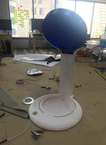
I have thought of creating a device that will be small, fun and beneficial to people. My initial idea is to design a coaster for mugs/bowls that will transfer or absorb heat between the coaster and the fluid container, which will result in maintaining the temperature of the drink as per preference. The sketch below will show a basic visual representation of the project.
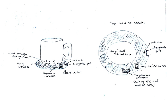
As seen above, the initial plan is that the coaster will have an ON/OFF switch which will activate the device. Next, the preferred temperature will be set by the user with the help of the temperature control knob (shown in top view), thus, allowing heat transfer to take place. The device can be used at any time unless it runs out of charge. An indicator will be present which will light up once the device is about to die, which can be later charged using a USB cable.
As mentioned earlier, this is just an initial plan of the project and further details have not yet been completely thought of. This project targets all members of the society since it serves a basic function and is safe to use by any age.
This thought was at an early stage in my journey in fabacademy. Progressing further, I thought of upgrading my design and developing it more to become like a real device. I thought of a design similar to the coffee machine but less complicated.
Design
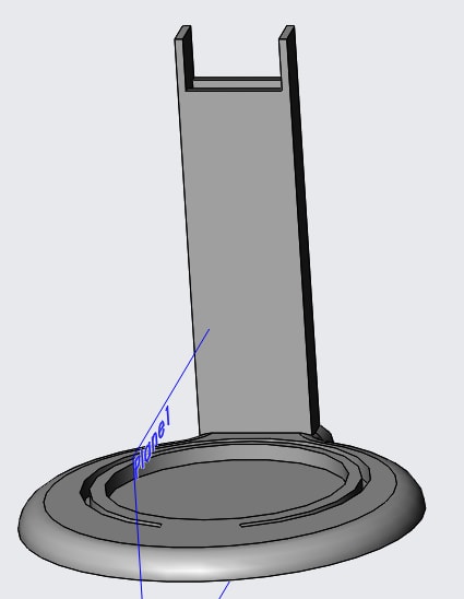
I am using solidworks to design my device. I will have a base which will hide the output circuit in it. On top of that will be the main body of the device to connect between the base and the top. There will be a middle part which will sit into the main body of my device in which it will hold the mug. Lastly, There will be a top lid to cover the mug which wil have the input circuit hidden in it. There will also be a mechanism to open and close the lid.
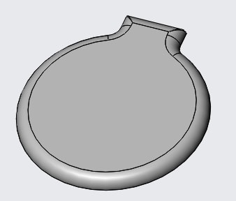
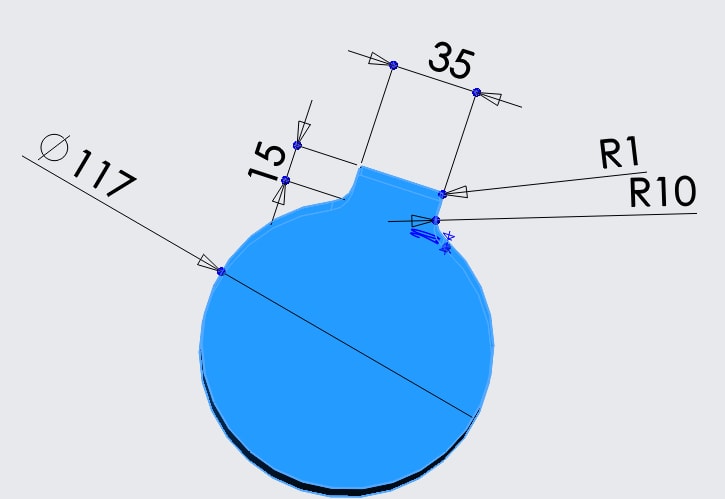
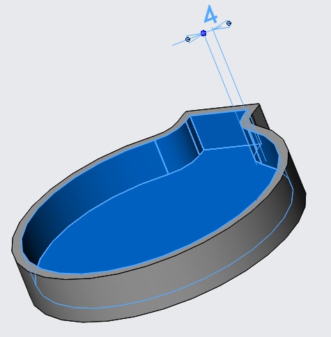
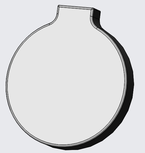
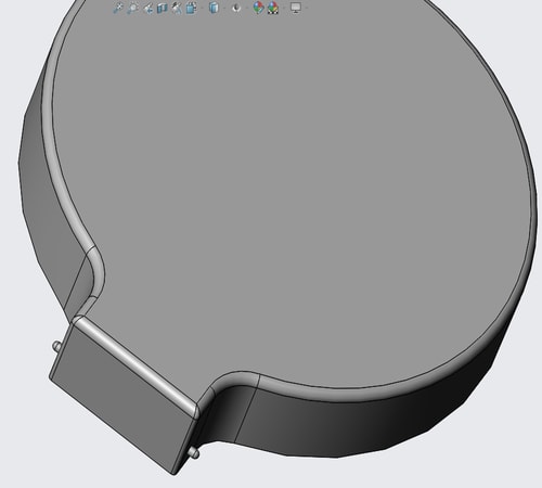
Base
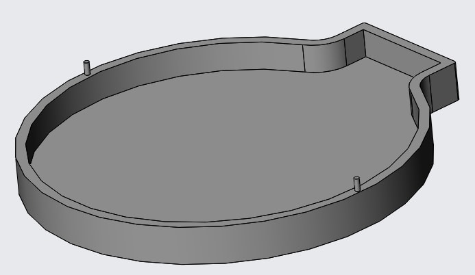

I used the shell feature to make it hollow with a wall thickness of 4 mm. I also did the little extruding cylinders on both side so that the body can sit on top of it.
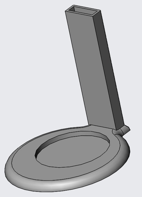
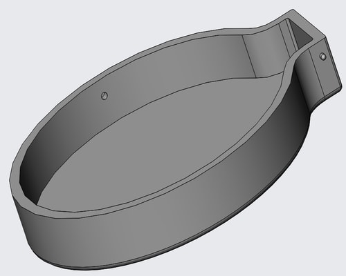
Main body
-
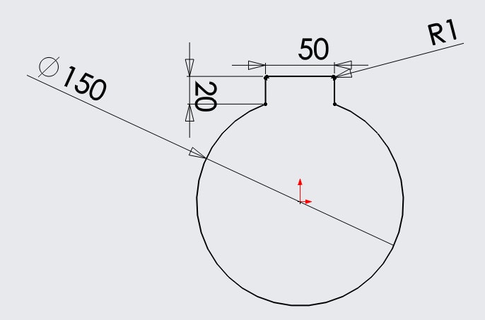
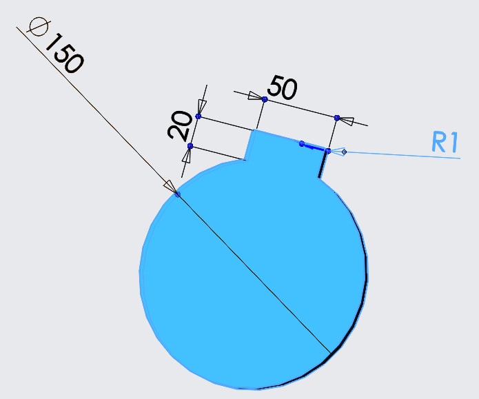
I started with the bottom part which will sit on top of the base.
-
I used the fillet feature to make the round edge.
-
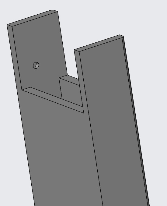
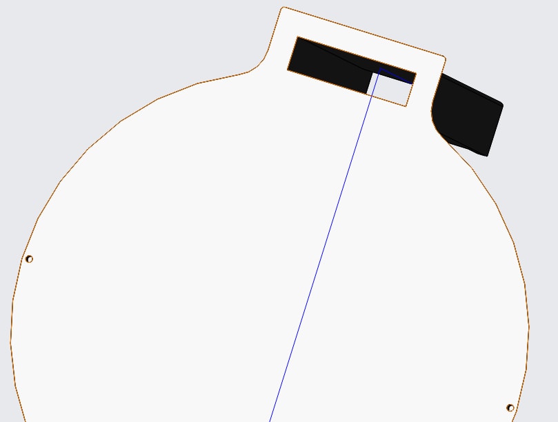
I did the circle cut so that the mug will be placed here and the rectangle cut so that the wires can pass through between the input circuit (placed on top) and output circuit ( placed in bottom).
-
This is to hold all the parts together and to hide any wires that will be passing.
-
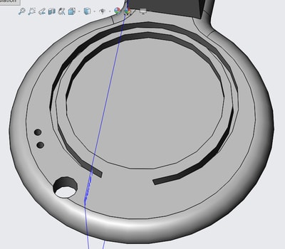
I did like a grooving in the bottom of the body so that I can place the centre part in which it will enclose the mug.
-
I removed a small piece at the top of the rectangle so that I can adjust the top lid here.
-
I did two holes so that I can insert the two extruding cylinders from the top lid here. This will help in the movement of the top lid for insterting the mug.
-
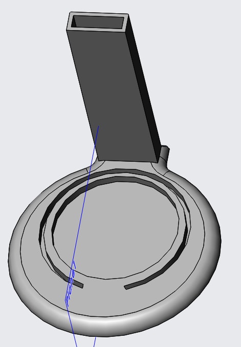
These holes are for the LEDs and potentiometer.
-
These holes are for the extrudings in the base so that the body will sit perfectly on top of the base.
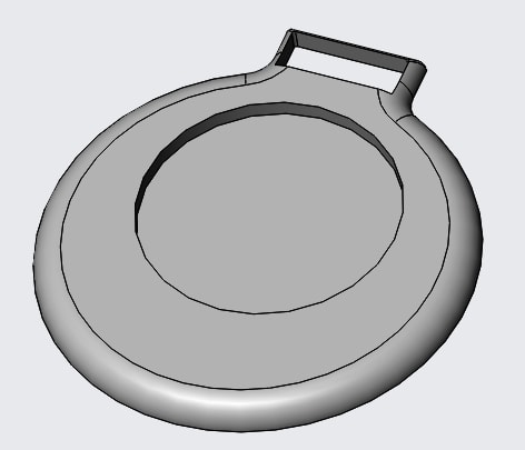
Top lid
-
I started out with the same structure as the base.
-
I used the shell feature to make it hollow with a wall thickness of 4 mm.
-
I used the fillet feature to make the round edge.
-
I did the extruding cylinders on the side so that I can attach it to the body.
-
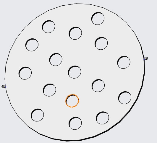
I did the holes on the side so that I can place a thin sheet here which will act as a barrier between the input circuit and the remaining device since I want the circuit to be hidden.
-
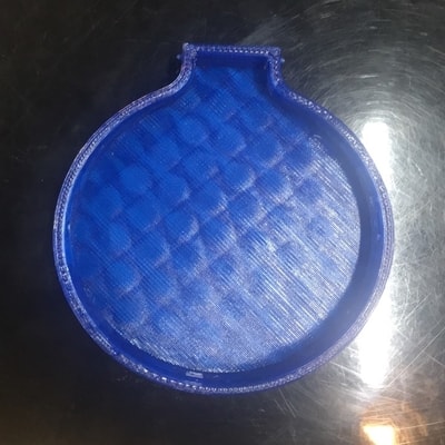
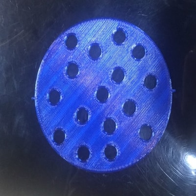
This is the sheet that I will place in the top lid. This is to hide the input circuit that will be placed inside. I purposely did random circle cuts all over so that the heat reaches the thermistor.
Centre piece
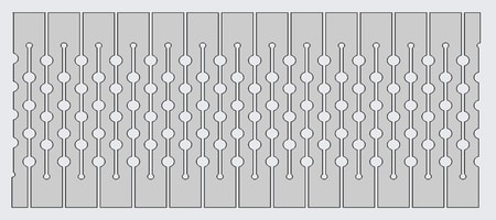
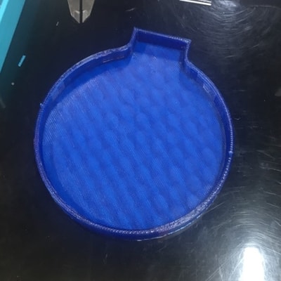
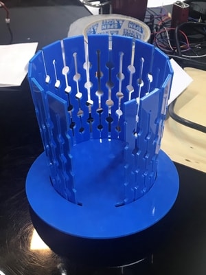
I did this design for my middle part so that I will be able to curve it since I will laser cut it.
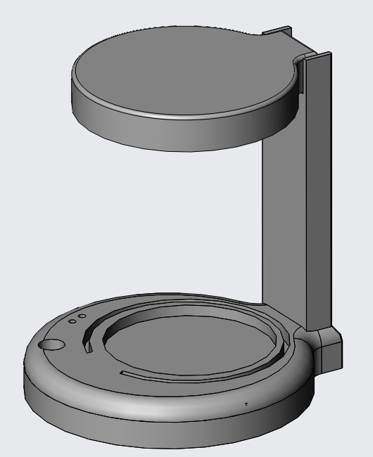
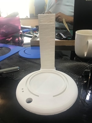
Finally, this is how the device will be looking like (excluding centre piece)
Manufacturing and fabrication
I decided to 3D print and laser cut to create my model.
The settings used for 3D printing
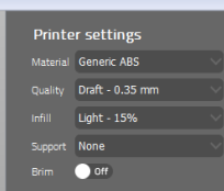
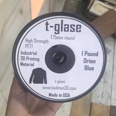
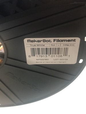
I used two materials for 3D printing, PETT and PLA with the exact same settings as shown above.
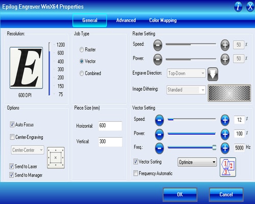
The settings used for laser cutting acrylic
Electronics design
Initial input ciruit
It consists of thermistor and hall effect sensors.
The thermistor is going to take the temperature of the drink and the hall effect sensor is going to sense whether the top lid is closed or open. This indication is going to initiate the whole programming. Once the lid is closed, it will send a signal to the thermistor to start taking temperature readings upon the given time interval. Basic programming of these two sensors have been done. Details of how I designed and programmed the circuit are in this page.
Problems faced
I was trying to communicate between the two circuits but I wasnt able to get proper data. My output circuit was working fine but I was able to get data from the thermistor although it works fine separately. The problem I faced here was that I did not know how to write a code that would read two digits instead of one, since temperature will be in two digits. I tried looking into many websites and tutorials to help me do it but it did not give me proper reading.
Here are the websites that I looked into:
- Convert int to char
- Sending variables over serial
- Sending multiple values to arduino through serial
- Sending and receiving multi digit integers
- Simple arduino serial communication
- Text to deciaml converter
Therefore, after not being able to make it work, I did not want to waste more time into it and decided to solder a thermistor into a veroboard for reading the temperature. This will later on be connected to the FTDI header of the output circuit using jumpers.
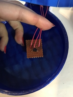
Final input circuit
This is the website that I followed to help me solder the connections properly by identifying which pin is gnd, vcc and analog voltage out and this is the website that I followed to help me with programming it.
Output circuit
Initial circuit
Consists of potentiometer, heating pad and 2 LEDs.
The potentiometer is a method for the user to choose its desired heating temperature by rotating the knob. The 2 LEDs will indicate the heating process. Red LED to indicate heating is taking place and green LED to indicate that the desired temperature has been reached. The heating pad is going to heat the drink. However, the heating pad that I tested with was only able to reach at a temperature of 36 degree celsius, therefore, I have found another material to heat up my drink with, which is the carbon fibre. These fibre strands work on low voltage, which is exactly what I want since I will be powering up my device using usb port (5V) and drags high current through them which will be able to heat up to a high temperature. Details of how I designed and programmed the circuit are in this page.
This was a test done with the carbon fibre to show how high in temperature it can reach.
I just took a small piece of carbon fibre and covered it in copper tape so that it conducts heat while I place it inside my model. As it is shown in the video, I only passed 4V to it and it was able to heat up upto 100 degree celsius.
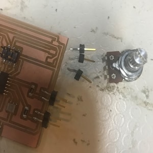
Problems faced
While programming the circuit in order to communicate with the input circuit, my potentiometer started getting loose since I was rotating it alot and testing the code plenty of times. I resoldered it couple of times but it still didnt work properly. I even noticed my LEDs light up at times were they were not supposed to light. I continued to upload the code without changing anything but nothing worked. I resoldered the potentiometer again for the last time and uploaded the code. I started rotating the potentiometer and noticed that it was heating up. Then, few seconds later, a burning small came out of the circuit and so I disconnected the power supply from it.
Finally, I decided to create new circuit where I can think of every aspect again and design it in a more organised and neater way to avoid any future problems.
Details about the networking and communication code will be found below.
Final circuit
Schematic diagram
I redesigned my output circuit by editing the initial circuit that I have done for the assignment. The schematic below is the new output circuit.
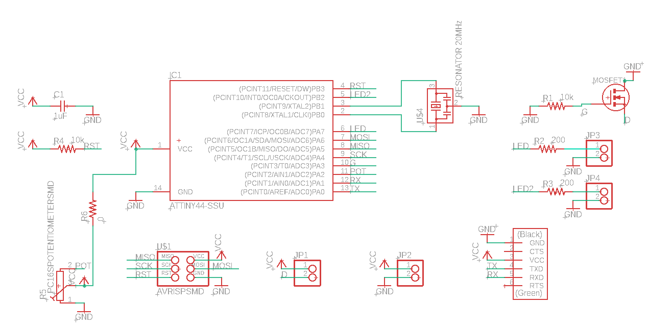
The changes that I have done in the new circuit is that I have removed the usb and created a seperate circuit for it and added four 1x2 pin headers in the areas where I will be using jumpers to connect. I will solder the jumper into the headers and place a heat shrink on top of it to secure everything.
The areas that I placed headers were:
- Connection for carbon fibre to the circuit.
- Connection of the two LEDS to the ciruit.
- Connection for the usb circuit to the output circuit.
The reason for using jumpers for these components is because I dont want them to have a fixed place in the circuit. I wanted them to be flexible since I will places them accorcingly depending on the design. Therefore, I decided to go with jumper connection.
For the pin headers, I used a separate library that had a footprint of a 1x2 pin header.
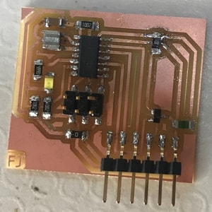
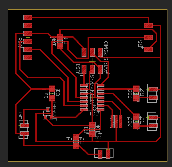
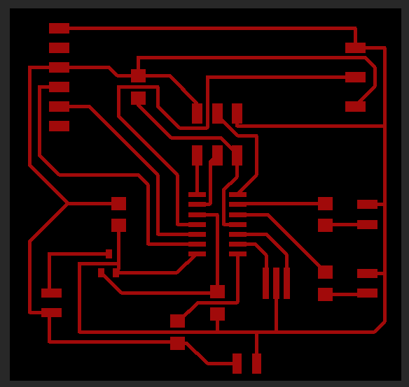
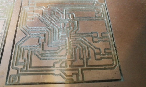
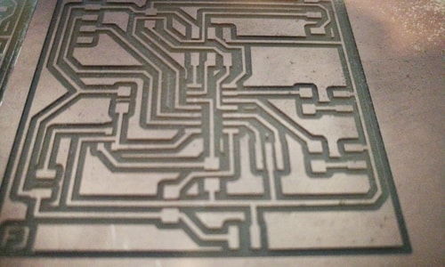
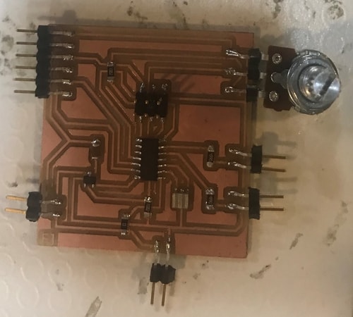
PCB design
The below image shows the PCB design of the circuit. There are no major changes in the circuit except that the usb was removed. Instead of the through hole LEDS, 1x2 pin headers were placed. Another pin header was placed for the carbon fibre and finally the last one was placed at the bottom centre of the circuit for the usb circuit connection.
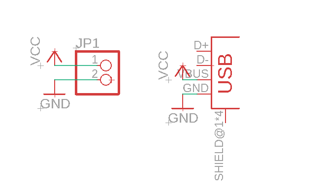
USB circuit schematic diagram
This circuit was only created so that I can place the usb port any where I want in my model. I also placed a 1x2 pin header connection so that I can connect it to the output circuit. Thus, it will get powered from the output circuit.
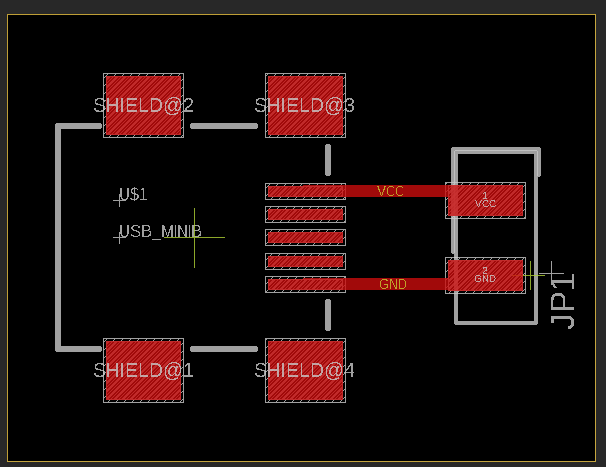
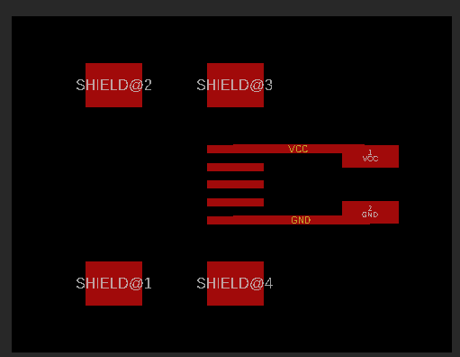
USB PCB design
Exporting the PCB
Go to ‘View’ > ‘Layer settings’ and select hide layers. This will remove all the layers on your board. You only want to show the top layer. Therefore just click on the left side of the ‘Top Layer’ row, so that the eye icon appears. Something like the image below will be displayed.
Then go to ‘File’ > ‘Export’ > ‘Image’ and change the resolutions settings to 500 DPI and select the monochrome. This will give a black and white image.
Editing the board
After exporting, I opened the image using GIMP to edit it.
- Go to ‘Image’ > ‘Canvas size’.
- Link the width and the height together by clicking on the link icon at the right of the boxes. Then add 20 px to the width. Automatically the height will change as well.
- In the Offset settings, click on centre to centre your image.
- When you’re done, click Resize.
- Go to ‘Image’ > ‘Flatten image’.
- This created a white border around your image which will be considered as your board outline.
-
Save the file. This is the file that you will use to create the traces. You can add a white text if you want and it will be milled out with the traces.
-
Use the bucket tool with black colour to fill in all the traces and only keeping the white outline.
-
Save this as a separate file since this will be used to mill out the outline.


Milling the board
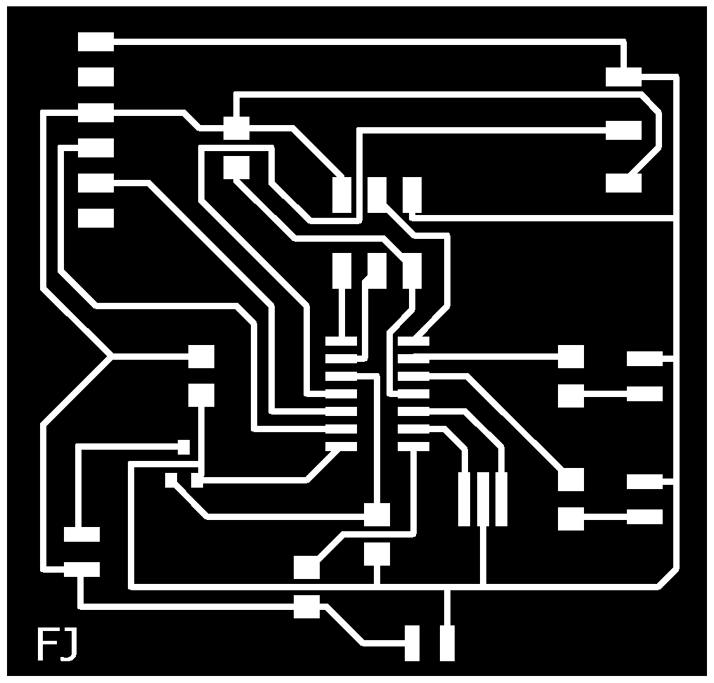
After saving the the png images, I used Fab Modules to prepare them for milling.
Traces
- Insert image as png.
- Choose the output format as the machine you’re using for milling. In my case it was Roland mill (.rml)
- Choose the process as PCB traces (1/64).
- Adjust the output settings found at the right side of the image.
- Set the machine. In my case it was SRM-20
- Speed: 3mm/s
- x0: 0mm
- y0: 0mm
- z0: 0mm
- zjog: 12mm
- Click calculate and the image preview will show how the traces will get milled.
- Click save.
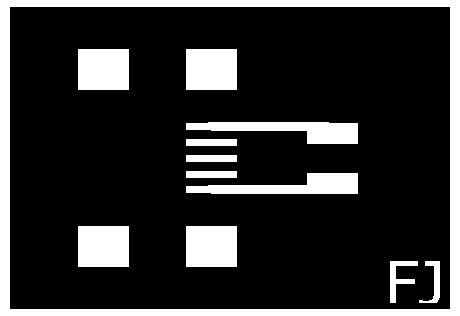
Outline
- Insert image as png.
- Choose the output format as the machine you’re using for milling. In my case it was Roland mill (.rml)
- Choose the process as PCB outline (1/32).
- Adjust the output settings found at the right side of the image.
- Set the machine. In my case it was SRM-20
- Speed: 0.5mm/s
- x0: 0mm
- y0: 0mm
- z0: 0mm
- zjog: 12mm
- Click calculate and the image preview will appear.
- Click save.
Open the VPanel to adjust the origin settings manually before milling. This defines the starting point of where the drill bit will be to start cutting. After adjusting the origins, allow the spindle to spin for 5 minutes atleast and then add the file you want mill and click on cut. Dont forget to change the drill bit while milling the traces and outline. The tool bit for traces is 1/64 and for outline is 1/32.
Soldering
Tools used:
- Sharp tweezers
- Solder flux pen
- Solder iron
- Solder
Components used:
- 20 MHz Resonator
- 0 ohm Resistor
- 2 10k ohm Resistor
- 2 200 ohm Resistor
- N channel Mosfet
- 1uF Capacitor
- IC1 ATTiny84
- FTDI header
- AVRISPSMD (2x3)
- 5 1x2 Pin headers
- Carbon fibre
- Red LED
- Green LED
- Potentiometer
- USB mini B
Programming
I used Arduino IDE to program my circuit. I started by testing my potentiometer just like my initial output circuit, using the same code i used earlier.
this is an exmaple of the code i used.
#include <SoftwareSerial.h>
#define RX PA1
#define TX PA0
const int potentiometerPin = PA2;
SoftwareSerial mySerial(RX, TX);

void setup()
{
mySerial.begin(9600);
pinMode(potentiometerPin, INPUT);
}

void loop() {
// read the potentiometer value:
int potentiometerState = analogRead(potentiometerPin);

mySerial.println(potentiometerState);
}
Here is a video of it working.
Materials and prices
| Qty | Part name | Description | Total Price ($) |
|---|---|---|---|
| 2 | IC1 ATtiny84 | Microcontroller smd | 1.48 |
| 2 | Resonator | 20 mhz smd | 0.6 |
| 2 | Capacitor | 1uF smd | 0.1 |
| 2 | Resistor | 0 ohm smd | 0.2 |
| 6 | Resistor | 10k ohm | 3.6 |
| 4 | Resistor | 499 ohm | 1.4 |
| 1 | Thermistor | sensor | 3.04 |
| 1 | Hall effect | sensor | 0.7 |
| 1 | Potentiometer | sensor | 0.95 |
| 1 | N channel mosfet | transistor | 0.6 |
| 2 | 2x3 pin header | AVRISPSMD | 0.3 |
| 1 | 2x2 pin header | AVRISPSMD | 0.15 |
| 2 | 1x6 pin header | FTDI header | 0.3 |
| 1 | Heating Pad | 5x10 cm | 3.95 |
| 1 | Usb B mini | - | 0.99 |
| 1 | LED | White smd indicator | 0.63 |
| 1 | LED | Green through hole indicator | 0.64 |
| 1 | LED | Red through hole indicator | 0.64 |
| 2 | PCB | Circuit board | 1.4 |
Networking and communication
I had started some bits and pieces in the communication assignment earlier to ensure that the two circuits can successfully communicate with each other. I did something similar to what I actually want but less complicated. I did the connection using serial communication between two attiny boards. So what the code does is that if the potentiometer (output circuit) reads a value of 500 or greater
- It will show the number 1 in the serial monitor
- Red LED (output ciruit) will turn on and white LED (input circuit) will turn on.
Otherwise, if the potentiometer reads a value of less than 500, the green LED will only turn on.
Here is a video of how it worked and detailed information is present in the communication assignment week.
For my actual communication process that I require for my final project, I would want my circuit to do the following:
- User chooses a desired temperature by rotating the knob of the potentiometer.
- Thermistor will compare the desired temperature with the actual temperature.
- If the temperature is lower than the desired temperature, the heating pad will start to heat up and the red LED will turn on. This indicates that heating is taking place.
- Thermistor will continue to take readings every 5 seconds for instance. Once the desired temperature has been reached, the heating will stop, red LED will turn off and the green LED will turn on. This indicates that the desired temperature has been reached.
- Hall effect sensor can sense when the lid is closed and can initiate the thermistor to start taking readings and start the heating process. Once the lid is open, heating will stop.
Therefore, I combined the two codes together (thermistor and potentiometer) and edit it to program the circuit they way I mentioned it above.
Initial communication
This is the example of the code I used initially when I stared to program my board in order to communicate with each other. But unfortunately, I faced the issue where my potentiometer burned and had to do a new circuit all over again.
#include <SoftwareSerial.h>
#define RX PA1
#define TX PA0
#define RX1 PA6
#define TX1 PA5
#define red PA7
#define green 8
#define heat PA3
int v;
char TT;

const int potentiometerPin = PA2;
SoftwareSerial mySerial(RX1, TX1);
SoftwareSerial mymonitor(RX, TX);


void setup()
{
mySerial.begin(9600);
mymonitor.begin(9600);
pinMode(potentiometerPin, INPUT);
pinMode(red, OUTPUT);
pinMode(green, OUTPUT);
pinMode(heat, OUTPUT);
mymonitor.println("intilize");
}

void loop() {
// read the potentiometer value:
TT = mySerial.read();
int T = TT;
T = T - 15;
int potentiometerState = analogRead(potentiometerPin);
int y = map(potentiometerState, 0, 1023, 0, 50);
mymonitor.println(y);
mymonitor.println(T);
mymonitor.println(TT);
mySerial.println(y);

if (T<y){
  digitalWrite(heat, HIGH);
  digitalWrite(red, HIGH);
   digitalWrite(green, LOW);
}

else {

   digitalWrite(heat, LOW);
  digitalWrite(green, HIGH);
  digitalWrite(red, LOW);
}
}
I referred to this website to show me how to map my potentiomoeter.
Final communication
After doing my new circuit, I had to modify the code slightly since im no longer using my previous input circuit for the temperature reading. Therefore, the new code will be shown below.
#include <SoftwareSerial.h>
#define RX PA1
#define TX PA0

#define red PA7
#define green 8
#define heat PA3
int sensorPin = PA0;
int sensorInput;    //The variable we will use to store the sensor input
double temp;        //The variable we will use to store temperature in degrees.
const int potentiometerPin = PA2;


void setup()
{
pinMode(potentiometerPin, INPUT);
pinMode(red, OUTPUT);
pinMode(green, OUTPUT);
pinMode(heat, OUTPUT);
}

void loop()
{
 sensorInput = analogRead(PA0);    //read the analog sensor and store it
  temp = (double)sensorInput / 1024;       //find percentage of input reading
  temp = temp * 5;                 //multiply by 5V to get voltage
  temp = temp - 0.5;               //Subtract the offset
  temp = temp * 100;               //Convert to degrees
int potentiometerState = analogRead(potentiometerPin);
int y = map(potentiometerState, 0, 1023, 0, 50);

if (temp<y){
  digitalWrite(heat, HIGH);
  digitalWrite(red, HIGH);
   digitalWrite(green, LOW);
}

else {

   digitalWrite(heat, LOW);
  digitalWrite(green, HIGH);
  digitalWrite(red, LOW);
}
}
This is a video showing when the voltage passes into the heating element pin to initiate its heating process.
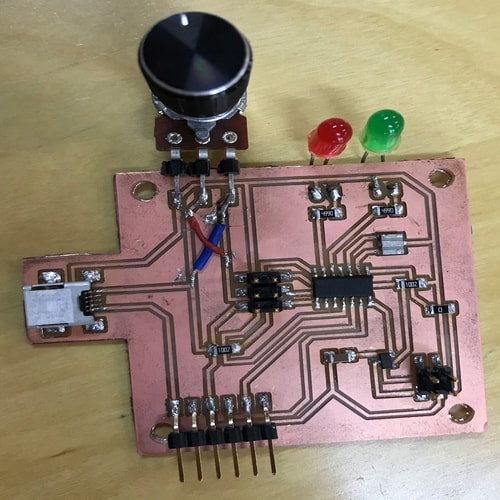
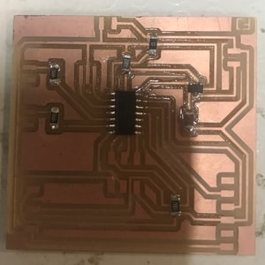
Assembling
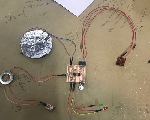
Here is the entire circuit after everything has been soldered in place.
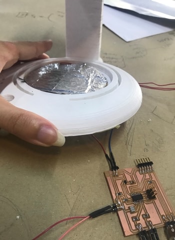
Assembling of carbon fibre (heating element) into the model.
Assembling of LED into the model.
Assembling of thermistor into the model.
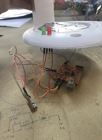
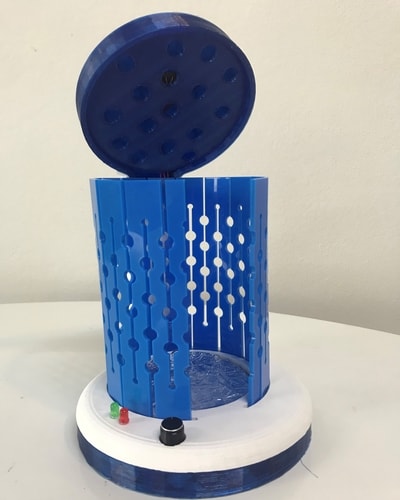
And finally, here is an image of the device after I assembled all the parts together.
The video below will show the testing of the project. A mug filled with hot water was placed inside the device and switched on using the usb cable from the laptop. The green led automatically turns on since the thermistor senses that the temperature is already high and there’s no need for heating the drink more.
Then the video here shows after a while when the drink has been cooled down, the red led turns on since its indicating that the temperature set by the user is higher than the drink temperature and so it turns the heating element on in order to heat the drink. The video will show how the temperature of the heating pad is icreasing.
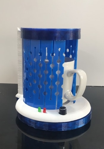
Finally, a comparison was done between two mugs filled with hot water. One mug will be placed inside the device and the other one will be just placed on the table. The temperature above the hot water was initially taken and shown in the video.
The potentiometer was set to the maximum temperature, which is 50 degree celsius so that it provides continuous heat supply in order to keep the drink warm.
Here it shows how the temperature of both the mugs changed after 7 and 15 minutes. It can be seen from the video that the drink inside the device almost maintained its temperature since there was continuos heat supply provided from the device and the drink placed on the table was getting cooler.
Click here to download the solidworks files
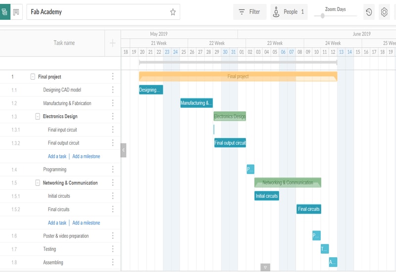
Gantt Chart
License
The idea was first generated to be a coaster that reheats beverages. With further research and creativity into the fablab environment, the design got modified to a bigger scale device which looks almost similar to a coffee machine.
I came up with this idea because I like to have my beverages quite warm wherever during working hours since I tend to forget about them while working. Thermostats used to do the job up to a certain time but would eventually cool down.
For the future, I’m thinking of modifying my design to incorporate a larger scale of cups with different sizes by developing a mechanism which will be able to provide the flexibility in adjusting the top lid on top of the mug, depending on the users mug. My target is to develop my design in such a way that it would suitable for homes, offices, hotels, airports etc.
In order to achieve this, I will first test out my current device non-commercially to different environment. This would help in gathering different informations and perspectives which will allow me to enhance the device even more.
Finally looking at it from a business perspective, licensing is a must. I will be looking into fablab licence or the MIT license. With MIT, licensing anything could be done as long as I include the original copyrights.
Here is my final poster

And this is the video of my final project