11. Input devices
This Weeks Task:
Group Assignment
- Probe an input device’s analog levels and digital signals.
Individual Assignment
- Measure something: add a sensor to a microcontroller board that you have designed and read it.
Group Assignment
Here is a link to the group assignment page.
Individual Assignment
For this week, I designed my input circuit for my final project. My project will be about maintaining the heat in a cup of a hot drink, therefore I will be using a type of temperature sensor. The other input that I have added into my project is the hall effect sensor, which is magnetic. This will be placed on top of my design in order to attract the lid which will cover the top part of the cup. As a result, the two input devices that I have used are:
The third input device that I will use is the potentiometer. I have done it with the output circuit since it will be easier for my project design later. Here is a link to the output circuit design.
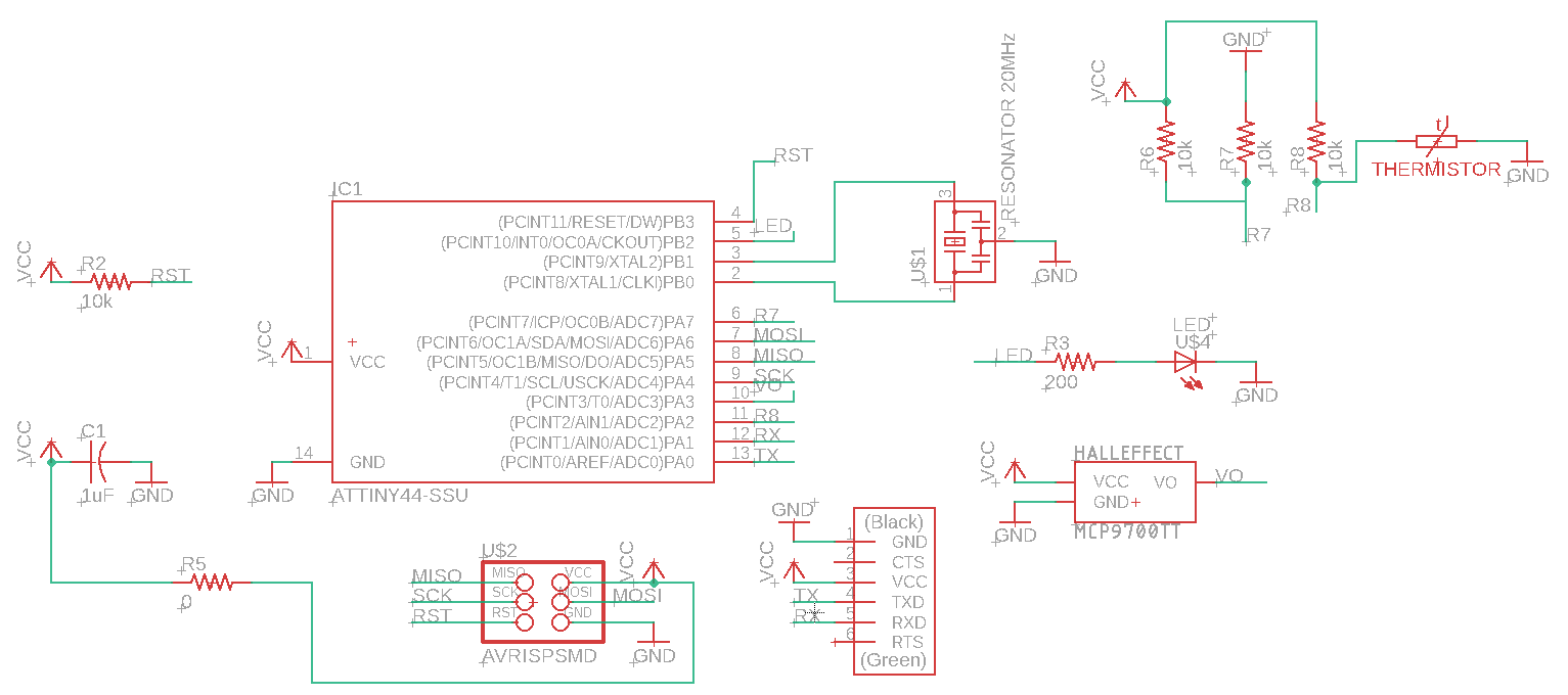
Schematic diagram
To start of with the schematic, I edited my echo hello world according to what I require for my circuit. Instead of the button, I added the thermistor and the hall effect sensors. In addition, I referred to the attiny44 datasheet to help me identify which pins have ADC for connecting the thermistor to since I had limited amout of pins left on the my attiny44. I had to research and read the datasheets of my sensors to find out if my sensors both give out analog signals or not. I then came back to the attiny44 datasheet and connected the thermistor pins to ADC pins specifally since the hall effect sensor gives our digital signals.
To add these sensors in the schematic, I had to download their libraries since they were not available neither in the existing eagle libraries nor the fab library.
The libraries I used were:
You can use any different website you find to download your libraries and directly click on download. In my case, these websites did not have any download option, therefore, I did the following steps to save the library.
Steps to download library
- Open the page mentioned above and select the entire text.
- Paste it in any text editor application. I used notepad. Save the file with any name you want and add the extension as .lbr. For instance, “Thermistor.lbr”, this will automatically save the file as library as eagle library format. Save it in your desired folder.
- Go to Eagle and open the schematic.
-
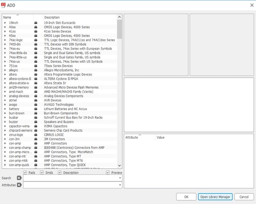
Click on add part from the toolbar, then click on open library manager.
-
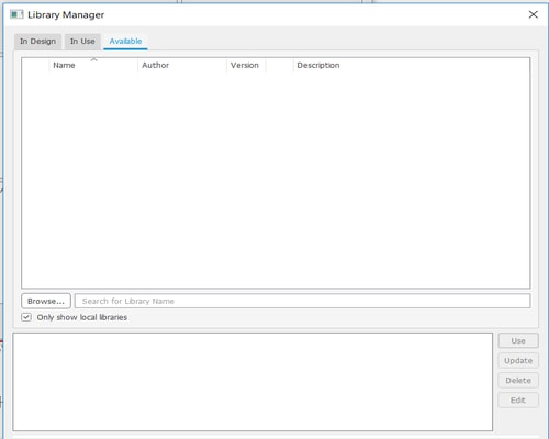
Go to Available in the top menu and click on Browse.
-
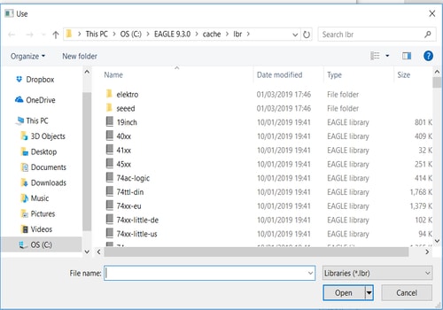
Select the library from the folder you saved it in.
-
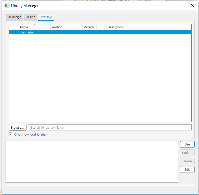
Click on the library to select it and then click on Use. The library will automatically be added.
-
Close the library manager and chose the part you want from the library.
This is the final schematic drawing. Download schematic file
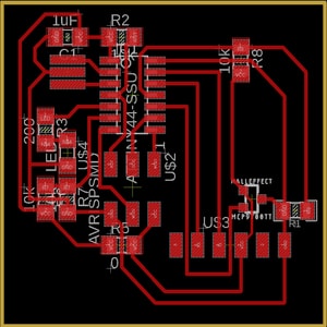
PCB design
Go to File>Switch to board to start with the pcb design. I adjusted the components and created the routing and below will be the final pcb design.
Exporting the PCB
Go to ‘View’ > ‘Layer settings’ and select hide layers. This will remove all the layers on your board. You only want to show the top layer, therefore just click on the left side of the ‘Top Layer’ row, so that the eye icon appears. Something like the image below will be displayed.
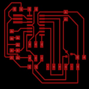
Then go to ‘File’ > ‘Export’ > ‘Image’ and change the resolutions settings to 500 DPI and select the monochrome. This wil give you a black and white PNG image.
Editing the board
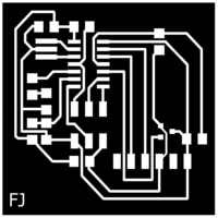
After exporting, I opened the image using GIMP to edit it.
- Go to ‘Image’ > ‘Canvas size’.
- Link the width and the height together by clicking on the link icon at the right of the boxes. Then add 20 px to the width. Automatically the height will change as well.
- In the Offset settings, click on centre to centre your image.
- When you’re done, click Resize.
- Go to ‘Image’ > ‘Flatten image’.
- This created a white border around your image which will be considered as your board outline.
-
Save the file. This is the file that you will use to create the traces. You can add a white text if you want and it will be milled out with the traces.
-
Use the bucket tool with black colour to fill in all the traces and only keeping the white outline.
-
Save this as a separate file since this will be used to mill out the outline.

Milling the board
After saving the the png images, I used Fab Modules to prepare them for milling.
Traces
- Insert image as png.
- Choose the output format as the machine you’re using for milling. In my case it was Roland mill (.rml)
- Choose the process as PCB traces (1/64).
- Adjust the output settings found at the right side of the image.
- Set the machine. In my case it was SRM-20
- Speed: 3mm/s
- x0: 0mm
- y0: 0mm
- z0: 0mm
- zjog: 12mm
- Click calculate and the image preview will show how the traces will get milled.
- Click save.
Outline
- Insert image as png.
- Choose the output format as the machine you’re using for milling. In my case it was Roland mill (.rml)
- Choose the process as PCB outline (1/32).
- Adjust the output settings found at the right side of the image.
- Set the machine. In my case it was SRM-20
- Speed: 0.5mm/s
- x0: 0mm
- y0: 0mm
- z0: 0mm
- zjog: 12mm
- Click calculate and the image preview will appear.
- Click save.
Open the VPanel to adjust the origin settings manually before milling. This defines the starting point of where the drill bit will be to start cutting. After adjusting the origins, allow the spindle to spin for 5 minutes atleast and then add the file you want mill and click on cut. Dont forget to change the drill bit while milling the traces and outline. The tool bit for traces is 1/64 and for outline is 1/32.
Soldering
Tools used:
- Sharp tweezers
- Solder flux pen
- Solder iron
- Solder
Components used:
- 20 MHz Resonator
- 0 ohm Resistor
- 4 10k ohm Resistor
- 200 ohm Resistor
- Thermistor
- 1uF Capacitor
- IC1 ATTiny44
- J2 FTDI
- J1 AVRISPSMD
- Push button
- White LED
- Hall effect sensor
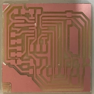
Here is an image of the pcb before soldering the components onto it.
Problems faced
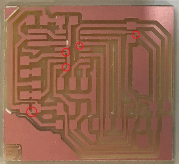
Aftering soldering the components, I tested the circuit by doing the continuity test using a multimeter and found connection between the gnd and the vcc, as well as some connections between the attiny pins. I referred back to the above milled circuit image to find out if the circuit was milled properly, and I found 5 connections that the bit did not remove. This is shown in the image below.
Therefore, I had to remove the components that had the connections underneath them and disconnect the connections between the traces using a small sharp blade. I did this step very carefully and precisely in order to prevent any damage to other copper traces without disconnecting anything. Although, I accidently disconnected a trace, but I managed to connect them using some solder.
I did remove the resistors by only placing the solder iron on the ends to melt the solder and then picked it up using a tweezer. However, this procedure was impossible with the attiny. Therefore, I had to use the heat gun to remove it. I placed the heat gun on top of the attiny and held it in the air using the tweezer. Once the solder is all dissolved, the pcb fell and the attiny remained in the tweezer.
Here are images of the areas in the pcb after I disconnected the traces from each other.
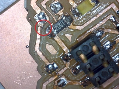
Here I accidently removed the copper track while trying to disconnect the other traces from each other, so I connected them with solder.
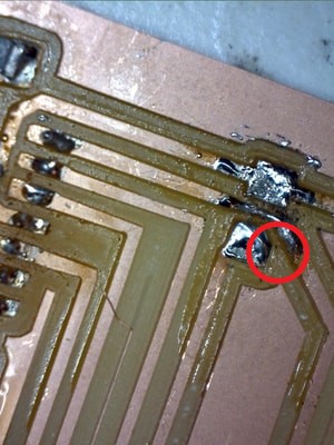
After removing the above connections, I still found a connection between the gnd and the vcc. Therefore, I tried to remove the last component that may have a possible connection between gnd and vcc. This component was a 0 ohm resistor that I placed since I had an overlapping route. After removing the component, I found that there was a small solder connecting the two traces together under the component in which it will be shown below. Therefore, I just removed the solder in between and there were no more any connections.

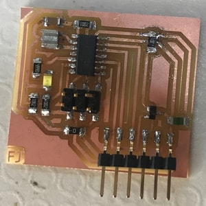
This is the final PCB.
Programming
I programmed my entire circuit using Arduino IDE.
Thermistor
Since I have done the same connections as Neil’s for the thermistor example, I thought of looking at his code to help me program my thermistor. However, since he is using a different language as I am, we tried understanding the code and the steps of how he did it and then tryping it down in the arduino ide.
This is an example of re-writing Neil’s code in arduino ide.
#include <SoftwareSerial.h>
#define RX PA1
#define TX PA0
SoftwareSerial mySerial(RX, TX);

// the value of the 'other' resistor
#define SERIESRESISTOR 10000

// What pin to connect the sensor to
#define THERMISTORPIN PA2
#define THERMISTORPIN1 PA7

void setup(void) {
  mySerial.begin(9600);
}

void loop(void) {
  float reading;
  float reading1;
  float value;
  float V, R;
  int B,  R25,T;

 reading = analogRead(PA2);
 reading1 = analogRead(PA7);


 value = reading - reading1;
  //if (value > 511){
  //    value = 1024;}
 V = 2.5 - value*5.0/(20.0*512.0);
  //V = value* 0.0049;
  // mySerial.println(V);
 R = 10000.0/(5.0/V-1.0);

  // NHQ103B375R5
  // R25 10000 (O)
  // B (25/85) 3750 (K)
  //R(T(C)) = R(25)*exp(B*(1/(T(C)+273.15)-(1/(25+273.15))));
  B = 3750;
  R25 =  10000;
  T = 1.0/(log(R/R25)/B+(1/(25.0+273.15))) - 273.15;
  mySerial.println(T);

  delay(1000);
}
The video below shows the result.
Here, the temperature reading can be clearly seen, which does implify that the code is right. However, the moment I touch the sensor to test whether it will give a higher temperature reading, it comes down to one degree low and remains constant throughout the process. I then tried using a heat gun to test how much the temperature will change and the result was shown in the above video.
Therefore, I tried using a different code in the adafruit website to test whether it will give me a better result. Unfortunately, it had the exact same result.
Example of the code I used
#include <SoftwareSerial.h>
#define RX PA1
#define TX PA0
SoftwareSerial mySerial(RX, TX);

// the value of the 'other' resistor
#define SERIESRESISTOR 10000

// What pin to connect the sensor to
#define THERMISTORPIN PA2
 #define THERMISTORPIN1 PA7

void setup(void) {
  mySerial.begin(9600);
}

void loop(void) {
  int reading;
   int reading1;
   int value;
      float V, R;
      int B,  R25,T;

  reading = analogRead(PA2);
 reading1 = analogRead(PA7);


    value = reading - reading1;
if (value > 511){
      value = 1024;}
   V = 2.5 - value*5.0/(20.0*512.0);
   R = 10000.0/(5.0/V-1.0);

   // NHQ103B375R5
   // R25 10000 (O)
   // B (25/85) 3750 (K)
   //R(T(C)) = R(25)*exp(B*(1/(T(C)+273.15)-(1/(25+273.15))));
   B = 3950;
   R25 =  10000;
  T = 1.0/(log(R/R25)/B+(1/(25.0+273.15))) - 273.15;
   //mySerial.println(T);


  float steinhart;
  steinhart = R / R25;     // (R/Ro)
  steinhart = log(steinhart);                  // ln(R/Ro)
  steinhart /= B;                   // 1/B * ln(R/Ro)
  steinhart += 1.0 / (25 + 273.15); // + (1/To)
  steinhart = 1.0 / steinhart;                 // Invert
  int steinhart1 = steinhart - 273.15;                         // convert to C

  mySerial.print("Temperature ");
  mySerial.print(steinhart1);
  mySerial.println(" *C");

  // convert the value to resistance
 // reading = (1023 / reading)  - 1;     // (1023/ADC - 1)

  //reading = SERIESRESISTOR / reading;  // 10K / (1023/ADC - 1)
//  mySerial.print("Thermistor resistance ");
 // mySerial.println(reading);

  delay(1000);
}
While skimming through the website again, I noticed that many people mentioned that the resistance equation is wrong. The sentence below was written in the website.
“Lots of people have emailed me to tell me the above equation is wrong and the correct calculation is R = 10K*ADC / (1023 - ADC). Their equivalence is left as an exercise for the reader! ;)”
So, I thought of trying this R equation instead of the one in the code example and it worked!
This is the final code example.
#include <SoftwareSerial.h>
#define RX PA1
#define TX PA0
SoftwareSerial mySerial(RX, TX);

// the value of the 'other' resistor
#define SERIESRESISTOR 10000

// What pin to connect the sensor to
#define THERMISTORPIN PA2
#define THERMISTORPIN1 PA7

void setup(void) {
  mySerial.begin(9600);
}

void loop(void) {
  float reading;
  float reading1;
  float value;
  float V, R;
  int B,  R25,T;

 reading = analogRead(PA2);
 reading1 = analogRead(PA7);


 value = reading - reading1;
  //if (value > 511){
  //    value = 1024;}
 V = 2.5 - value*5.0/(20.0*512.0);
  //V = value* 0.0049;
  // mySerial.println(V);
 R = 10000.0*((5.0/V)-1.0);

  // NHQ103B375R5
  // R25 10000 (O)
  // B (25/85) 3750 (K)
  //R(T(C)) = R(25)*exp(B*(1/(T(C)+273.15)-(1/(25+273.15))));
  B = 3750;
  R25 =  10000;
  T = 1.0/(log(R/R25)/B+(1/(25.0+273.15))) - 273.15;
  mySerial.println(T);

  delay(1000);
}
Hall Effect
I researched online to find example codes for the hall effect sensor and this was the code I used.
#include <SoftwareSerial.h>
#define RX PA1
#define TX PA0
SoftwareSerial mySerial(RX, TX);

const int hallPin = PA3;     // hall effect sensor out pin
const int ledPin =  8;    // LED pin

int hallState = 0;         // Initial hall sensor status

void setup() {
  mySerial.begin(9600);
  pinMode(ledPin, OUTPUT); // LED pin as an output

  pinMode(hallPin, INPUT); // The hall effect sensor pin as an input

}

void loop(){


  hallState = digitalRead(hallPin); // reading the state of the hall effect sensor pin

  if (hallState == LOW) {

    mySerial.println("detect");
    digitalWrite(ledPin, HIGH);  // turn LED on
  }
  else {

    digitalWrite(ledPin, LOW);  // turn LED off
  }
}
This example will light up the LED once it detects the magnet and show the word ‘detect’ in the serial monitor. However, the LED did not light up and instead of showing the word ‘detect’ it just showed ‘?’.
I thought of looking at what is happening exactly in the sensor by using the oscilloscope and found that there should not be any issues with it.
I tried playing around with the code and kept “mySerial.println(“detect”);” to show all the time and disappear when it detects a magnet. This time, it was showing the right data in the serial monitor, but, the LED did not light up at all, which im not sure why.
#include <SoftwareSerial.h>
#define RX PA1
#define TX PA0
SoftwareSerial mySerial(RX, TX);

const int hallPin = PA3;     // hall effect sensor out pin
const int ledPin =  8;    // LED pin

int hallState = 0;         // Initial hall sensor status

void setup() {
  mySerial.begin(9600);
  pinMode(ledPin, OUTPUT); // LED pin as an output

  pinMode(hallPin, INPUT); // The hall effect sensor pin as an input

}

void loop(){


  hallState = digitalRead(hallPin); // reading the state of the hall effect sensor pin

  if (hallState == LOW) {

    digitalWrite(ledPin, HIGH);  // turn LED on
  }
  else {

    mySerial.println("detect");
    digitalWrite(ledPin, LOW);  // turn LED off
  }
}
Finally, I tried reversing the code by letting the LED to light up all the time and turn off when it detects a magnet, and show detect in the serial monitor.
#include <SoftwareSerial.h>
#define RX PA1
#define TX PA0
SoftwareSerial mySerial(RX, TX);

const int hallPin = PA3;     // hall effect sensor out pin
const int ledPin =  8;    // LED pin

int hallState = 0;         // Initial hall sensor status

void setup() {
  mySerial.begin(9600);
  pinMode(ledPin, OUTPUT); // LED pin as an output

  pinMode(hallPin, INPUT); // The hall effect sensor pin as an input

}

void loop(){


  hallState = digitalRead(hallPin); // reading the state of the hall effect sensor pin

  if (hallState == HIGH) {

    digitalWrite(ledPin, HIGH);  // turn LED on
  }
  else {
    mySerial.println("detect");
    digitalWrite(ledPin, LOW);  // turn LED off
  }
}
This was the result that i got. I am not sure of what is exactly happening within the sensor itself and why is it not following the code 100% , however, it does show that the signal is reaching but does not show the word detect.
Potentiometer
This was the code I used for the potentiometer to test whether it gives the data or not.
#include <SoftwareSerial.h>
#define RX PA1
#define TX PA0
const int potentiometerPin = PA2;
SoftwareSerial mySerial(RX, TX);
void setup()
{
// ***
// *** Initialize the Serial port
// ***
mySerial.begin(9600);
mySerial.print("Initializing...");
pinMode(potentiometerPin, INPUT);
}
void loop() {
// read the potentiometer value:
int potentiometerState = analogRead(potentiometerPin);

mySerial.println(potentiometerState);
delay(500);
}
Here is a video of how it worked. It can be shown that as I rotate the potentiometer, the readings were changing as well.