4. Computer controlled cutting
This Weeks’ Task:
Group Assignment
- Characterise your lasercutter, making test parts that vary cutting settings and dimensions.
Individual Assignment
- Cut something on the vinylcutter.
- Design, lasercut, and document a parametric press-fit construction kit, accounting for the lasercutter kerf, which can be assembled in multiple ways.
Individual Assignment
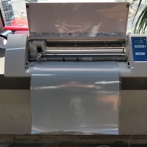
Vinyl Cutter
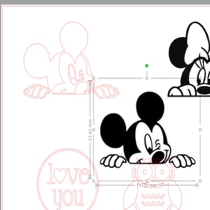
The machine used in our fablab is the Silhouette Cameo printer which comes together with a software in which you have to install in order to edit your images before printing. We decided to create stickers using the vinyl cutter. Images were chosen from google to print and then imported into the software. The software also has images in the library in which you can choose or test out before printing your desired image.
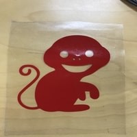
Below are google images I used for printing my stickers.

Here are the links of where I found the images.
Steps on how to use the Silhouette machine
- Choose image from library or import any image you want. To import, go to File>Open.
- Adjust the size of the image by dragging its sides.
-
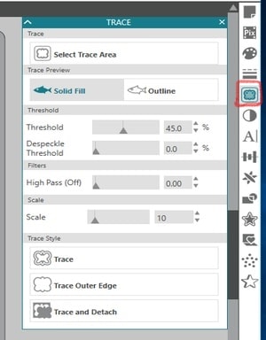
Select the Trace icon to start tracing the image outline (shown below). Adjust the settings as per your preference. Once the image is completely outlined by the yellow, it is ready to get printed.
-
Move the image by dragging it else where to see the trace that has been created. Delete the image once satisfied and just keep the trace.
-
Once you are ready to print, click Send and make sure the printing settings are right. Do not click the final send until the material is loaded onto the machine.
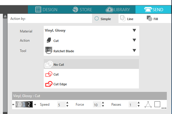
-
Place the vinyl sheet onto the mat provided by the silhouette machine properly.
- Adjust it onto the printer and click on ‘Load cut mat’.
- Then, click on ‘Load media’ to upload the image.
- Finally, click send and the machine will automatically start cutting.
- Once it finished cutting, click on unload.
Steps on transferring the sticker
-
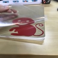
Cut a vinyl transfer sheet which is the size of the sticker.
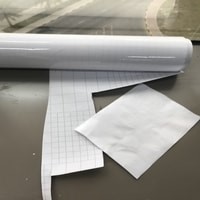
-
Stick it on the sticker to ensure all parts will be removed at once.

-
Slowly remove the parts of the sticker that you do not require.
-
Ensure all parts you want is in the sticker.
-
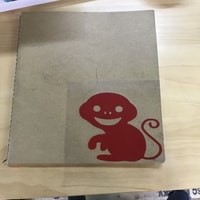
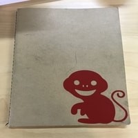
Stick the vinyl trasferring sheet onto any surface you want the sticker to be. Here I stuck it on a book.
-
Remove the transferring sheet slowy and ensure all parts of sticker are stuck onto the surface.
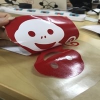
-
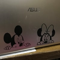
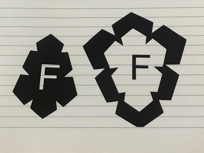
And there’s your sticker! The same procedure was repeated for the other stickers, instead, this time I stuck them on the laptop.
Another design was randomly made in the silhouette software as well.
-
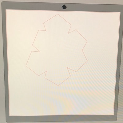
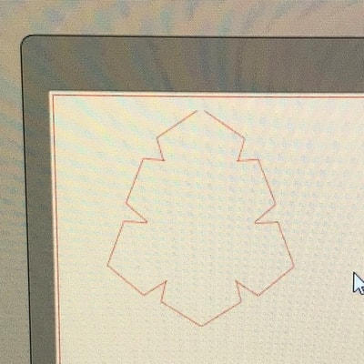
I drew pentagons all over the page.

-
I trimmed the inside lines to create this outline design.
-
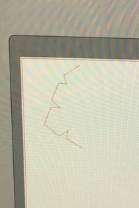
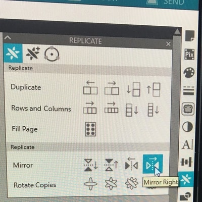
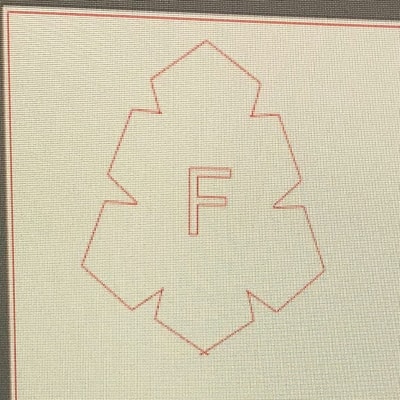
I erased one half of the design to make it symmetric by mirroring it.
-
I added the letter F in the centre.
-
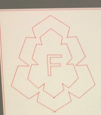
This is the final design.
Laser Cutting
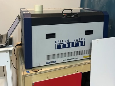
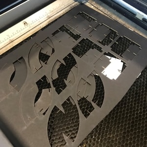
This is the laser cutting machine that we have.
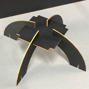
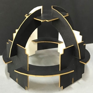
To laser cut, a parametric pressfit kit should be designed. I started my research by finding a suitable design which is made of minimum units but can have numerous shapes made out of it. Many designs found were fixed, which means, they have several different units to make one end product. I found a design online which is made up of two units and can have upto six shapes. Here is a link to the kit in which all six end results will be shown.
In order to do the units, I used solidworks to design it. The pictures below will show the dimensions.
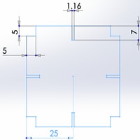
I just used the line tool to create the parameters of the shape and then set the equal constraints to the lines that I want them to be equal. Finally, I defined the dimensions for one side and automatically the other side changed.
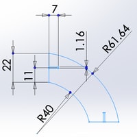
In here, I also used the line in addition to the 2 point arc tool to create the shape. I also used the equal constraint between the dimensions and defined the entire shape.
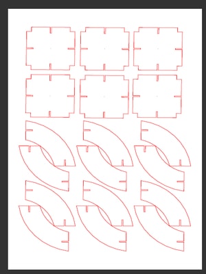
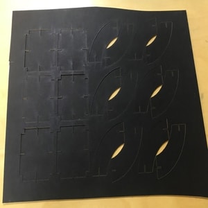
I then exported the file to .DXF and edited it in Inkscape according to my requirements. The printing settings were set the same as the kerfing settings since the pressfit was printed on matboard, except, the matboard dimensions were changed.


Group Assignment
Vinyl Cutter
-
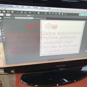
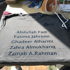
The design was created in the silhoutte studio.
-
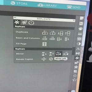
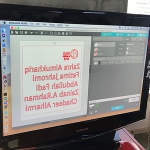
We mirrored the design in order to print in the proper manner onto the tshirt. The printing settings were the same as the previous one since its the same material (vinyl).
-
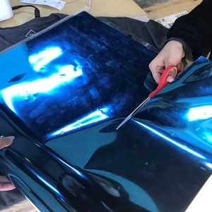
The material was cut in reference to the mat size.
-
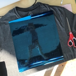
Flip the material by placing the colour that you desire at the bottom in order to get printed onto the tshirt, then, place it on the mat. This is why we mirrored the design.
-
Design after printing.
-
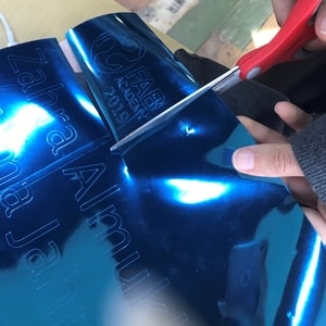
Cut the parts separately.
-
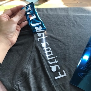
Remove the unwanted parts.
-
Place it onto the area you desire.

-
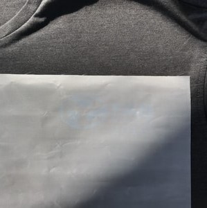
Place a cloth on top of it to prevent direct contact with heat.
-
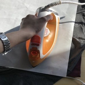
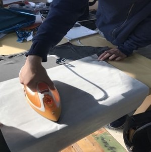
Place the ironing device on top of the design by applying slight pressure to heat it up, which allows the sticker to stick on the shirt. We kept the ironing for 3-4 minutes on the wool temperature.
-
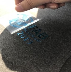
Remove the plastic slowly.

-
End result.
Laser Cutting
Laser cut preparations
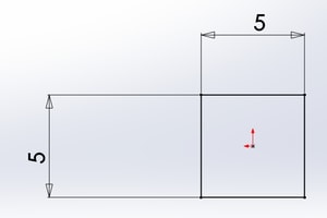
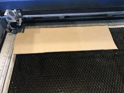
Before laser cutting, we did trials to check the accuracy of the laser cut machine. This is to ensure the difference in measurement when given instructions for cutting and the results after cutting. Two kerfing were made, two squares were drawn in a CAD software, I used solidworks and my colleague used openSCAD. One square had a length of 5 cm and other had 2 cm.
The solidworks file was then exported to .DXF in order to prepare it for laser cutting. The following printing settings were made depending on the material used for laser cutting and the type of cutting (whether cut through or engraving). For kerfing, cut through was made in order to distinguish the measurement difference before and after cutting.
The .DXF file was then opened in Inkscape to edit it.
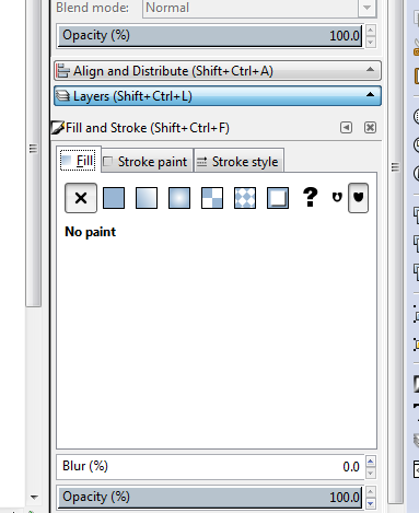
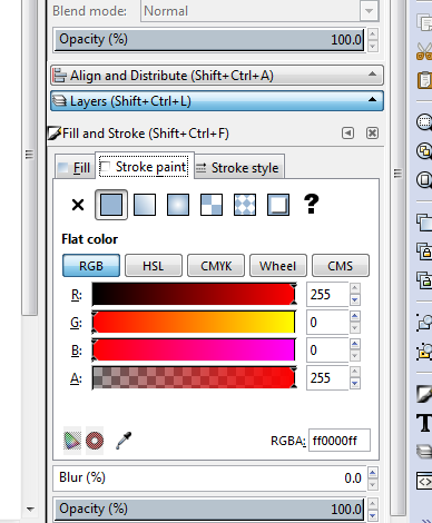
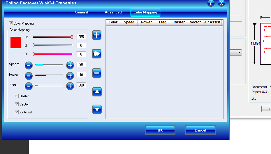
The printing settings were made by colour coding in which the colour red means that the laser cut should do a cut through for the object. Therefore, the picture above shows the colour code for red as 255 and the rest as 0.
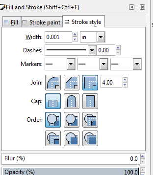
The width should be 0.001 in inches.
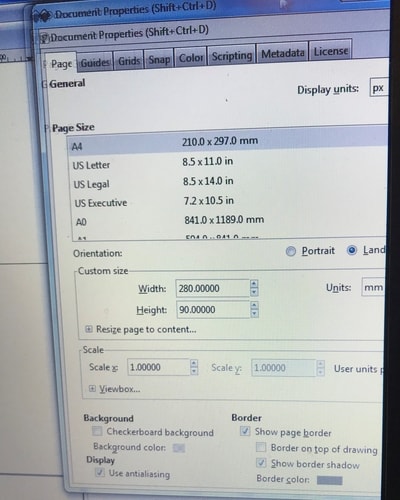
In the custom size section, make sure that the width and height is the exact measurements of the material that you will be insterting into the laser cut machine. The second image shows that the matboard measurements are 28 cm in width and 9 cm in height. Therefore, these measurements are typed in into the custom size as 280 mm and 90 mm.
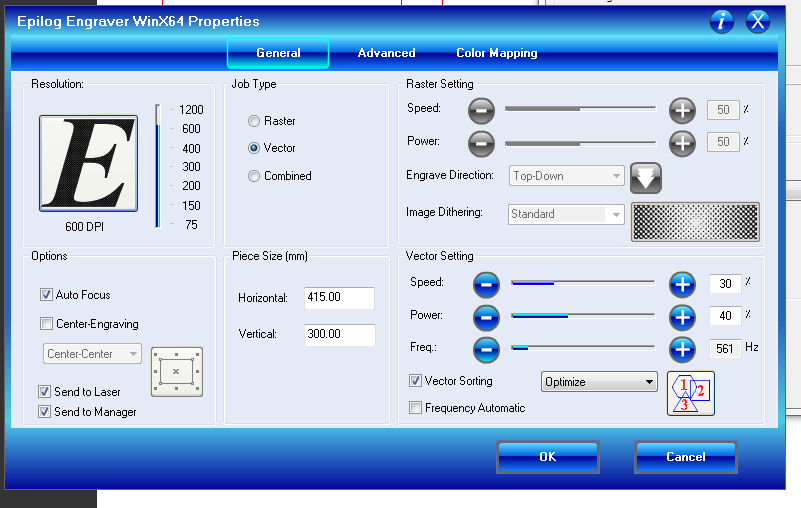
Once editing is done, I saved it as a PDF file since the laser cut machine reads accurately for PDF files. I then opened the PDF, File>Print and the printing settings window popped out. Click on Properties and the window will appear as shown above. These are the settings required for laser cutting a matboard depending on the Epilog laser job manager.
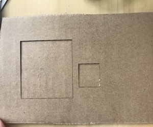
Final result of kerfing.
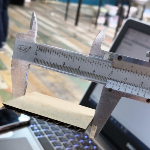
Measurements after laser cutting showed that the sample square had dimensions of 4.9 cm instead of 5 cm and 1.9 cm instead of 2 cm. This means that it gets decreased by 1 mm after cutting.
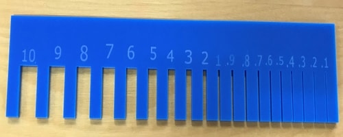
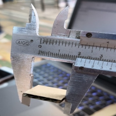
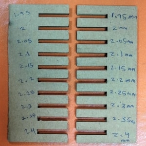
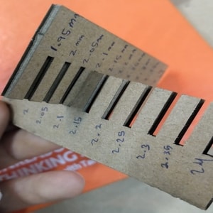
A comb with different teeth sizes was also designed as part of the laser cut preparations to check which fitting will be the most suitable for the specific material. Two of my colleagues decided to design the comb on different materials. One comb was made for matboard with a thickness of 2 mm and the other was comb created for acrylic with a thickness of 3 mm.
Matboard comb
Acrylic comb