5. Electronics production
This Weeks’ Task:
Group Assignment
- Characterise the design rules for your PCB production process.
Individual Assignment
- Make an in-circuit programmer by milling the PCB, program it, then optionally try other PCB processes.
Group Assignment
Here is a link to the group assignment page.
Individual Assignment
Solder practice
I first tried to practice soldering since i have not done it for a while. I practiced on ANDY’s circuit.
Here is a video of how I got started.
At the beginning, I used flux; which looks like a marker; and placed it on top of the area onto which I will solder the component. The flux helps the solder to stick onto the board.
Then, I added a small amout of solder and grabbed the component with the aid of the tweezer. Ensure the tweezers are sharp since it will be difficult to pick up the components.
Simultaneously, place the component on the area onto which it will get soldered to and run the solder on the ends of the components. Check if the soldering has been done properly by visualising the component. The component should be kept flat onto the board.
Here is a video of how I desoldered.
There are several ways of desoldering but here I used the copper braid to desolder. I kept the braid on the solder and applied the solder iron on top of the braid. The heat from the iron will cause the copper to suck up the excess solder and stick onto it. This will remove the unwanted solder.
Building the circuit
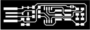
After practicing, I moved on to BRIAN’s circuit since the requirement of this weeks task is to program his circuit. The first step was to mill the PCB. The below circuit images were used.
This is used to mill the tracks
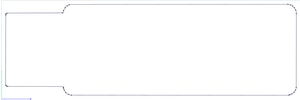
This is used to cut the outline of the circuit.

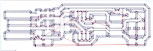
The images prepared before milling.
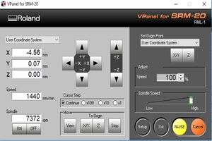
The VPanel was then used to adjust the settings before cutting. The X,Y,Z origins should be identified. This depends on the area you want the end mill to cut on the board. It can be easily adjusted by the clicking the arrows on the panel. For Z origin, use the cursor step option to move the end mill in your preferred step. Ensure that the end mill doesnot hit the surface hard since it will break. Once the origin is defined, click the X/Y and Z buttons placed under the Set Origin Point section. The speed should also be adjusted. Referring to the instructions page for milling the circuits, it was given to use at a speed of 3/4 for the tracks and 0.5 for the outline cut. Lastly, set the spindle speed as medium and click on cut.
Here is a video of milling the PCB.
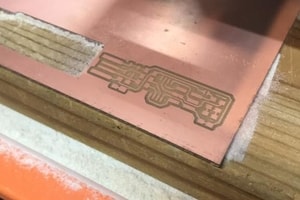
PCB after milling was done.
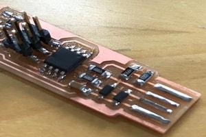
Assembling the PCB
This is how the PCB looks after soldering BRIAN’s circuit. I referred to his page for soldering his circuit.
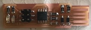
Bridge was created in order to program the ATtiny45 micro-controller.
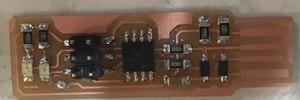
Improving the USB connector
Solder was added onto the tracks of the USB in order to detect once connected to the cable. This was done to add a layer on the track since the surface was low and it wasnt able to detect the USB.
Check your work
- Visualise your circuit by checking the components if its laid flat and soldered properly onto the board.
- Try doing the continuity test using a multimeter for your circuit to ensure all connections are made properly.
- Put the circuit into the USB cable after soldering the tracks to check whether it will get detected by the computer or not.
Software installation
Before starting to program the ATtiny45, you should download the software. You can refer to BRIAN’s page, scroll down to the software installation section and download the one suitable for you.
After installing the software, the first thing you have to do is create a new folder of your own in order to place all your downloaded files here. Download the firmware source code into your folder from his page as well, and unzip the file in your terminal by typing unzip fts_firmware_bdm_v1.zip and then make to build the file that will help you program the ATtiny45. This step will be shown in the first two lines of the command lines below.

Program the ATtiny45
-
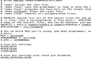
Update the type of programmer that you are going to use to program the ATtiny45. To do this, you have to edit the file called ‘Makefile’ in your folder. Open the file, in the ‘PROGRAMMER ?= usbtiny’ line, replace the ‘usbtiny’ by the type of programmer that you are using. In my case, the programmer I used was avrisp2. You can refer to BRIAN’s page to know the type of your programmer.
-
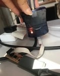
Plug the circuit board into a USB port and connect the programmer to the header. Ensure that you connect the programmer correctly with the header since it has two different orientations of connecting it. If the green light in the programmer lights up, then your connection is right. If not, an orange light will light up. Then type in
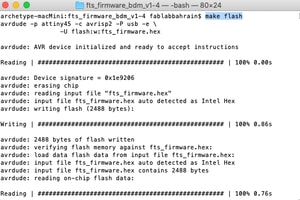
make flashin your terminal. This will erase the target chip, and program its flash memory with the contents of the .hex file you built before. You should see several progress bars while avrdude erases, programs, and verifies the chip.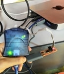
-
Type in
make fusesin your terminal. This will set up all of the fuses except the one that disables the reset pin.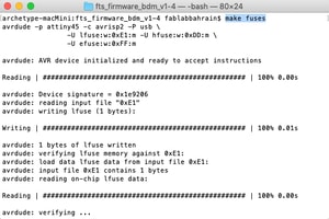
-
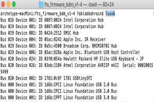
To ensure whether the USB port is reading the board, you have to check whether it appears in your system. You can find different methods in BRIAN’s page for different OS to check if the USB works. In my case, this is how I checked. I typed in
lsusbin the terminal to list all the usb devices that are connected to the system. If the programmer name appears, then its connected.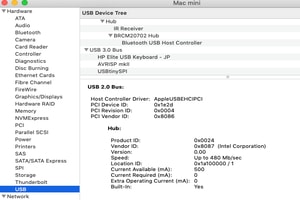
-
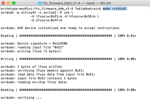
The last step is to type
make rstdisblin your terminal. This does the same thing as the make fuses command, but this time it’s going to include that reset disable bit as well.