3. Computer Aided design (CAD)
This Weeks’ Task:
- Model (raster, vector, 2D, 3D, render, animate, simulate, …) a possible final project.
Design Research
My final project will be about designing a mug coaster that will allow heat to transfer through it and into the mug. Since I have not thought of a specific design for my coaster, I started reaserching about possible designs that will be suitable for the coaster. As a start, I thought of designing the usual standard mug coasters using different CAD softwares and then updating the design as I gradually proceed with the course. Therefore, I found a video which helped me get started in designing the coaster clearly and professionally.
Initially, I started my design with a simple 2D model and renovated it using 3D softwares. Detailed procedure of the coaster design will be shown clearly, in addition to the different softwares used as well as the link to where i have downloaded them.
In addition to the research, a two day workshop about parametric design and laser cutting was prepared by our FabLab. The first workshop was held on Friday 1st February and the second workshop will be held on Saturday 9th February. The workshop included an introduction to Rhino and how to design using parametric design. At the end of the workshop, each student should be able to design and use the laser cuter to cut the design.
2D Modelling
Raster - GIMP
Below are some links that helped me in designing my 2D model
Steps on designing my model
-
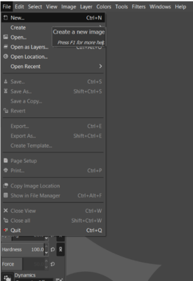
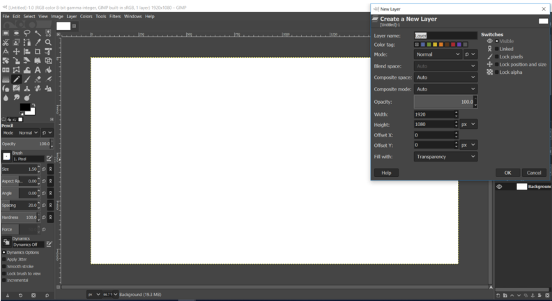
Open gimp. The first step before designing anything is to create a new image. Go to File>New as shown below.
-
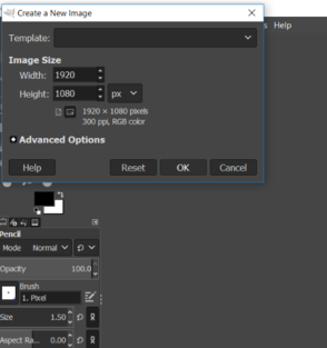
A window will pop up. Set the options as default and click OK.
-
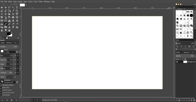
After clicking OK, a white blank page will appear, which will be used for sketching.
-
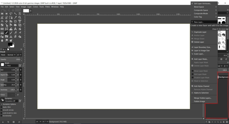
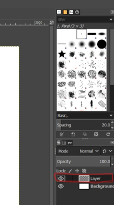
Before starting to sketch, a layer should be created. Right click on the panel highlighted by red and select New layer.
-
A window will pop up. Set the options as default and click OK.
-
A layer will then be created.
-
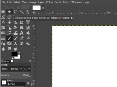
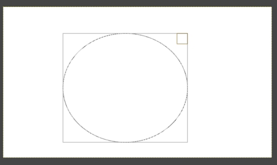
In the toolbox on the top left corner, choose the appropriate tools that you require for your drawing. I selected the eclipse tool since I want to draw a circle.
-
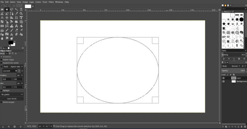
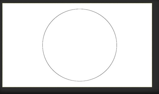
Click and drag on the blank page to draw the circle.
-
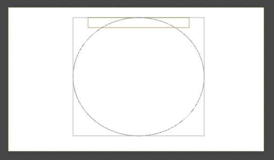
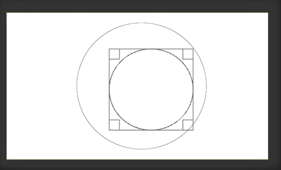
Adjust your shape by hovering your mouse on the rectangle edges surrounding your shape.
-
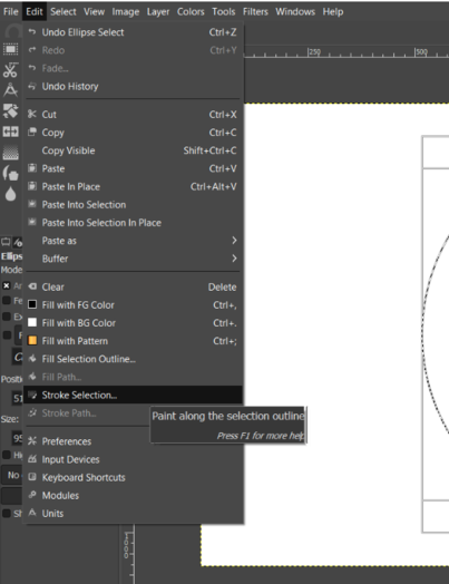
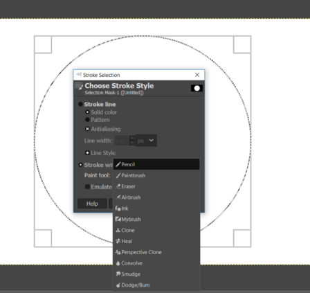
Next, go to Edit>Stroke Selection to fix the shape you have drawn into the page.
-
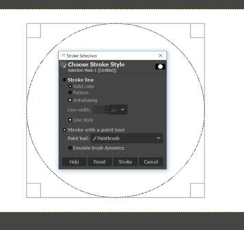
A window will pop up looking similar to the one below.
-
Under the ‘Stroke with a paint tool’ heading, select the paint tool as per preference. In my case, a chose pencil for my sketch.
-
The sketch will then be fixed onto the page.
-
I then repeated the same procedure again to sketch a smaller circle inside my first circle.
-
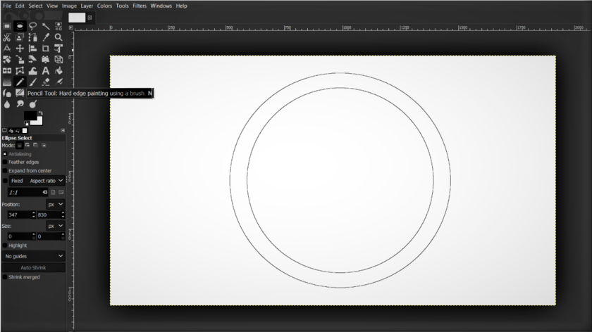
To change the size of your tool. Go to the toolbox and click on the tool you are using. In this example, I clicked on the pencil tool.
-
After clicking, the settings will be shown below the toolbox in which you will be able to edit the size and thickness of the tool.
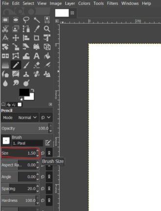
-
Four half circle shaped were drawn in between the circles to represent the round edge of the coaster.
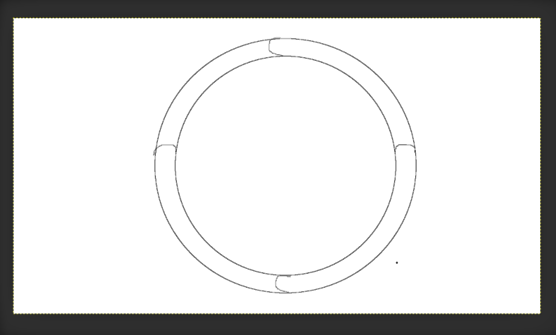
-
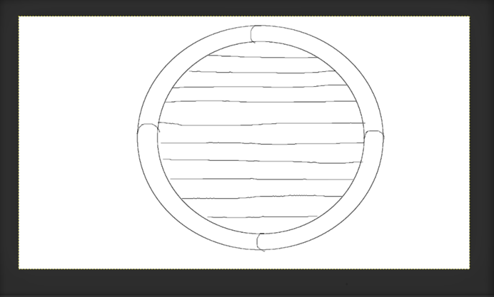
Thin horizontal lines were drawn in the smaller circle to represent the thin surface at the centre of the coaster that allows faster heat transfer.
Vector - Free CAD
I used the tutorial that has been provided by the FabAcademy itself to get familiarised with Free CAD. Here is a link to the video.
Steps on designing my model
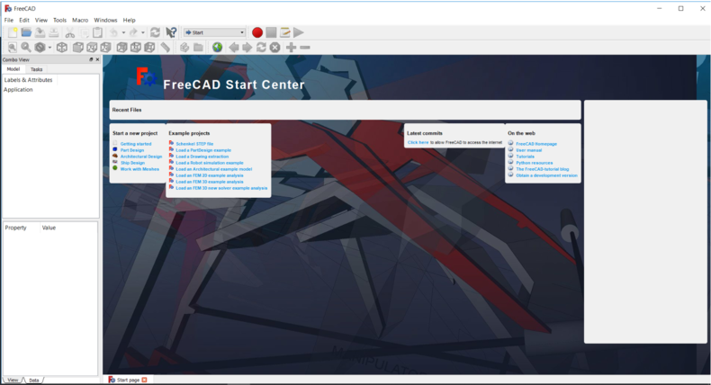
-
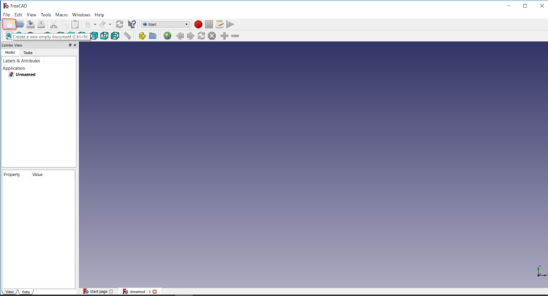
Open Free CAD. A page similar to the one below should appear up.
-
To start a new project, go to File>New or just click on the new page icon found on the top left corner highlighted in red in the image below.
-
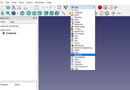
To start sketching, click on the drop down box shown below and select Sketcher.
-
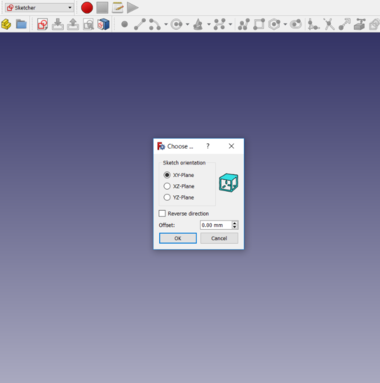
A window should pop up in order to select the plane you want to sketch in.
-
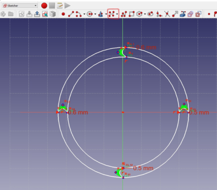
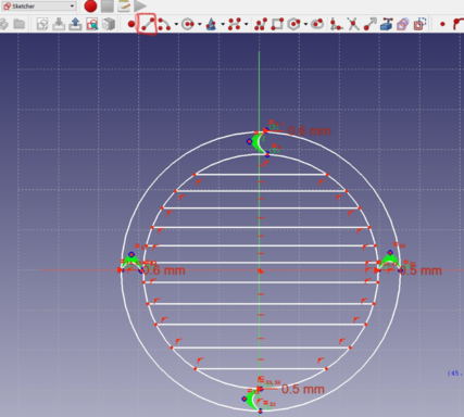
In the toolbar above, select the shape you want to draw. Click on a point in the page and move your mouse to define the size of the shape. In this case, I chose the circle which is highlighted in the image below.

-
To draw the half circle shapes, I used the B-spline tool also highlighted in red.
-
To draw the lines in the centre, I used the line tool highlighted in red.
3D Modelling
Tinkercad
Before beginning, I created an account in tinkercad and then started with the design. Working with tinkercad was easy and I didn’t find any difficulty at all since everything was clear. I just had to click on items and discover how to move things around and edit them.
I wanted to start with something very simple and basic to help me understand how tinkercad works.
Steps on designing my model
-
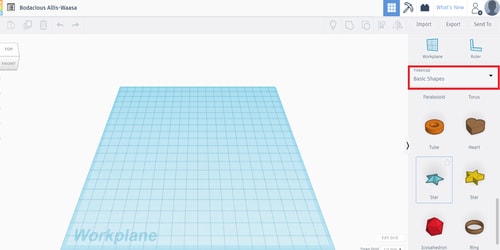
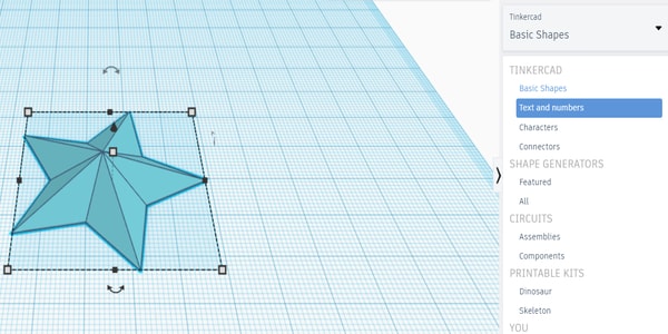
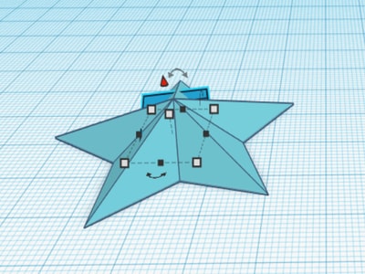
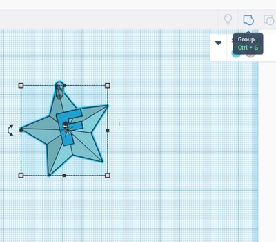
On the right, there will be a design toolbar where you can choose the items that you want to create. In addition, there will also be a ‘Tinkercad’ drop down list where you can choose your categories and start design your model. I started off by choosing a star and dragging it onto my workplane.
-
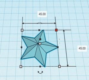
I then clicked on the object and moved my cursor to any of the four corners, where the dimension lines appeared. I clicked on the numbers and changed by dimensions to 45 mm as shown. You can also use the arrow at the bottom centre of the object to help you in rotating the model.
-
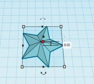
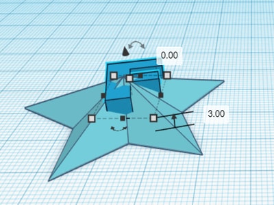
I clicked on the centre point shown in red to show the height dimension of the model. Click on the number and change it to your desired height.
-
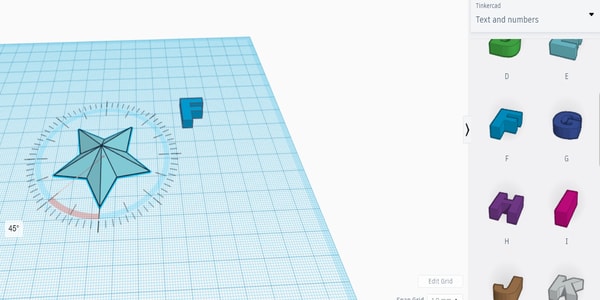
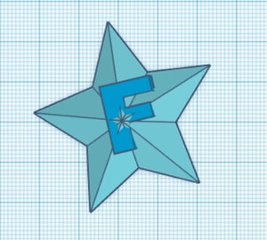
To explore more in tinkercad, I went to the drop down list and discover the things that are available there. I selected the text and numbers and chose my letter “F” to place it on the star. I also tried rotating the model to see how it works. I just dragged the pointer in the circular labelling shown and the object rotated.
-
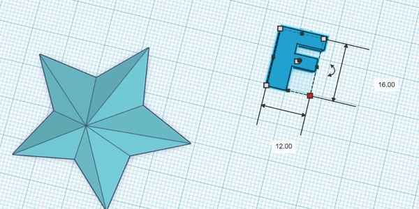
I repeated the same procedures to change the dimensions of the letter.
-
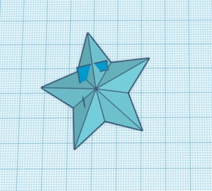
I dragged the letter so that I can place it in the centre of the star.
-
To raise the letter above the workplane, click on the object itself, then click on the red cone shaped point that appears on top of the object. Drag this point upwards or change the number manually to raise it up. I only raised it by 3 mm above the plane to make it consistent the design.
-
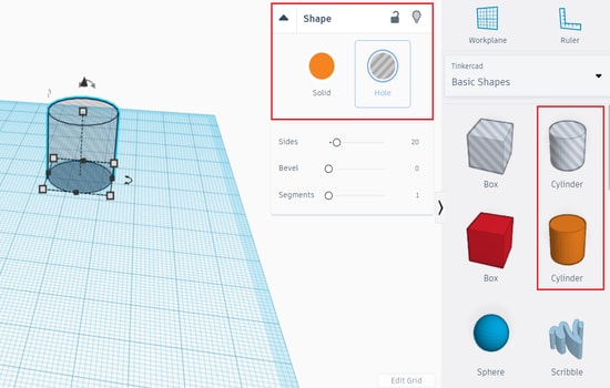
I then wanted to create a hole at the top so that I can hang it somewhere or have it as a key chain, therefore, I chose a cylinder to create it. I can either choose a ready hollow cylinder from the basic shapes, or choose a solid cylinder and then change its properties to hole whenever I want to.
-
I placed the cylinder in the position where I want my hole to be.
-
I then grouped the 3 shapes together by holding the ‘shift’ button and selecting the objects one at a time, or right click and drag the pointer on the model and all 3 shapes get selected at once. After selecting, click on the group/ungroup icon placed at the top as shown in the image.
Here is a link to my design.
Solidworks
Solidworks is a familiar software to me since i have been taught to use it in the university. Therefore, I chose it for designing my project model.
Steps on designing my model
-
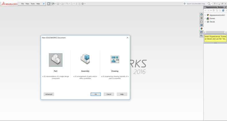
Open solidworks. The first step before designing anything is to create a new file. You can either go to File>New>Part or just click on the page icon next to the toolbar and select part.
-
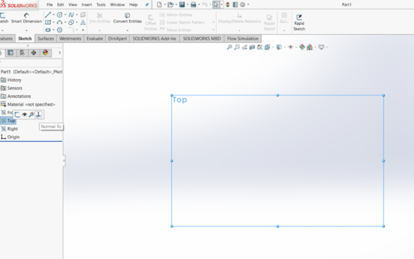
Before drawing, you should select the plane that you prefer drawing in. Click on the plane and select Normal To.
-
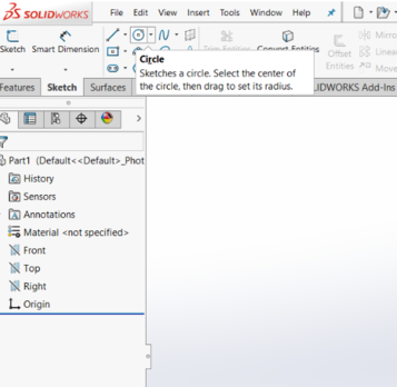
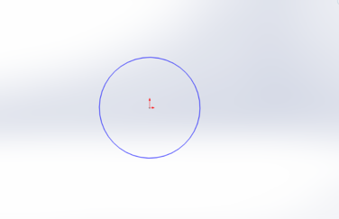
From the Sketch toolbar, click on the shape you want to draw. Click on the sketch area to start drawing and move your mouse to define the size of the shape.
-
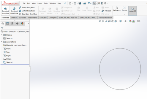
Exit the sketch and go to the Features toolbar in order to start 3D modelling your shape. Click on Extrude Boss/Base which is found on the top left corner.
-
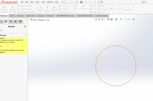
Select the plane onto which the sketch has been drawn or just click on the shape itself.
-
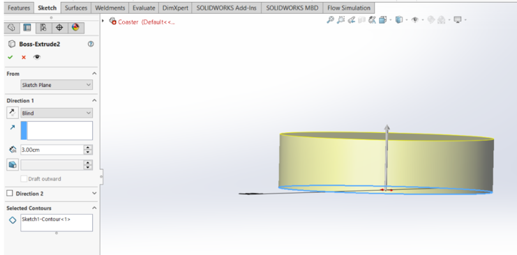
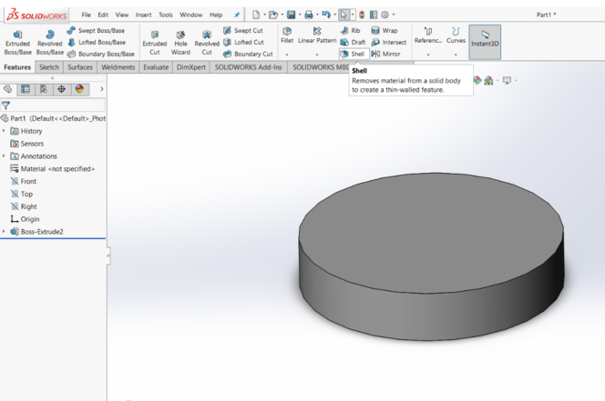
The settings will appear in which you will have to input your required data. In my case, I wanted to define the height of the coaster to be as 3 cm. Therefore, I have typed 3 cm in the selection box. The datas that I am inputing at this stage will be changed depending on the electronic components and circuit boards. Click on the tick mark once you`re done.
-
The model will then be created. Since I wanted my model to be hollow, I used the shell feature which can be found from the Features toolbar.
-
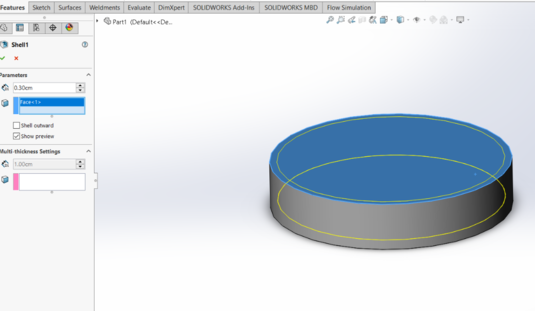
Then, in the settings window, I chose my model’s thickness to be 0.3cm ~ 3mm followed by the face that I want it to get removed. You can tick the Show preview box to see how the model will look like. The yellow line below shows the preview.
-
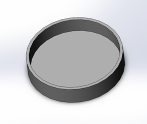
This is how the model will look like after using the shell feature.
-
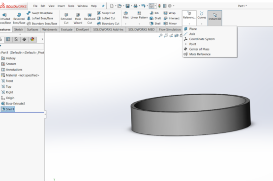
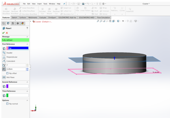
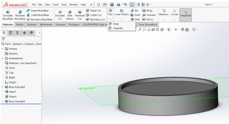
In order to create a custom plane, go to Features>Reference Geometry>Plane.
-
In the settings window, you have to select a plane/edge/face onto which the new plane will have to be referenced. In my case, I referenced it to the top plane. Then, I inputed the distance that the new plane will be from the referenced plane. The distance here is 2.2 cm.
-
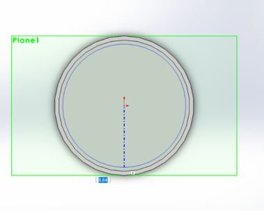
Click on the new plane formed ‘Plane 1’ and select Normal To in order to start sketching. I have drawn a smaller circle here.
-
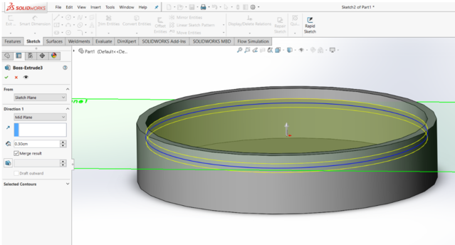
After drawing, the same procedure has been repeated and extruded the sketch. Here, I have extruded it to 0.3 cm. This surface will have the mug placed on it. Thereofore, it should be as thin as possible to allow faster heat transfer.
-
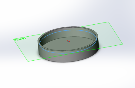
This is how the product will look from the inside. The hollow part at the bottom is where all the electronic components will be placed. The space above the contact surface is an indent to trap any liquid when fallen. This is to prevent the liquid from touching any tables or creating a mess.
-
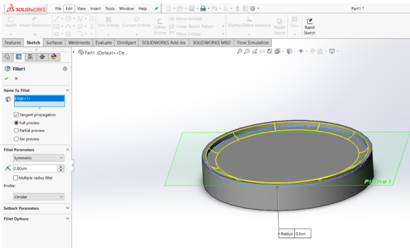
In order to remove any sharp edges, fillet will have to be done. The fillet option can be found in the features toolbar.
-
I selected the edge where I want to fillet and chose the fillet radius to be as 0.8 cm.
-
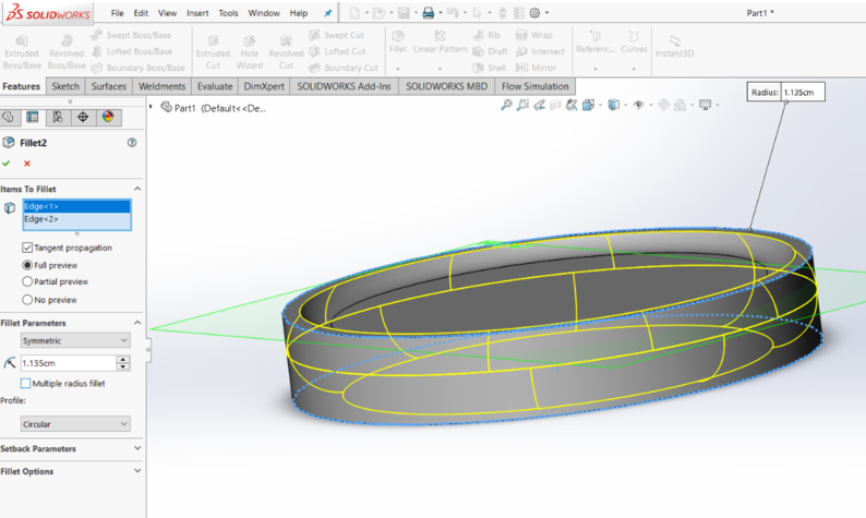
The fillet feature was again opened to select another edge with a different radius. In this case, the top and bottom edges were selected and the radius was given to be 1.135 cm. This was to create a circular edge for the coaster.
-
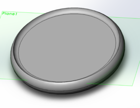
The product after using fillet feature.
-
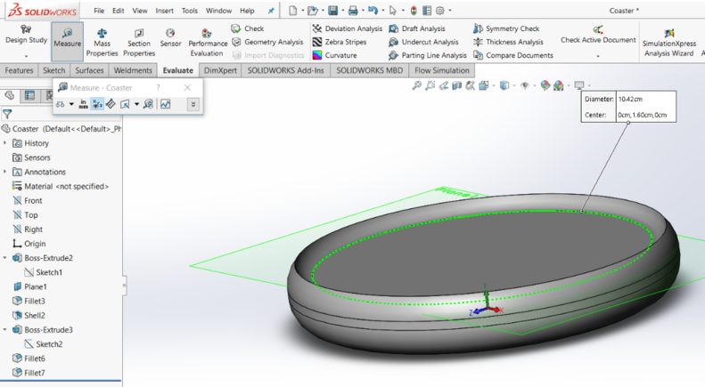
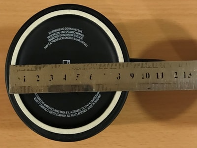
To measure something, go to Evaluate toolbar>Measure and click on the edge where you want to measure. This step was done to ensure that the inner radius of the coaster is not less than 8.5 cm. This is a reference to the mug measured at home as shown below.
-
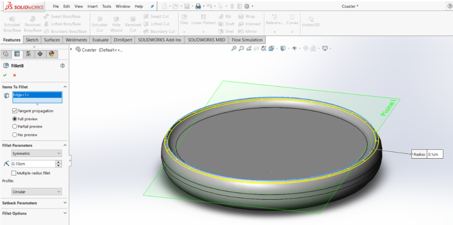
The fillet feature was again used to remove the sharp edge at the top. A radius of 0.1 cm was given.
-
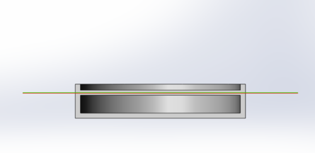
These are the front and top view of the coaster
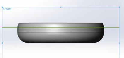
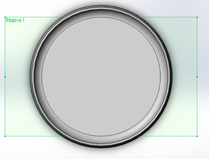
-
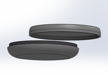
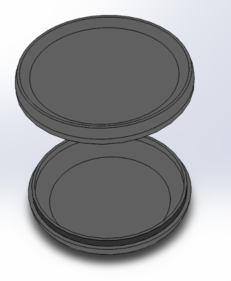
An assembly of my mug coaster to show how it will fit together.
I exported my solidworks part file to .stl in order to upload it on sketchfab since i found difficulty uploading it directly to sketchfab.