9. Embedded programming
This Weeks’ Task:
Group assignment
- Compare the performance and development workflows for other architectures.
Individual assignment
- Read a microcontroller data sheet.
- Program your board to do something, with as many different programming languages and programming environments as possible.
Group Assignment
Here is a link to the group assignment page.
Individual Assignment
Microcontroller datasheet
Before starting to program my board, the microcontroller that we used for the hello echo world circuit is the ATtiny44, which will be the same circuit that I am going to use in this assignment. Here is a link to the datasheet.
These are some important things to consider about the microcontroller, they are:
- Low-power CMOS 8-bit microcontrollers.
- Ten times faster than conventional CISC microcontrollers.
- Are based on the AVR enhanced RISC architecture.
- Achieves throughputs close to 1 MIPS per MHz.
This is its pin configuration and description:


There are 2 ports in a mircocontroller, Port A and port B. Port A has ADC pins which means they are pins that can read analog and digital signals. This is important since it will make it useful to connect any input or output device to the right pin in the microcontroller. Any component that gives out analog signals should only be connected to port A pins since port B will not be able to read analog signals.
Here is a different pin configuration of the attiny44 used for arduino ide

You can also find more things in the datasheet such as:
- Packaging information about the attiny44 with its dimensions and layout.
- Register summary for programmers.
- Instruction set summary for programmers.
Programming
I used two programming environments for my project, one was Arduino IDE and the other was Atmel Studio. I did the same programming for both which is by using the push button to light up the LED.
Arduino IDE
Programming language: C/C++
I used my usbtiny to program my hello echo world circuit and the image below shows the setup.

In the arduino software, I chose the push button example by going to File>Examples>Digital>Button.
Below will be the example of the code I used. I inserted my LED and button pin numbers as per my schematic of the hello echo world circuit.
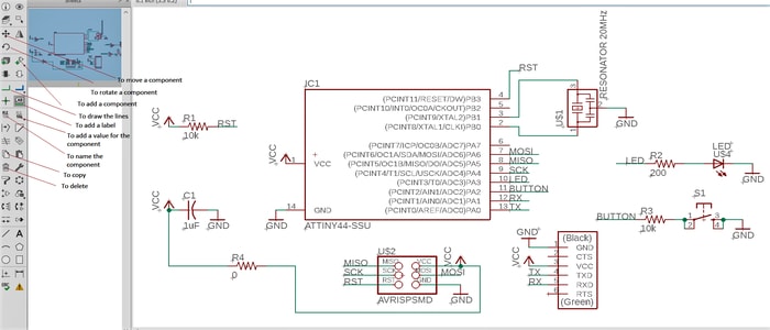
This is my schematic.
Code example
// constants won't change. They're used here to set pin numbers:
const int buttonPin = PA2;     // the number of the pushbutton pin
const int ledPin =  PA3;      // the number of the LED pin

// variables will change:
int buttonState = 0;         // variable for reading the pushbutton status

void setup() {
  // initialize the LED pin as an output:
  pinMode(PA3, OUTPUT);
  // initialize the pushbutton pin as an input:
  pinMode(PA2, INPUT);
}

void loop() {
  // read the state of the pushbutton value:
  buttonState = digitalRead(PA2);

  // check if the pushbutton is pressed. If it is, the buttonState is HIGH:
  if (buttonState == HIGH) {
    // turn LED on:
    digitalWrite(PA3, HIGH);
  } else {
    // turn LED off:
    digitalWrite(PA3, LOW);
  }
}
The settings that I used to program the board.

My circuit did work and the LED light lit up when I pushed the button, however, it was not stable. Whenever I moved the circuit around, it used to light up. Also, if I just touch the button without pressing it, it lights up. After discussing it with my instructor, we found out that my circuit is connected in a different way. As you can see from my schematic, one end of the push button is connected to the microcontroller and the other end to the ground. In general, the push button codes are written in a way to program the push button when the other end is connected to the vcc instead of ground. Therefore, I researched about the input pullup serial which is to invert the code and allow the push button to work while its still connected to the ground. I followed the steps and adjusted the code written on that page. The code example below shows the modified version of the button example. The settings remained the same.
// constants won't change. They're used here to set pin numbers:
const int buttonPin = PA2;     // the number of the pushbutton pin
const int ledPin =  PA3;      // the number of the LED pin

// variables will change:
int buttonState = 0;         // variable for reading the pushbutton status

void setup() {
  // initialize the LED pin as an output:
  pinMode(PA3, OUTPUT);
  // initialize the pushbutton pin as an input:
  pinMode(PA2, INPUT_PULLUP);
}

void loop() {
  // read the state of the pushbutton value:
  buttonState = digitalRead(buttonPin);

  // check if the pushbutton is pressed. If it is, the buttonState is HIGH:
  if (buttonState == HIGH) {
    // turn LED on:
    digitalWrite(PA3, LOW);
  } else {
    // turn LED off:
    digitalWrite(PA3, HIGH);
  }
}
Atmel Studio
Programming language: C
-
Open Atmel Studio > New Project > click on GCC C Executable Project > choose the name and location > OK.
.jpg)
-
In the Device Selection window, Choose the device family ATtiny > ATtiny44 > OK.

-
Delete the code example and type in your code.
``` #define F_CPU 20000000 // AVR clock frequency in Hz, used by util/delay.h #include <avr/io.h> #include <util/delay.h> int main() { DDRA |= (1<<PA7); // set LED pin to output while (1) { PORTA |= (1<<PA7); // LED high _delay_ms(500); // delay 500 ms PORTA &= ~(1<<PA7); // LED low _delay_ms(1000); // delay 1 s } } ``` -
Click on build solution or press F7 to get the output.

-
Click on tools > device programming and change the settings as shown below.

-
The LED should be blinking now.