17. Machine Design (May 22)
This week we were suggested:
For the Group assignment:
Group assignment
- Actuate and automate your machine.
- Document the group project
For the Individual assignment:
- Document your individual contribution.
Actuation of the xy plotter
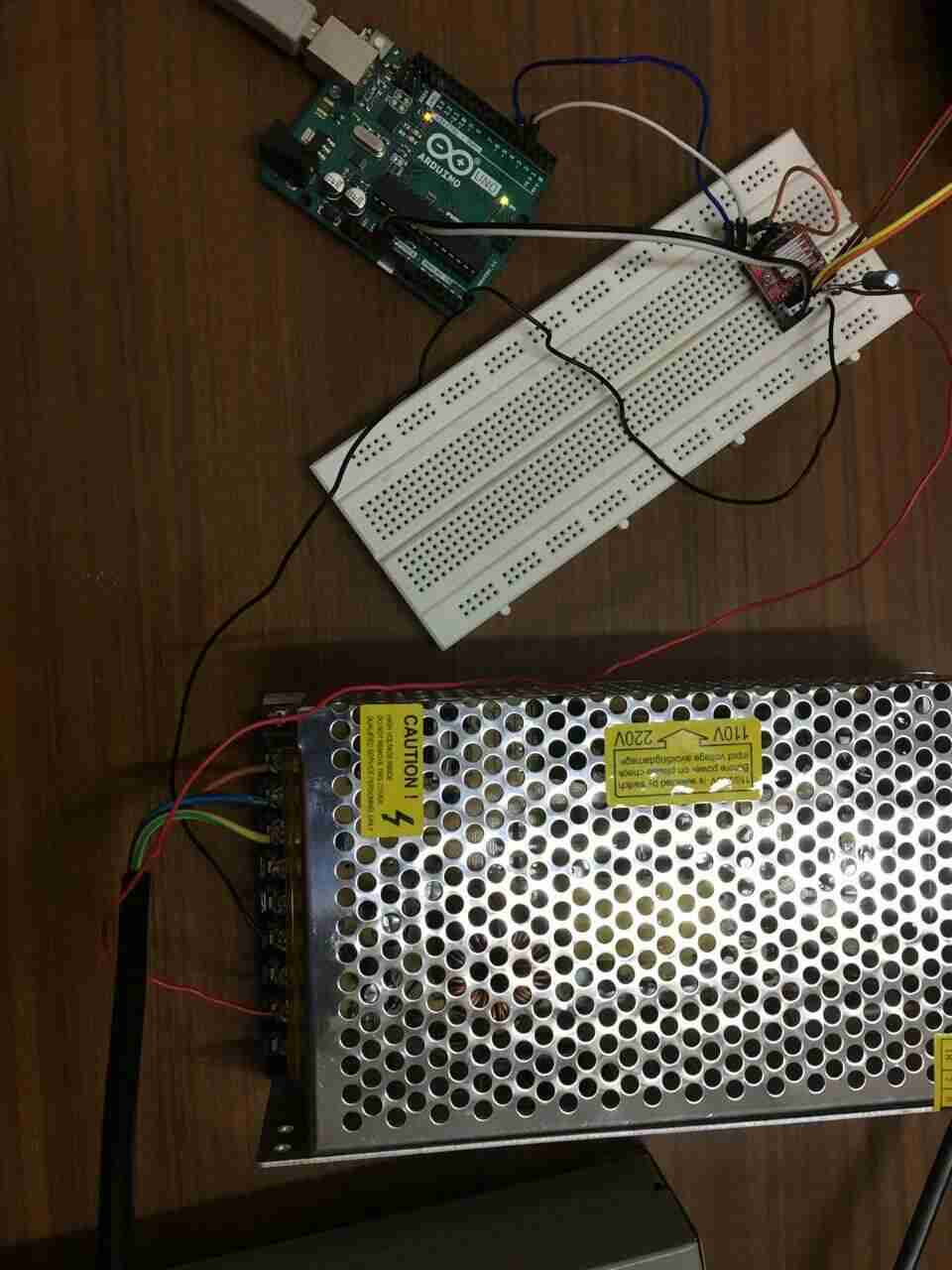
The first step was to test each stepper motor, limit switch and servo motor to find out if they worked. I used arduino code to verify the actuation. Arduino Uno was connected to A4988 motor driver and the stepper motor for this purpose.
The code used in arduino IDE for actuating the stepper motors was:
/*     Simple Stepper Motor Control Exaple Code
 *    https://howtomechatronics.com/tutorials/arduino/how-to-control-stepper-motor-with-a4988-driver-and-arduino/
 *  by Dejan Nedelkovski, www.HowToMechatronics.com
 *
 */
// defines pins numbers
const int stepPin = 3;
const int dirPin = 4;

void setup() {
  // Sets the two pins as Outputs
  pinMode(stepPin,OUTPUT);
  pinMode(dirPin,OUTPUT);
}
void loop() {
  digitalWrite(dirPin,HIGH); // Enables the motor to move in a particular direction
  // Makes 200 pulses for making one full cycle rotation
  for(int x = 0; x < 200; x++) {
    digitalWrite(stepPin,HIGH);
    delayMicroseconds(500);
    digitalWrite(stepPin,LOW);
    delayMicroseconds(500);
  }
  delay(1000); // One second delay

  digitalWrite(dirPin,LOW); //Changes the rotations direction
  // Makes 400 pulses for making two full cycle rotation
  for(int x = 0; x < 200; x++) {
    digitalWrite(stepPin,HIGH);
    delayMicroseconds(500);
    digitalWrite(stepPin,LOW);
    delayMicroseconds(500);
  }
  delay(1000);
The x axis actuation was succesfully implemented. The demo video:
The x axis actuation tested the use of timing belts with pulleys. This was a eureka moment for me to find the mechanism working in the first go. I did reduce the slackness in the mechanism after few trials.
The y axis actuation was succesfully implemented as follows:
The z axis actuation was succesfully implemented as follows:
This tested the use of lead screw mechanism in the z axis.
The code used in arduino IDE for testing the limit switch was:
// defines pins numbers
http://www.arduinotutorialonline.com/2018/01/stepper-motor-with-limit-switch-arduino.html
const int limitPin = 7;

void setup() {

  pinMode(limitPin,INPUT);
    // initialize digital pin LED_BUILTIN as an output.
  pinMode(LED_BUILTIN, OUTPUT);

 digitalWrite(LED_BUILTIN, LOW);

}
void loop() {

 if( digitalRead(limitPin) == HIGH){
  digitalWrite(LED_BUILTIN, HIGH);   // turn the LED on (HIGH is the voltage level)
  delay(100);                       // wait for a second

 }
 else {digitalWrite(LED_BUILTIN, LOW);    // turn the LED off by making the voltage LOW

 delay(100);                       // wait for a second
 }

}
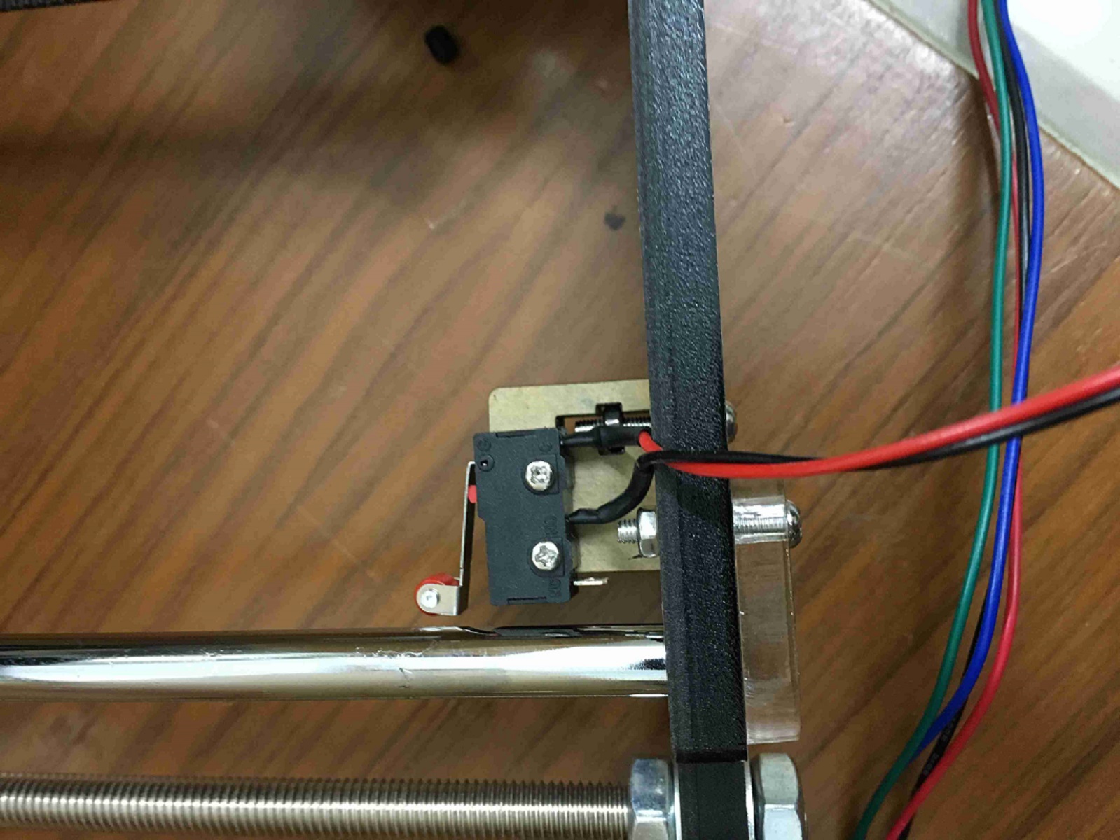
The image shows the limit switch on the machine.
This image shows the test of the limit switch with the led turned on when the limit switch is not pressed.
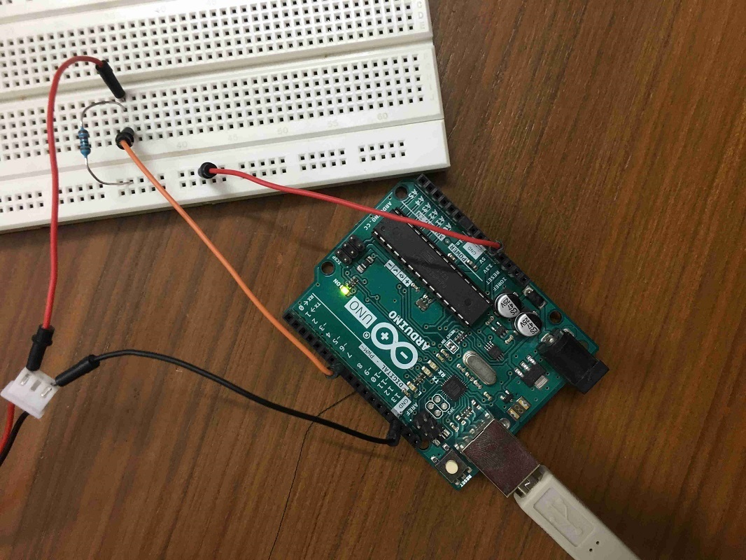
Next, I also tested the servo motor for the pen lift.
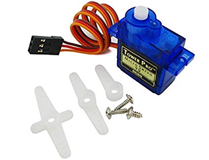
This was the code in Arduino IDE. The connections are pretty simple with one pin each connected to the 5V, ground and pin number 9. When connected to the Arduino, the servo motor went from from its position to 180 degrees and back.
//www.elegoo.com
//2016.12.08
#include <Servo.h>

Servo myservo;  // create servo object to control a servo
// twelve servo objects can be created on most boards

int pos = 0;    // variable to store the servo position

void setup() {
  myservo.attach(9);  // attaches the servo on pin 9 to the servo object
}

void loop() {
  for (pos = 0; pos <= 180; pos += 1) { // goes from 0 degrees to 180 degrees
    // in steps of 1 degree
    myservo.write(pos);              // tell servo to go to position in variable 'pos'
    delay(15);                       // waits 15ms for the servo to reach the position
  }
  for (pos = 180; pos >= 0; pos -= 1) { // goes from 180 degrees to 0 degrees
    myservo.write(pos);              // tell servo to go to position in variable 'pos'
    delay(15);                       // waits 15ms for the servo to reach the position
  }
}
Automation
After getting the confidence with the actuation, it was time for automation. We wanted to be able to create a drawing in a 2D vector software such as Inkscape, then convert this drawing into tool path using a g-code extension for inkscape, followed by sending this gcode to the machine.
GRBL is commonly used firmware with the CNC shield for Arduino for motion control with CNC based operations. So, I was searching for some previous projects using GRBL to automate an xy plotter. I did find this instructable for me to get step by step instructions to build my first machine :).
BOM for automation
The materials required for automation were: 1. Arduino Uno 2. CNC Shield V3 3. Servo motor 4. 2 A4988 motor drivers 5. Pen holder 6. Pen slider mechanism 7. 12 V DC power supply upto 10 A current
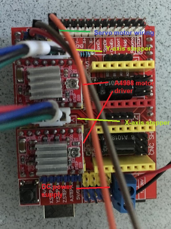
Wiring diagram
This image shows the wiring done on the CNC shield. Before this wiring, the CNC shield was placed over Arduino Uno.
GRBL firmware
Next, the GRBL firmware was downloaded, renamed as GRBL and placed in Arduino libraries folder. The grblUpload.ino example file was uploaded in Arduino Uno.
Image in Inkscape
I wanted to plot the image of sunset so I googled for such images. I chose this image.

Inkscape extension for Servo Motor
Next, please make sure that you have Inkscape version 0.47 as the inkscape extension for servo works only in this version of Inkscape. Inkscape extension was downloaded from this link. Next please download these files in inkscape directory>Share>Extension folder.
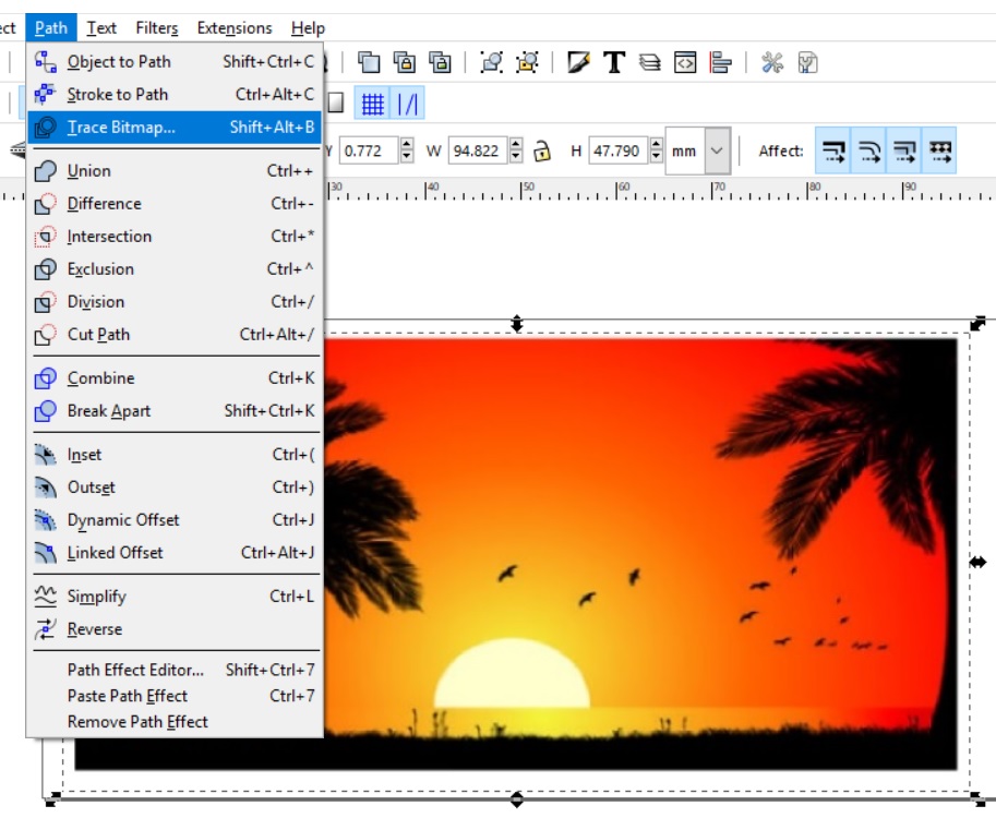
G-code creation in Inkscape
Now open inkscape and set page size to 100 mm x 50 mm from menu icon File>Document Properties.

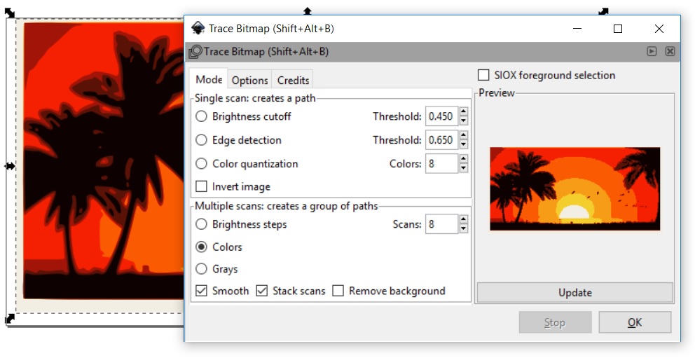
Now we need to vectorize this bitmap using the trace bitmap feature.
The vectorized image with the thresholding results in this image.
This image can be used to generate the tool path and g-code generation using the GRBL extension (MI GRBL Z-AXIS SERVO CONTROL) under the Extensions menu icon. The following image shows the settings used in the extension. Please play with the g-code M4 or M3 depending on which one of these gives the servo the lift.
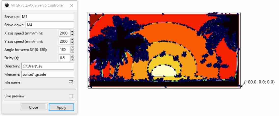
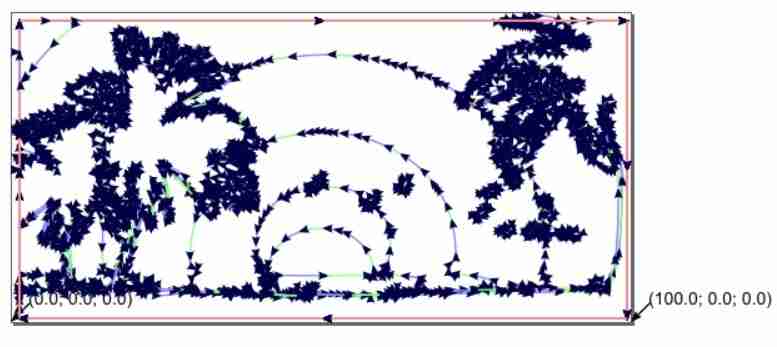
This image separates the actual tool path from the vectorized image. This is what would be sketched by the xy plotter with the help of the g-code created in this file.
G-code streaming software
For streaming the g-code to Arduino, the universal g-code sender was downloaded. Please connect the Arduino to the laptop and open this software. Select the COM port and set the baud rate to 115200. Click on “Open”. Next go to the “Commands” Tab. Enter $$ for knowing the present GRBL configuration.
My GRBL settings:
$0=10 (step pulse, usec)

$1=25 (step idle delay, msec)

$2=0 (step port invert mask:00000000)

$3=0 (dir port invert mask:00000000)

$4=0 (step enable invert, bool)

$5=0 (limit pins invert, bool)

$6=0 (probe pin invert, bool)

$10=3 (status report mask:00000011)

$11=0.010 (junction deviation, mm)

$12=0.002 (arc tolerance, mm)

$13=0 (report inches, bool)

$20=0 (soft limits, bool)

$21=0 (hard limits, bool)

$22=0 (homing cycle, bool)

$23=0 (homing dir invert mask:00000000)

$24=25.000 (homing feed, mm/min)

$25=500.000 (homing seek, mm/min)

$26=250 (homing debounce, msec)

$27=1.000 (homing pull-off, mm)

$100=5.000 (x, step/mm)

$101=5.000 (y, step/mm)

$102=100.000 (z, step/mm)

$110=500.000 (x max rate, mm/min)

$111=500.000 (y max rate, mm/min)

$112=500.000 (z max rate, mm/min)

$120=10.000 (x accel, mm/sec^2)

$121=10.000 (y accel, mm/sec^2)

$122=10.000 (z accel, mm/sec^2)

$130=40.000 (x max travel, mm)

$131=40.000 (y max travel, mm)

$132=200.000 (z max travel, mm)
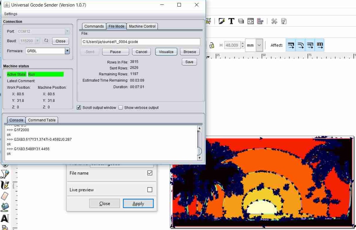
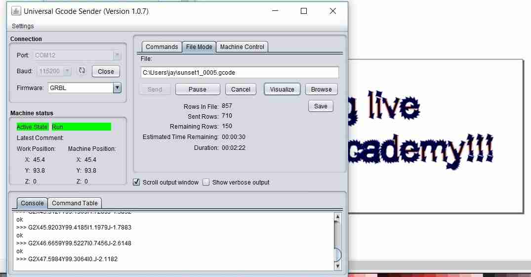
Please change the $100, $101, $130, $131 as per your document size and resolution. To change the $100 (x max travel, mm) value from 40 to 100, please enter in the command line $130=100 & hit enter. You can press $$ in the Commands tab to confirm. Now its time to stream g-code to the machine. Go to “FILE MODE” Tab. Browse to your g-code file and hit enter. The image shows the processing on the computer screen.
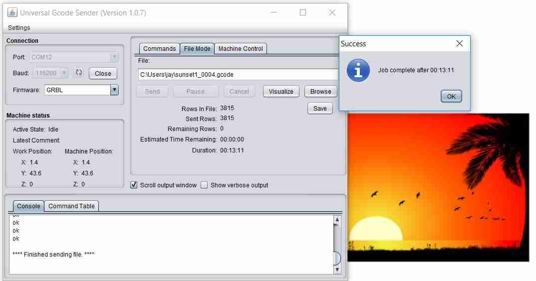
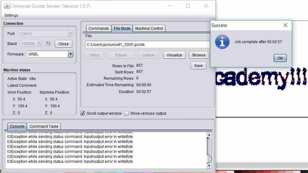
The image below shows the screen once the job has finished.
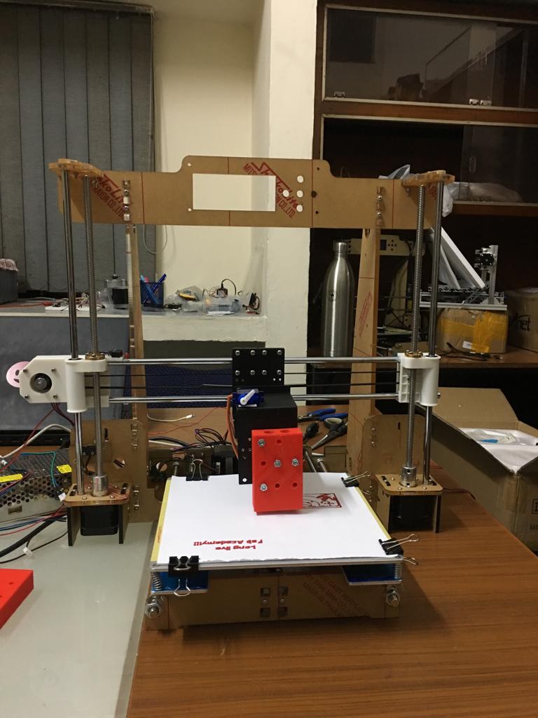
Working of the xy plotter
Sunset sketch
The below video is for the process explained above to create the g-code for the sunset sketch. The sunset sketch using the plotter:
The Pen lift mechanism in all its glory:
The view from the back side of the plotter:
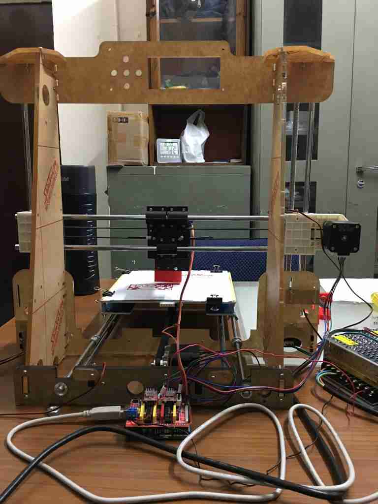
The view from the front side of the plotter:
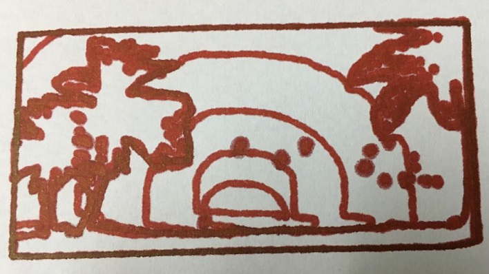
The final plot came out to be:
Text plotting
This video shows the other aspects of plotter’s mechanisms:
The images on the universal g-code sender.
The final text:)

Learnings
There were plenty of learnings along the way.
The Eureka moment!
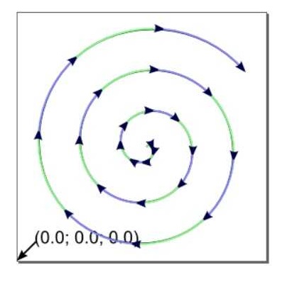
The following video shows the first runs of the plotter before the implementation of the pen lift mechanism. This was the Eureka moment as the machine showed the first signs of working. Please note that this was done on a spiral vector image from Inkscape.
Initial issues with pen lift
The below video shows some makeshift mechanism for pen lift to be ready for machine week video. As can be seen, shortcuts won’t cut it.
This lead to further perseverance in designing a proper pen lift slider shown in the documentation on this page before.
Way forward
This xy plotter just converts the vector image in Inkscape to a plot. But the homing hasn’t been applied. Secondly, to make this mechanism work the bed size got reduced. This could be improved. The resolution of the steppers could be refined using the jumpers on the GRBL shield.

Solar powered electric bike con kit by Jay Dhariwal is licensed under a Creative Commons Attribution 4.0 International License