15. Mechanical Design (May 8)
This week we were suggested:
For the Group assignment: 1. Design a machine (mechanism + actuation + automation) 2. Build the mechanical parts and operate it manually. 3. Document the group project
For the Individual assignment:
- Document your individual contribution.
Deciding the machine
We spent a lot of time brainstorming the machine to design and build. Some of the group members wanted to build a machine that could make another machine and others wanted to build an injection molding machine. I felt that this was too ambitious given that none of us in the group had built a machine before. I wanted the group to build something simpler to start with where we could get help from the instructors if we stumbled along the way, the parts for which were readily available so that we could finish within time and we had the necessary skills to finish the machine building in time. What we agreed on as a group was to build a modular machine which had a common motion control system for x, y and z directions. There should be scope to change the end-effector to achieve different functions such as adding an extruder system to make a 3d printer, adding a spindle for cnc engraver, a laser for laser cutting, a pen for a plotter, adding a microscope for a tele-medicine system, etc. All of us were excited to pursue this path. However, we couldn’t agree as a group for one specific machine. Part of the reason was also that the local fab lab is situated 2.5 hours one way for most of us and we have varying work schedules which made it difficult to work together. So we decided that few members of the group would work on building Hector, which is an open access medium sized CNC machine started by Jens as his fab academy project. Few others were intrigued by the idea of cardboard CNC and wanted pursue that. I felt that we should start off simple. I wanted to build a motion control system for x, y and z and make an xy plotter machine. This seemed achievable. If we are successful, others could learn from the mechanisms and electronics and they could also add further functionalities.
Mechanical Design
Mechanisms
The mechanisms used for x, y movement were timing belts. The timing belt is connected to pulleys on both sides. One of these pulleys is mounted on a stepper motor to give a step wise increment. The end effector bracket is mounted on the guide rods along the x axis with the help of linear bearings.
The pen lift mechanism was a sort of slider crank mechanism with the pen only having a single degree of freedom to move up and down in the z axis. The slider was actuated with the servo motor.
Actuation
The actuation was achieved with the help of nema 17 stepper motors. The stepper motors used A4988 motor drivers for getting the right current. The signal pins of motor drivers were connected to an Arduino Uno.
Automation
This machine was automated using CNC shield placed on an Arduino Uno. The stepper motors and the corresponding motor drivers, servo motor and power supply were connected to the CNC shield. GRBL 0.9 firmware was uploaded on Arduino Uno. Inkscape version 0.47 vector 2D software was used to create the sketch. An extension was used in Inkscape to convert the sketch to tool path in g code format. This g code was sent to the microcontroller using universal g code sender software for automation.
CAD model of the mechanical frame
We had purchased a DIY kit for making a 3d printer which inspired my mechanical design. I found the 3d assembly of the drawings of this DIY kit which I laser cut for creating my mechanical frame. I had intended to tweak the cad model in Solidworks to account for the kerf.
The image shows the assembly of the CAD model in Solidworks.
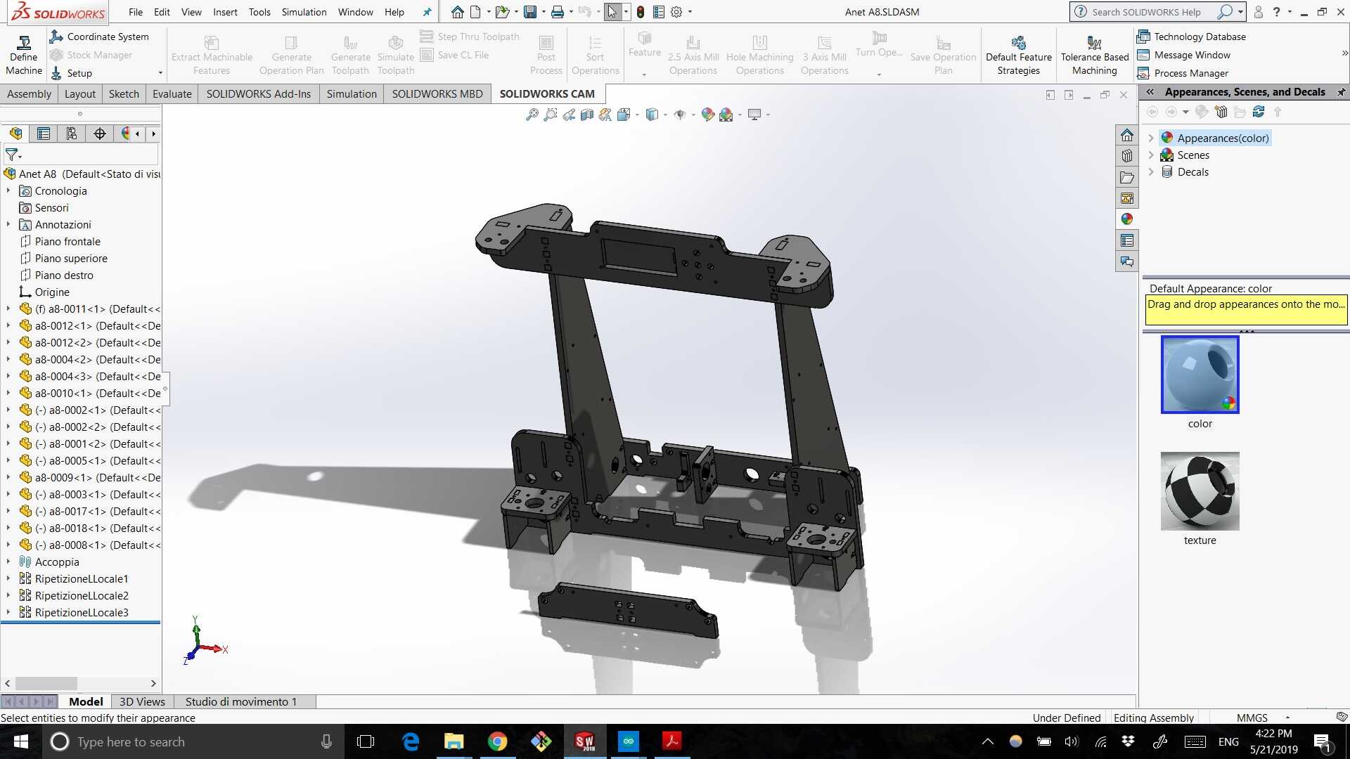
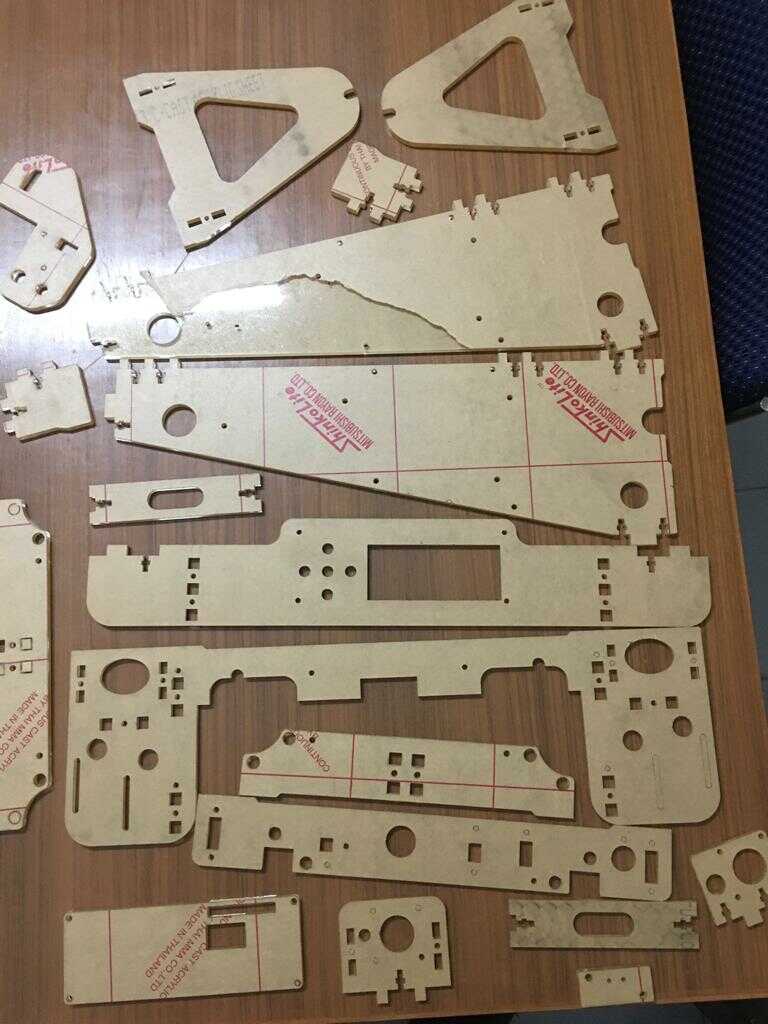
I created dxf files from Solidworks for laser cutting which can be downloaded from here. Using these designs, I laser cut all these parts from the acrylic that we had available in our local Fab Lab.
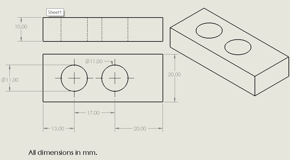
CAD model for the pen lift mechanism
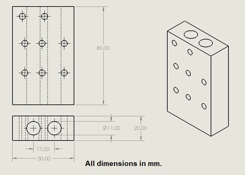
I added two brackets to mount the pen lift mechanism. The CAD for the components needed for the pen lift mechanism were designed by me.
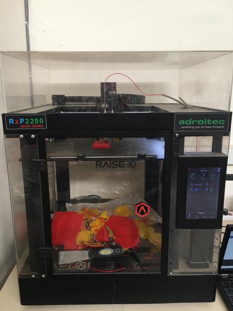
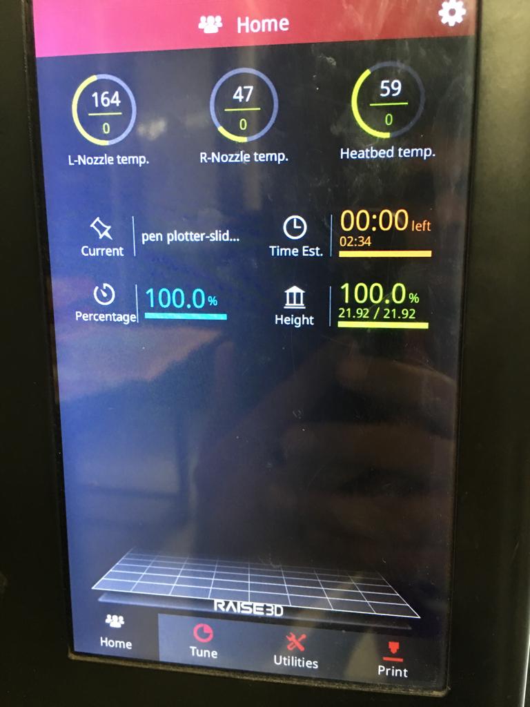
This CAD was converted into stl format. Then Ideamaker software was used to create the g-code.
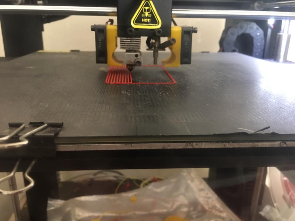
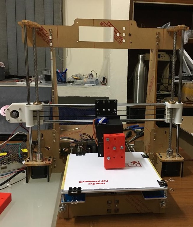
The 3d printer in my office was used to fabricate the slider support and the pen holder. This image shows the 3d printer.
This shows the raft getting created for the slider.
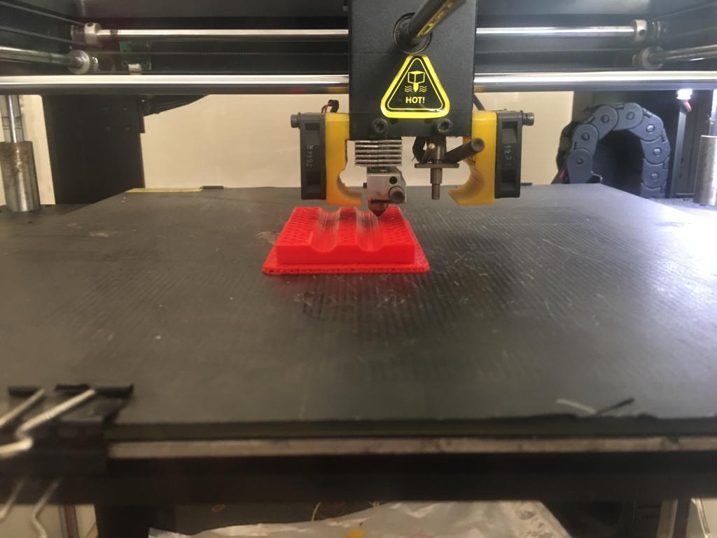
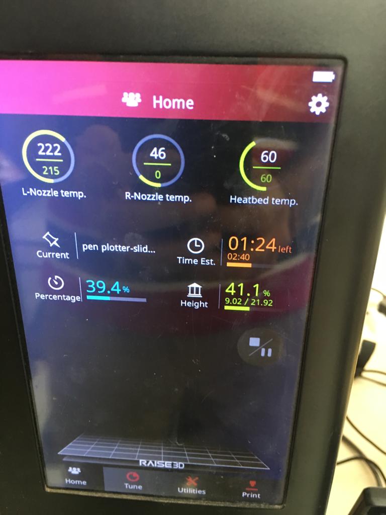
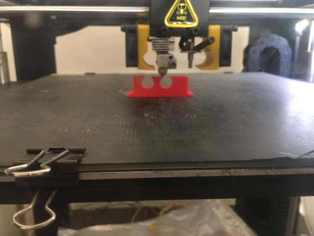
These images show the part in the process of getting 3d printed.
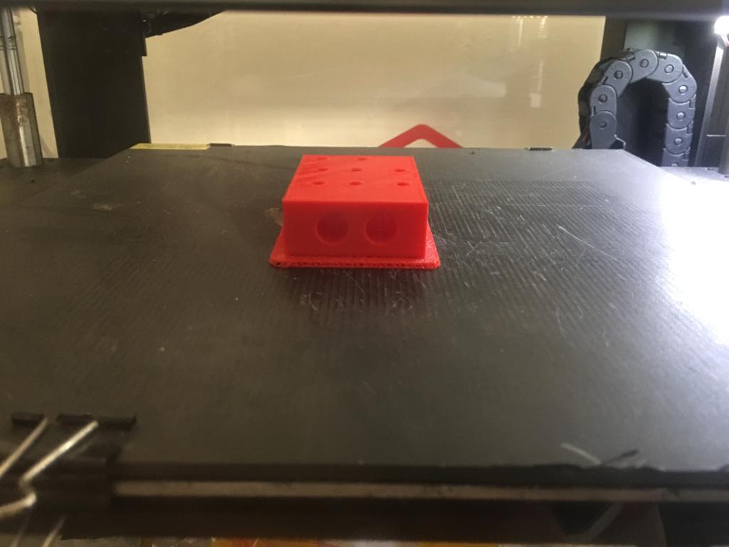
These images show the 3d printing process finished.
The below images are for the CAD and 3d printing of the pen holder.
Bill of materials (BOM)
Apart from the laser cut mechanical frame and parts for the pen lift mechanism, we needed:
- Nema 17 stepper motor with pulley for the x direction movement
- Nema 17 stepper motor with pulley for the y direction movement
- Two Nema 17 stepper motor with couplers for the z direction movement
- One micro switch 10t85 each for x, y and z direction homing
- Two M8 lead screw 345 mm in length, two M8 guide rods 380 mm in length for the z axis movement
- Two M8 guide rods 436 mm in length along the x axis
- Two M8 threaded rods 400 mm in length for y axis movement
- 7 Linear bearings for the bed of the machine and end effector connections
- Left and right z axis nut supports
- 12 V, 20 A power supply
- 220 mm X 220 mm Bed and bed aluminium plate
- Micro servo motor for pen lift
- End effector brackets
- Pen slider support
- Pen holder
- 1.6 m timing belt for x and y axis movement
- Arduino Uno
- CNC shield module for arduino Uno
- Four A4988 motor drivers for the stepper motors
Parts 1, 2, 3, 4, 10, 12 and 19 were available in the local market of the city. Part number 17 and 18 were ordered through amazon. Part number 14 and 15 were designed by myself and 3d printed. The other parts were not easily available so they were used from the diy 3d printer kit available in my work place.
Assembly of the mechanical frame
The components of the mechanical frame were assembled watching the following video.
The machine looked like this at this stage.
Demo of the manual operation
The xy plotter should move in the x and y direction and the pen lift mechanism should lift the pen in z axis.
The following video shows the manual operation in the x axis:
The following video shows the manual operation along the y axis.
This video shows the servo motor lift. The pen is placed in a slider support causing it to move only up and down along the z axis.
Learnings
All the group members also exchanged the learnings that they had in terms of the mechanisms explored and the electronics based automation that may be possible to assist each other. The group explored a variety of mechanisms such as rack and pinion mechanism, use of timing belts and lead screws for the linear motion.

Solar powered electric bike con kit by Jay Dhariwal is licensed under a Creative Commons Attribution 4.0 International License