16. Interface and Application Programming (May 15)
This week we were suggested for the Group assignment to write an application that interfaces a user with an input and/or output device that we made. For the individual assignment, we had to compare as many tool options as possible.
Thoughts
I wanted to relate this assignment to my project of making an e-bike conversion kit. I wanted to build a mobile App which could transmit the sensor values from my e-bike and the weather to my mobile App. To begin with, the sensors would include battery remaining, air temperature and relative humidity. I could add more parameters as my project advances.
MIT App Inventor
I thought of trying MIT App Inventor as it seems to be well suited for mobile app development the beginners. In the spirit of spiral development, I also thought of interfacing the temperature sensor with the mobile App using the Arduino. I would add my own pcb later along with more sensors.
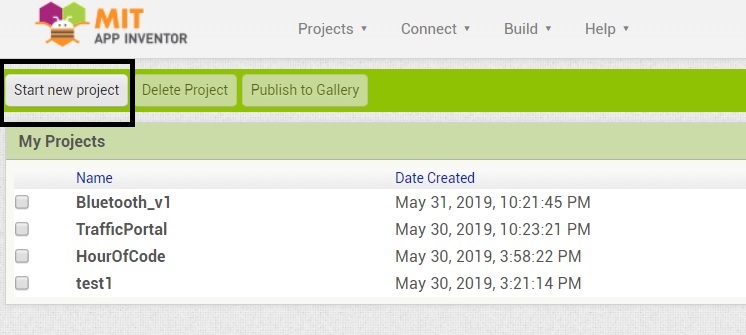
Firstly, we need to login to MIT App Inventor using our gmail account. Once we login to the cloud, we need to create a new project.
There are two editors in App Inventor. One is the Designer editor where the user interface is designed and the properties of the components are set. The other is the Block editor where the logic is programmed for the App to work. I followed this tutorial to create the user interface (UI) and program the logic.
Designer Editor
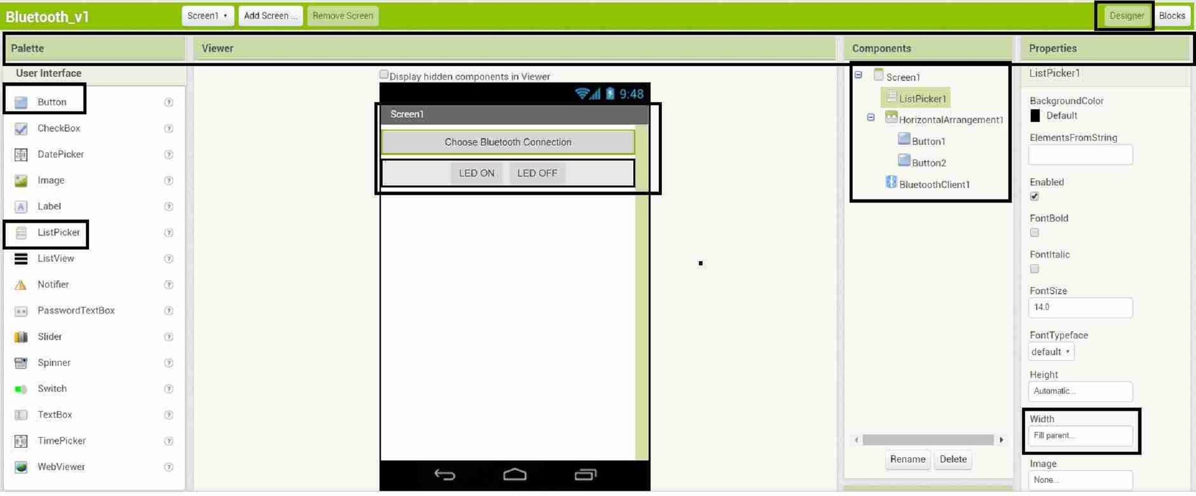
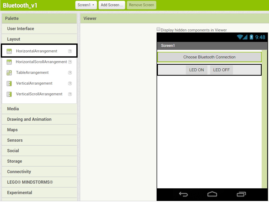
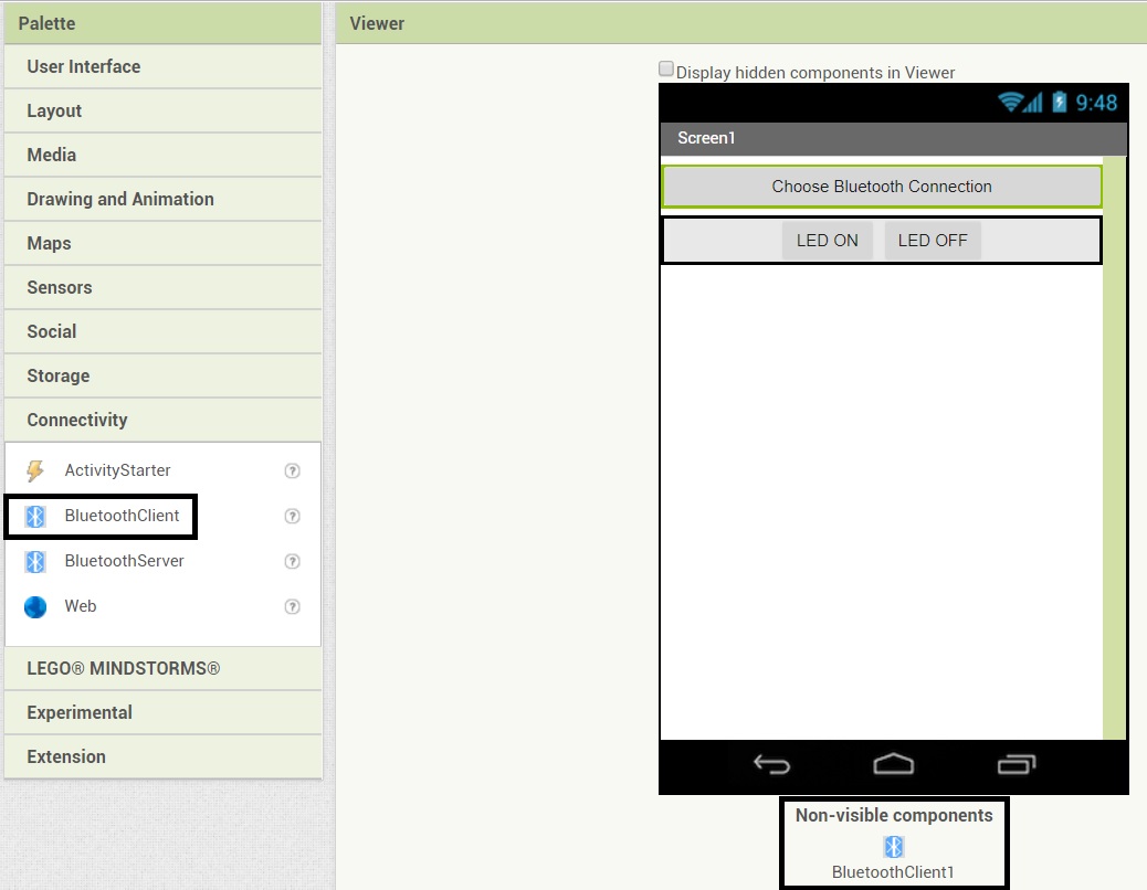
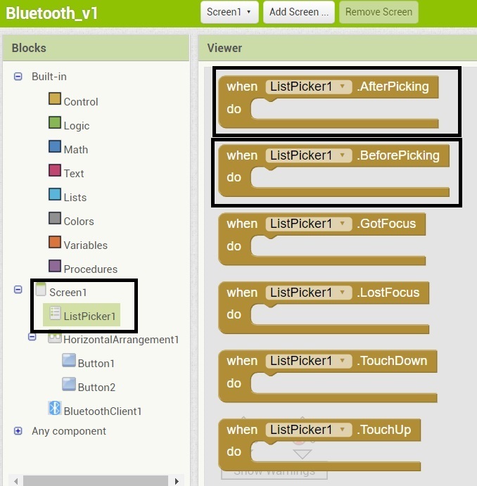
We start with the Designer editor. The below image gives an overview of designing the UI with the editor. The rectangular blocks have been drawn to show the highlights. There are four parts of the designer editor. The leftmost part is the palette where the components are placed. We use the Button and Listpicker components from the UserInterface of the Palette and place them in the Viewer. We use the Horizontal Arrangement component from the Layout of the Palette for layouting the Viewer. We also select the Bluetooth client component from the Connectivity section of the Palette and it appears as non-visible component in the Viewer. These components can be selected in the Components section to edit their properties in the Properties section. We change the Listpicker Width property to Fill the parent. Likewise, we change the text for the Listpicker, Horizontal Arrangement and the Buttons.
Blocks Editor
The next step is to program the logic for these components in the Blocks Editor. We select the Listpicker from the Blocks section to find out what functions are possible with this component. We pick the ListPicker1.BeforePicking and ListPicker1.AfterPicking.
Likewise, we can pick code blocks for the Buttons and the Bluetooth Client.
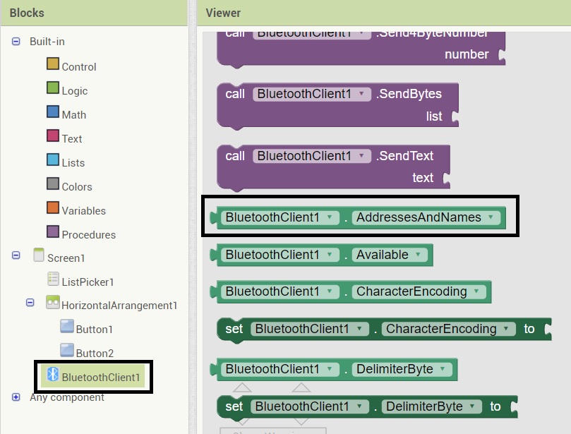
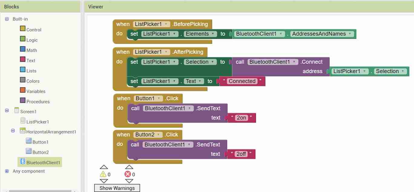
This image shows the complete code for the Blocks editor. The Listpicker1.BeforePicking function provides the list of the Bluetooth Addresses with Names to choose from. The ListPicker1.AfterPicking function gets activated after a Bluetooth address is picked from the list and it changes the text to Connected once it establishes the connection. Button1 is for sending the text “2on” serially to arduino and Button2 is for sending the text “2off” serially to arduino.
Connect to Android Phone
After we have set up our App, we need to connect our App to the android phone to see how it works on the phone. We need to download and install MIT App Inventor from the google play store on our phone.
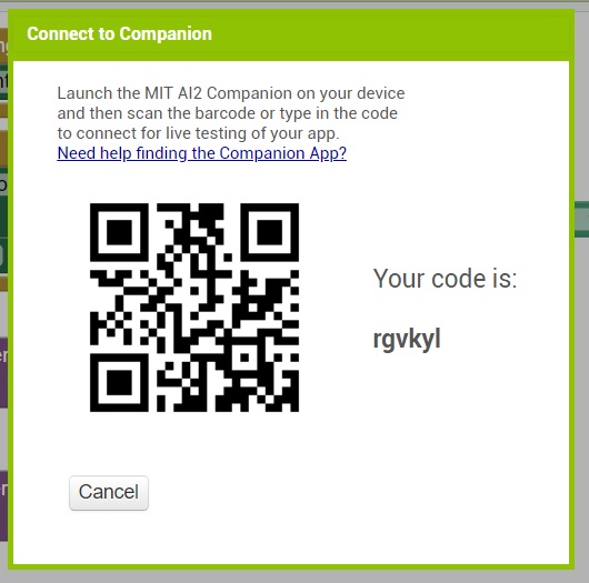
Next we need to open the App Inventor on the phone and then Connect to AI Companion.
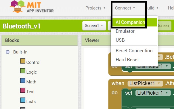
We need to enter this code in the App in the phone.
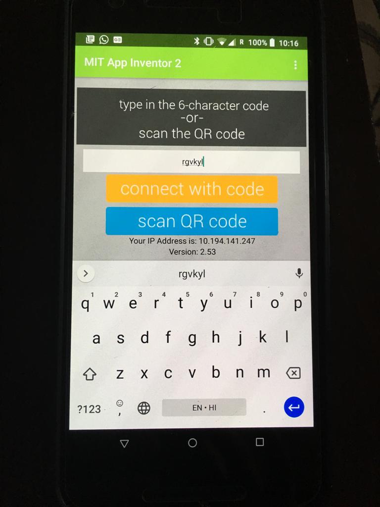
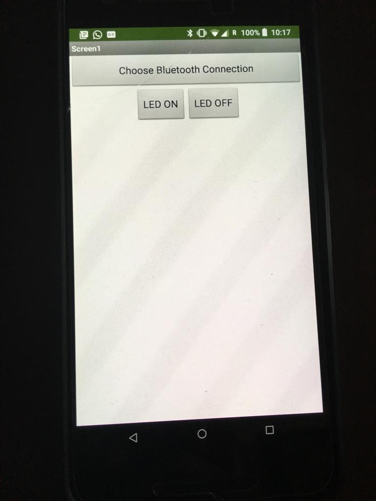
Once we connect with the code, our created app appears on the phone.
Arduino code and connections
The guidance has been taken for the Arduino code and connections corresponding to the mobile App and have been modified.
The code can be downloaded. While uploading this code, please remember to remove the Bluetooth Tx and Rx pins otherwise the code won’t serially get communicated to the microcontroller.
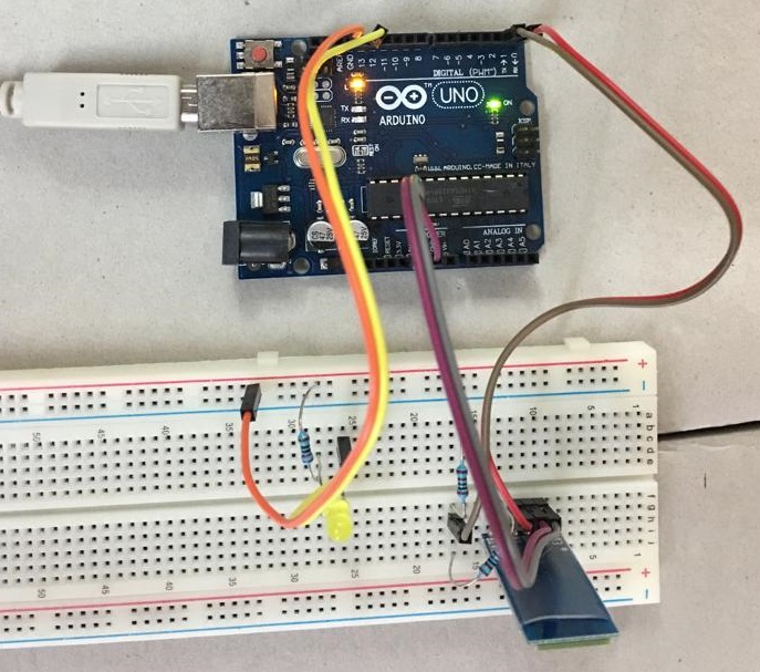
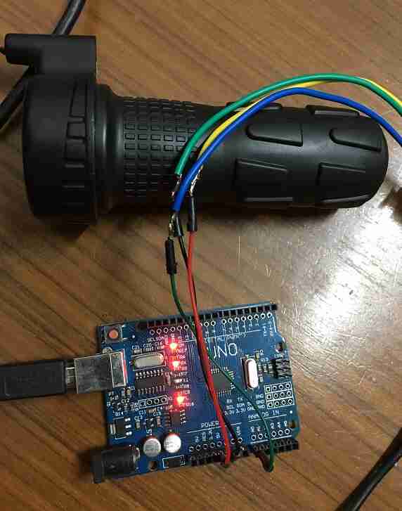
The connections are pretty basic as per the image below. The only thing to remember is that the Rx pin in bluetooth can only take 3.3 V so we need to create a voltage divider circuit with resistors to convert 5 V to 3.3 V. If 5 V is directly connected to Rx pin of Bluetooth then it would fry the module.
Demo
The demo of the mobile App and the LED setup working together can be seen at:
In the video above, firstly, the bluetooth address is selected. Once it is connected, the LED can be turned on and off using the buttons.
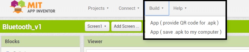
App in Play Store
If one wants to launch the app in google play store with App Inventor, then one needs to first save the .apk file of the App as per the image below. Other options to share and package are also there.
To launch apps, one also needs to pay USD 25 one time fee to get access to the google play console. Once you have access, please search for instructions of how to publish the app in google play store. I plan to publish my project’s app in google play store.
Processing
I also wanted to try out Processing since this can be used to integrate sensors and actuators on the laptop easily. Processing is very graphics based language. Arduino programming environment is also heavily based off of it.
Firstly, I downloaded Processing and started with beginner tutorial. The guidance for code in arduino and processing was taken.
Another tutorial for serial communication was also useful to get started.
Bike throttle screen color changing
I wanted to change the color of my form in Processing based on the reading from the bike throttle of my project. The bike throttle is essentially a potentiometer whose value changes as the throttle moves back and forth. I have talked about it on my project page.
The connections to the Arduino are pretty basic. One wire to 5V, ground and A0 each. The Arduino code is:
//throttle check with multimeter and 5V dc supply
//https://www.youtube.com/watch?v=GDnI4HA_QyY

void setup() {
  Serial.begin(9600);
}

void loop() {
  // read the throttle input on analog pin 0:
  int sensorValue = analogRead(A0);
  // print out the value you read:
  Serial.println(sensorValue);
  delay(2);        // delay in between reads for stability
}
The corresponding code in Processing is:
// Youtube tutorial at https://www.youtube.com/watch?v=g0pSfyXOXj8
//Code modified from https://www.jeremyblum.com/2011/02/07/arduino-tutorial-6-serial-communication-and-processing/
//Program by Jeremy Blum
//www.jeremyblum.com
//Uses pot data from arduino to draw stuff

import processing.serial.*;
Serial port;
float brightness = 0;

void setup()
{
  size(500,500);
  port = new Serial(this, "COM30", 9600);
  port.bufferUntil('\n');
}

void draw()
{
  background(0,0,brightness);
}

void serialEvent (Serial port)
{
  brightness = float(port.readStringUntil('\n'));
}
This connects to Arduino over serial at port COM30. It draws a square of size 500 by 500 pixels. It changes the brightness of this square based on the throttle value. The below video shows this effect.
Summary
I compared two options for this week. One was Mobile App development using MIT App Inventor and lighting up an LED with Bluetooth. The other was to control a GUI in Processing with a throttle of my bike project.

Solar powered electric bike con kit by Jay Dhariwal is licensed under a Creative Commons Attribution 4.0 International License