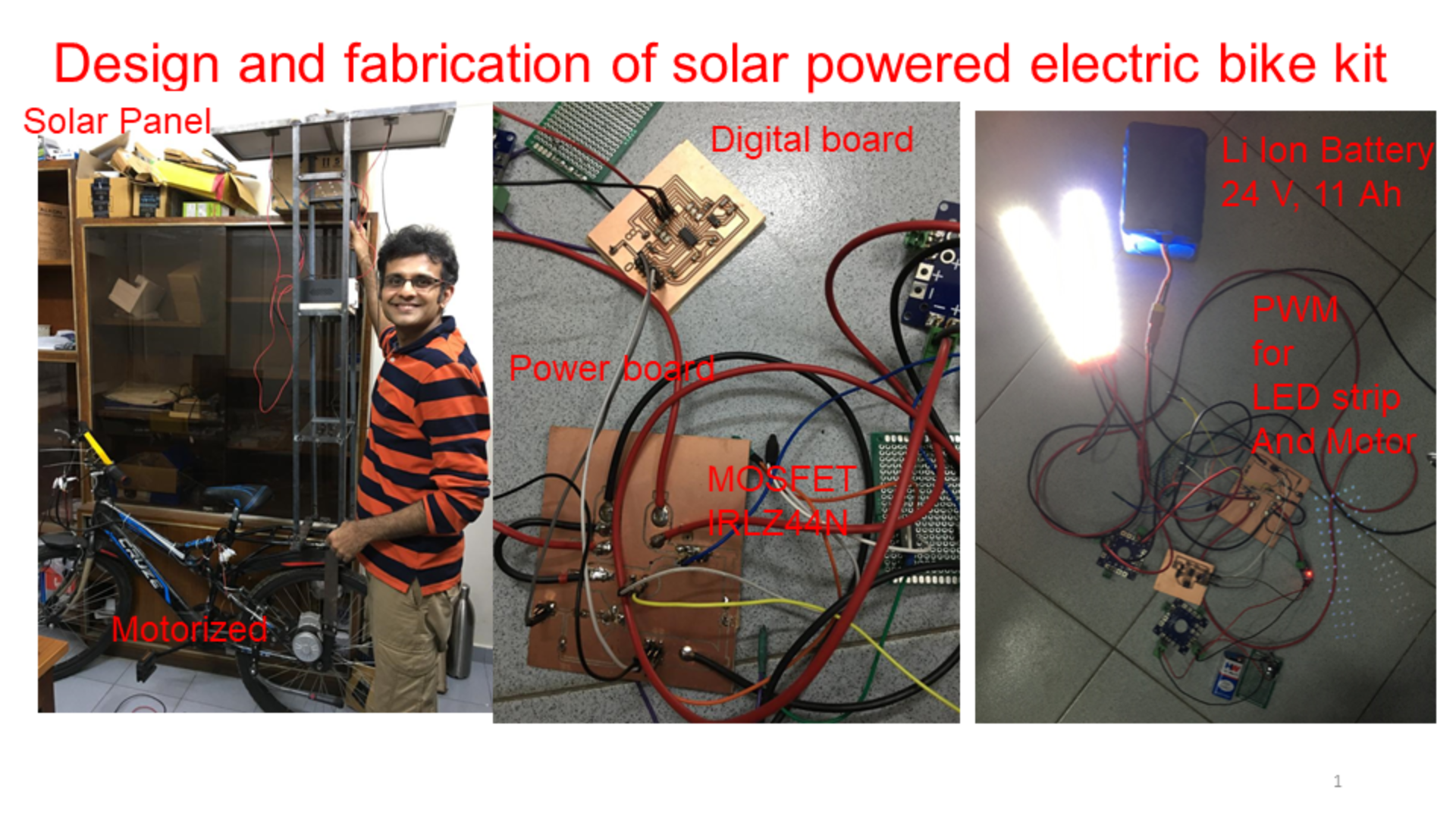
Final project
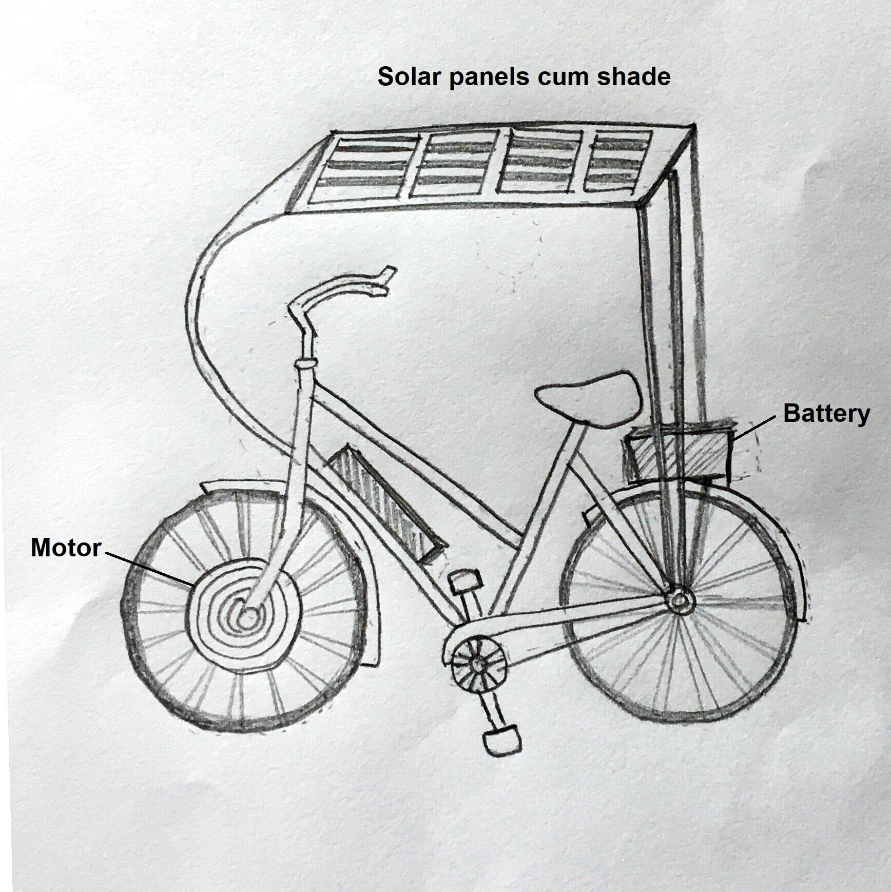
As outlined in my project proposal, I am working on developing a solar powered, electric bike conversion kit for a bicyle. The solar panels double up as a source for battery power and a sun-shade.
An initial sketch of my final project.
Sizing of Solar powered electric bike
This section gives a sense of the rough cut sizing calculations for my bike’s components.
Assuming that I would use the electric bike features for 40 minutes/day, I wanted to keep the speed slow to be around 15 km/hour to begin with to be safe. This gives me my range of 10 km for the battery.
I am getting a cheap e-bike kit with the DC motor rated at 250 W, 24V which suggests that the maximum current that the bike would get would be as per:
P = VI or I = 250/24 ~ 10 A.
The size of the Lithium Ion battery needed while accounting for losses would be 10 A for 40 minutes/day = 6/0.7 ~ 10 Ah or more.
For Solar PV Panels, I thought of starting off with smaller size solar panels which would not take much space and could charge the Lithium ion battery in one day.
Energy needed = 10 Ah X 24 V = 240 Wh.
Two 20 Watt-peak Solar Panels of size 24 cm by 32 cm with a solar insolation of 1 kW/m2 for 8 hours in summer accounting for losses reducing the energy by 20% would give us 20 X 2 X 8 X 0.8 = 256 Wh of energy, which is above the required energy.
E-bike kit
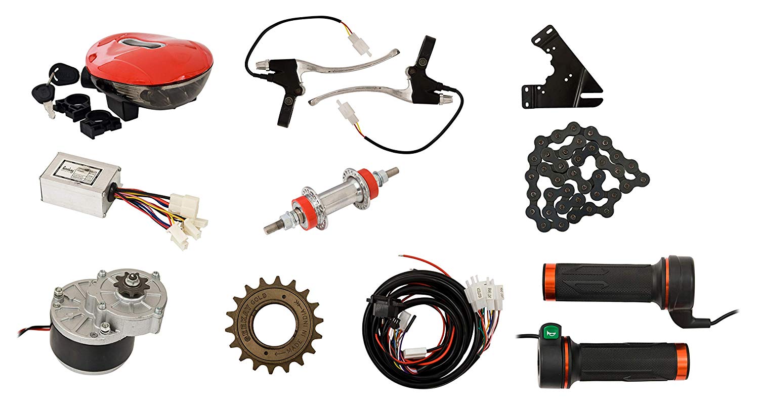
I am following the process of spiral development. My initial aim is have a working e-bike by Feb 2019 end. I have ordered a cheap e-bike kit locally available in India.
After I assemble the e-bike kit, I would like to size the solar panel and order it. I would then use a structure to add the solar panel to act as a sun-shade to my e-bike. After this step, I would like to refine my design with my Fab Academy 2019 skills.
BOM
- Bicycle
- e-bike kit with 250 W, 24 V DC motor, Throttle with wiring, brakes with wiring.
- Lithium Ion battery 24 V, 11 Ah
- 2 Solar PV Panels of 20 Wp each with a size of 24 cm by 32 cm, PWM solar charge controller were procured locally.
- Two 12 V LED strips procured locally
- To make a composite sun shade, I needed wood to make the mold which was there in the lab. I ordered resin. Jute was freely available with the vegetable vendor.
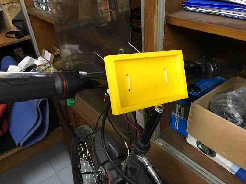
- Smart phone bike mount was 3d printed.
- PCB boards were milled.
- Components such as MOSFETs, ATtiny44 and other components were either there in the Fab Lab or were ordered through element14.
Further details on the BOM can be seen in week 13.
Skills to be used in the project
I have incorporated 2D and 3D design, additive and subtractive fabrication processes, electronics design and production, microcontroller interfacing and programming. I am working on the system integration and packaging. I have attempted to make whatever was feasible. I have made the following parts:
- PCB for ATtiny44 digital board
- PCB for the power board for motor controller and the LED strip
- PCB for battery monitor
- Smart phone bike mount
- Composite sun shade
I am working on making a weather proof casing for packaging the PCBs.
The first spiral - assembled bike kit and bike
I have completed the first spiral for my project. I have assembled the bike kit.
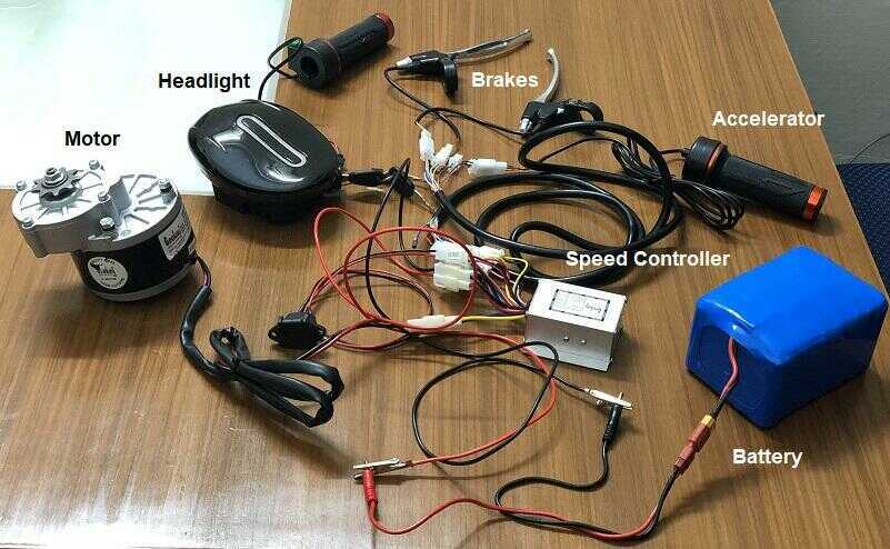
This video shows the various functions of the bike kit. The bikelight has a battery indicator and a headlight. The accelerator controls the speed of the geared motor. If the brake is pressed then the motor stops even if the accelerator is being pressed. The left handle has a horn as well.
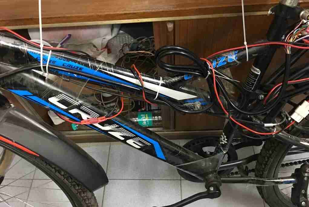
After testing the bike kit, I went to a bike mechanic to put the bike kit on the bike. I was initially planning to do it myself but since the hub of the bike had to be replaced and spokes had to removed from the older hub and put into the new hub, I took help. I also asked them to change the brakes due to safety reasons. I will learn to work with the brakes myself later. I will add more pictures about this process later. The assembled bike pictures have been shared below.
I bought a cheap bike to keep the cost of the project low.
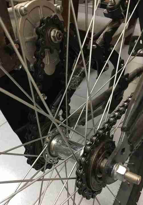
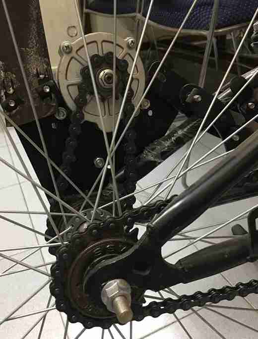
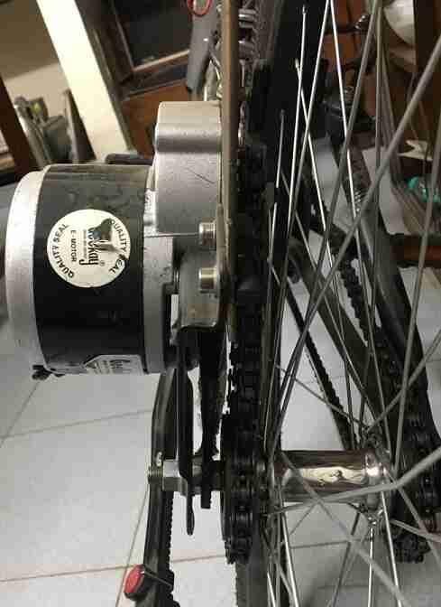
The next few images show different views of how the motor was mounted on the bike and the bike sprocket was connected to the hub of the bike.
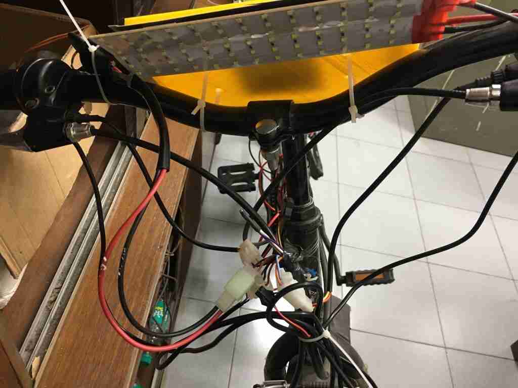
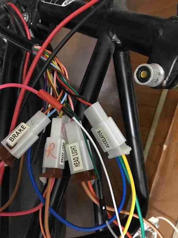
This image shows the connectors for the brakes, ignition switch, throttle and LED strip in the front of the bike.
This image shows the connectors for the brakes, ignition switch, throttle, LED strip and motor at the back of the bike.
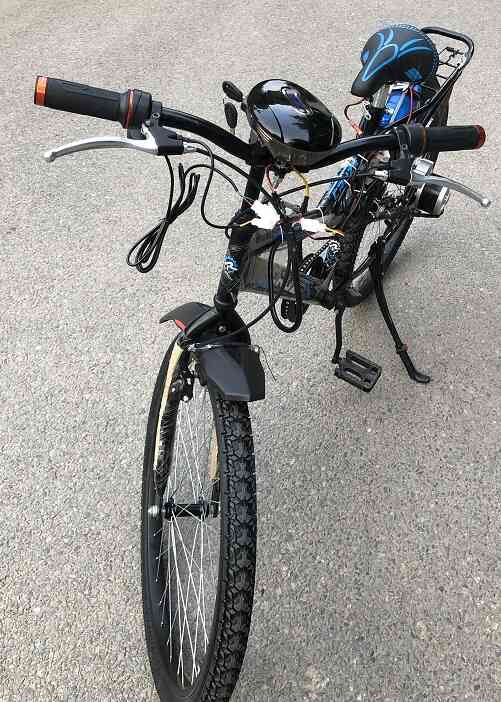
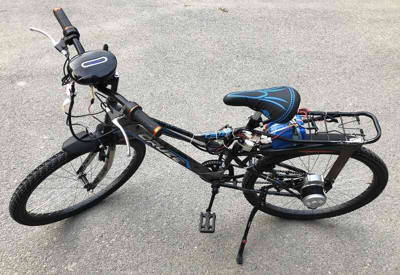
These images show the bike fully assembled with the e-bike kit.
This video shows me riding the e-bike in IIT Delhi campus. I actually rode it for 3 km in heavy traffic for the torture test of the bike :) and it didn’t let me down.
Next possible spirals
I would like to make the speed controller myself and improve it by integrating it with a smart phone app via bluetooth. I would like to estimate the distance that the bike would run for on the remaining battery.
I would also like to add an air quality sensor which should prompt the user to wear a mask if the air quality is poor.
If time permits, I would like to add a sun shade with a solar panel which would extend the range of the battery.
Another project could be to charge the battery when the person is pedaling.
This Lithium Ion battery system could also be built in different shapes for the aesthetics of the bike.
The second spiral
My next objective is to understand, design and build the pcb of the existing speed controller to extend its functionality and I am really excited.
I am planning to make a speed controller for my e-bike pmdc motor for my project. I want to add more functionality to my speed controller but after I solve this spiral.
I am planning to make one component work at a time and then integrate them together.
Understanding the working of components
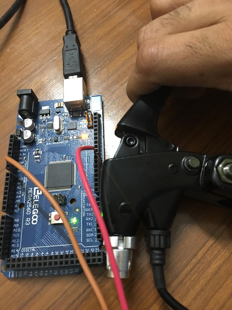
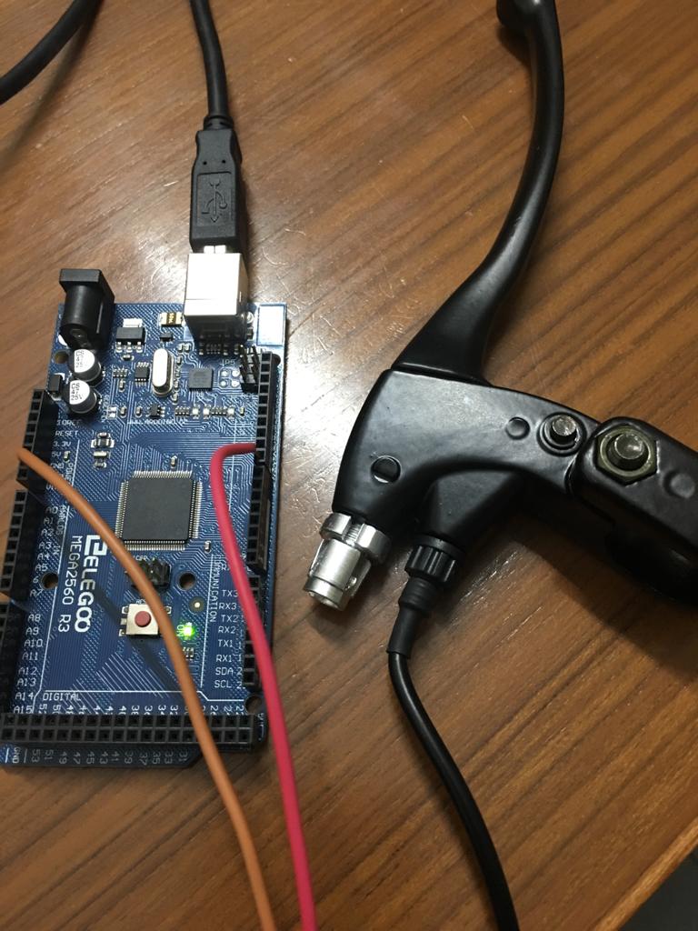
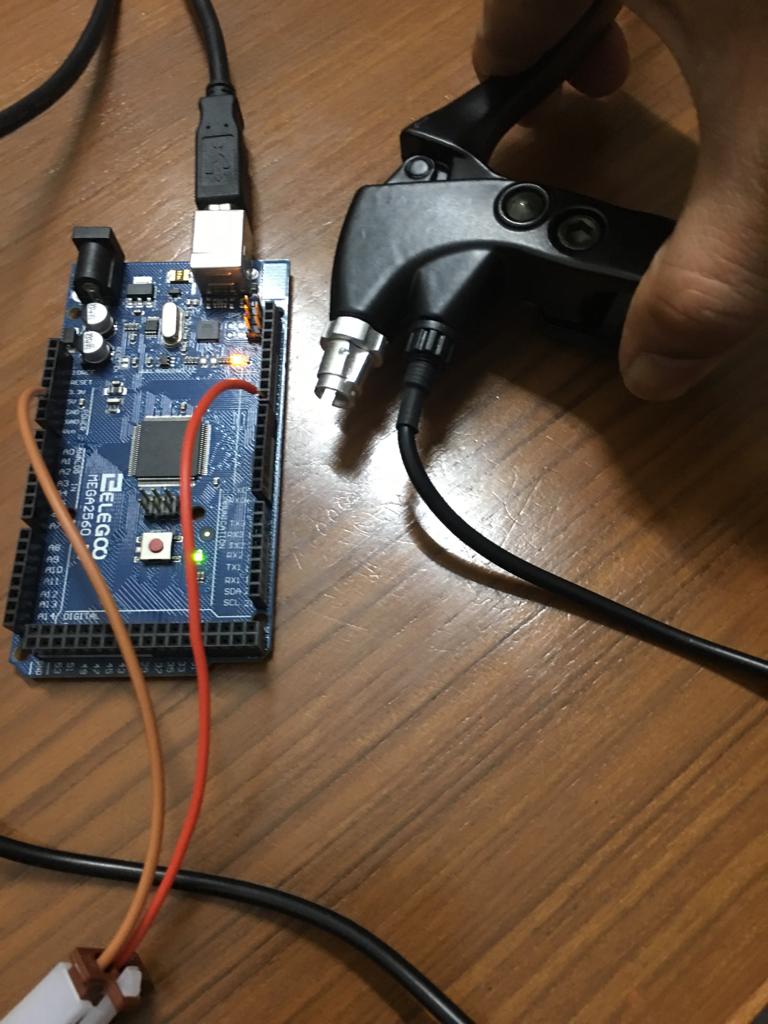
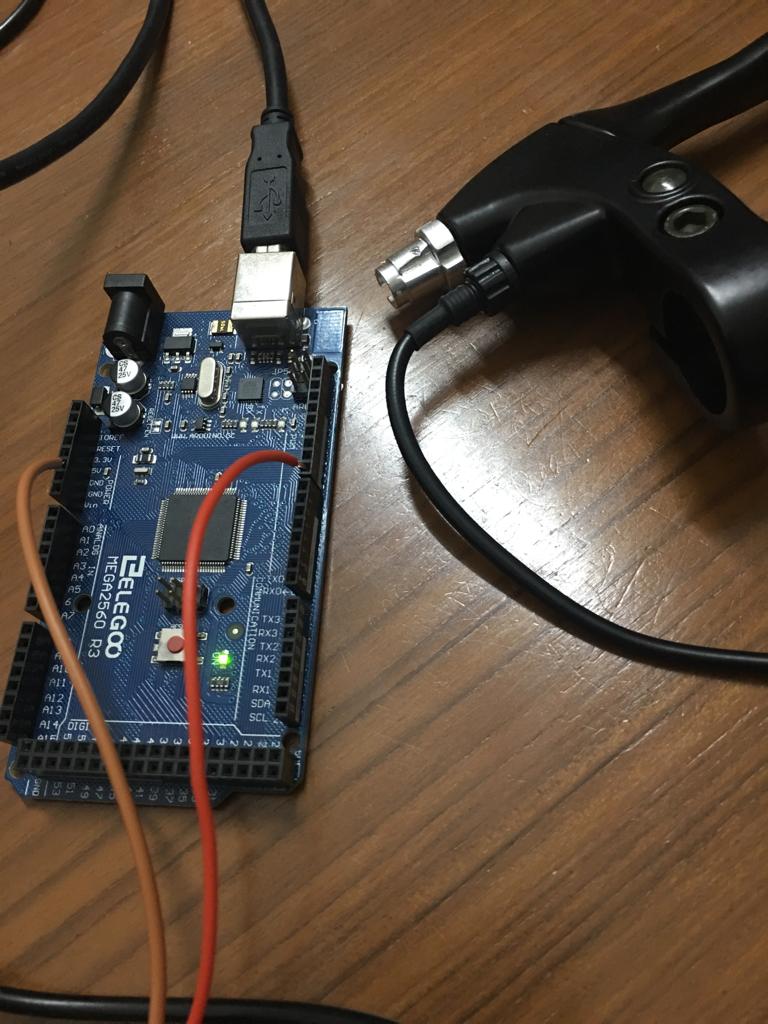
Throttle
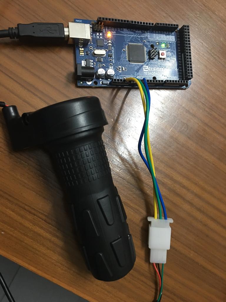
I connected the throttle wires to arduino. The wires went to 5V, ground and analog read pins.
This was the code used:
//throttle check with multimeter and 5V dc supply
//https://www.youtube.com/watch?v=GDnI4HA_QyY

void setup() {
  Serial.begin(9600);
}

void loop() {
  // read the throttle input on analog pin 0:
  int sensorValue = analogRead(A0);
  // print out the value you read:
  Serial.println(sensorValue);
  delay(1000);        // delay in between reads for stability
}
The serial monitor values changed from low to high and back to low as I turned the throttle from low to high and then back to low.
171
170
170
189
293
377
483
539
583
664
708
759
872
879
880
880
880
874
716
624
464
191
174
171
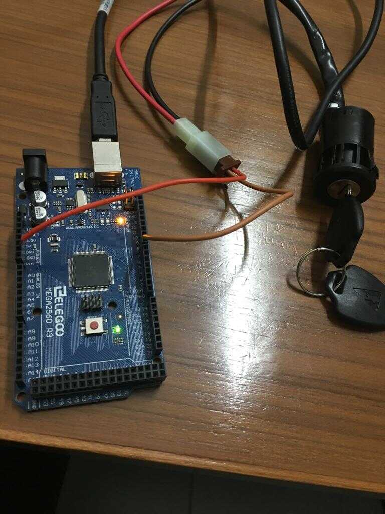
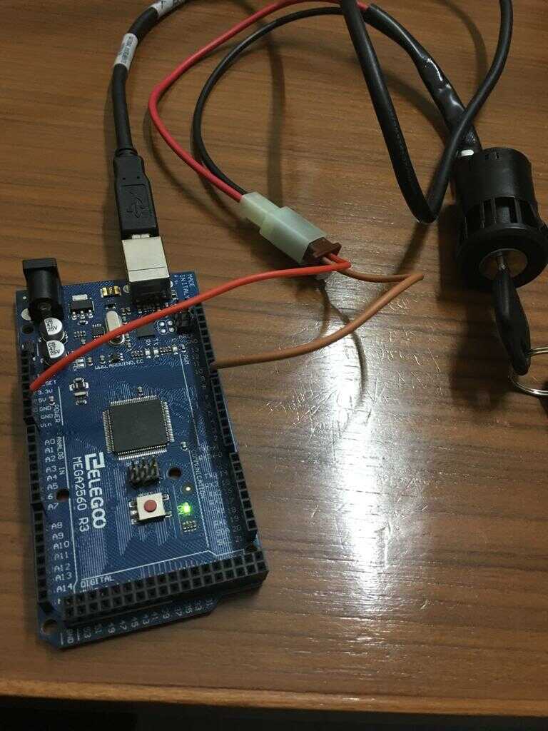
Ignition key equivalent
The ignition key equivalent is a switch. I tested it with mutlimeter and then the arduino using the input pullup resistor.
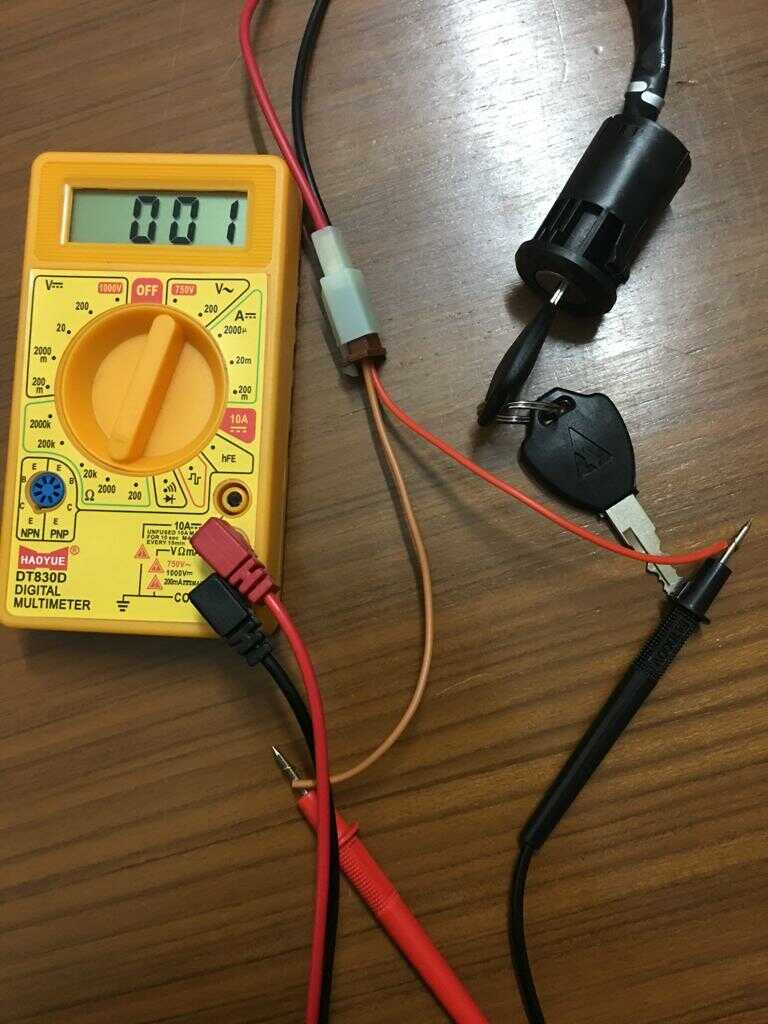
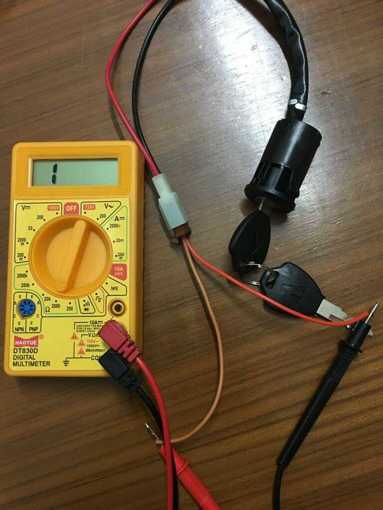
When the ignition key is turned on, the inbuilt LED lights up and vice versa.
int ledPin = 13;
int buttonApin = 8;

void setup()
{
  pinMode(ledPin, OUTPUT);
  pinMode(buttonApin, INPUT_PULLUP);
}

void loop()
{
  if (digitalRead(buttonApin) == LOW)
  {
    digitalWrite(ledPin, HIGH);
  }

  if (digitalRead(buttonApin) == HIGH)
  {
    digitalWrite(ledPin, LOW);
  }
Brakes
The same code as for the ignition worked for brakes as well since brakes are also switches. I tested it on both the brakes.
PWM motor control with N channel Mosfet
The PMDC motor can be controlled using the PWM signal from the uC. The PWM channel can be amplified using an N channel Mosfet.
I got the schematic of this circuit from google images and then modified it for my needs.
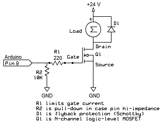
The MOSFET used was IRLZ44N
The Schottky diode used was IN5819.
The circuit was implemented on the breadboard using an Arduino Mega 2560.
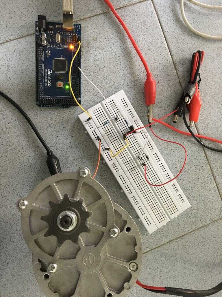
The fade LED code was used to increase and decrease the speed of the motor with PWM signals.
/*
  Fade

  This example shows how to fade an LED on pin 9 using the analogWrite()
  function.

  The analogWrite() function uses PWM, so if you want to change the pin you're
  using, be sure to use another PWM capable pin. On most Arduino, the PWM pins
  are identified with a "~" sign, like ~3, ~5, ~6, ~9, ~10 and ~11.

  This example code is in the public domain.

  http://www.arduino.cc/en/Tutorial/Fade
*/

int led = 3;           // the PWM pin the LED is attached to
int brightness = 0;    // how bright the LED is
int fadeAmount = 5;    // how many points to fade the LED by

// the setup routine runs once when you press reset:
void setup() {
  // declare pin 3 to be an output:
  pinMode(led, OUTPUT);
}

// the loop routine runs over and over again forever:
void loop() {
  // set the brightness of pin 3:
  analogWrite(led, brightness);

  // change the brightness for next time through the loop:
  brightness = brightness + fadeAmount;

  // reverse the direction of the fading at the ends of the fade:
  if (brightness <= 0 || brightness >= 255) {
    fadeAmount = -fadeAmount;
  }
  // wait for 30 milliseconds to see the dimming effect
  delay(30);
}
This circuit can also be connected to a battery in place of a dc power supply. This circuit can be extended to integrate with the throttle.
Headlight
I made the headlight out of a strip of 42 LEDs which I bought for less than a US dollar. This had 14 parallel lines with 3 LEDs in series with the resistor each and so was powered with a 12 V connection.
The led strip when switched on, had a very bright light.
Implementing LED strip with PWM in Arduino
The fade LED code was used to increase and decrease the fading of LED with PWM signals in the same way as done for the DC motor.
/*
  Fade

  This example shows how to fade an LED on pin 9 using the analogWrite()
  function.

  The analogWrite() function uses PWM, so if you want to change the pin you're
  using, be sure to use another PWM capable pin. On most Arduino, the PWM pins
  are identified with a "~" sign, like ~3, ~5, ~6, ~9, ~10 and ~11.

  This example code is in the public domain.

  http://www.arduino.cc/en/Tutorial/Fade
*/

int led = 3;           // the PWM pin the LED is attached to
int brightness = 0;    // how bright the LED is
int fadeAmount = 5;    // how many points to fade the LED by

// the setup routine runs once when you press reset:
void setup() {
  // declare pin 3 to be an output:
  pinMode(led, OUTPUT);
}

// the loop routine runs over and over again forever:
void loop() {
  // set the brightness of pin 3:
  analogWrite(led, brightness);

  // change the brightness for next time through the loop:
  brightness = brightness + fadeAmount;

  // reverse the direction of the fading at the ends of the fade:
  if (brightness <= 0 || brightness >= 255) {
    fadeAmount = -fadeAmount;
  }
  // wait for 30 milliseconds to see the dimming effect
  delay(30);
}
This is the schematic for the electronic connections.

The video gives the demo for the PWM control of LED strip.
DPDT switch
I added a DPDT switch from these articles, link1 and link2.
Solar panel
I wanted to add solar panels to the electric bike as they would act as a shade from the sun as well as charge the battery while on the road thereby increasing the range of my electric bike. India gets a lot of sun so Solar PV would be relevant. Although I do understand that with the increase in temperatures the efficiency of solar panels does come down so we could optimize the solar panels in the long run.
The sizing of the Solar Panels has been given in the section above on sizing.
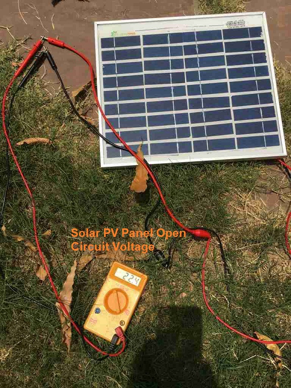
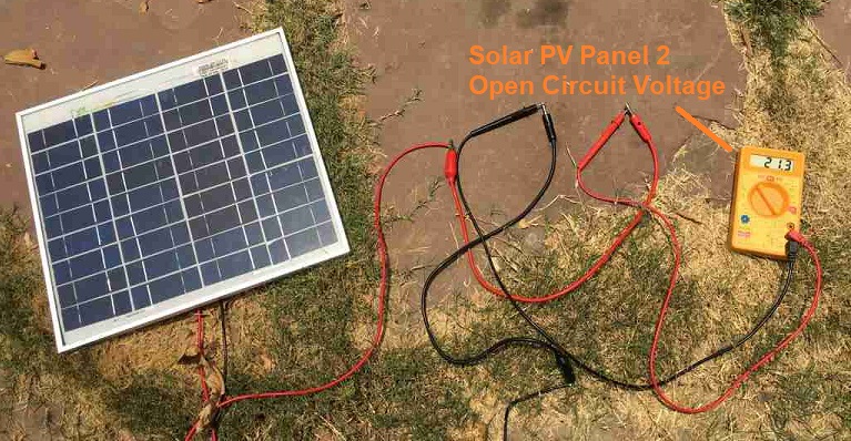
Solar PV testing
The first parameter to test for Solar panels is the open circuit voltage (OCV). The image below shows that OCV is well beyond 12 V for both the panels.
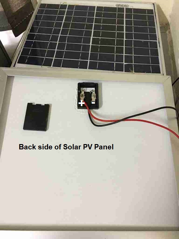
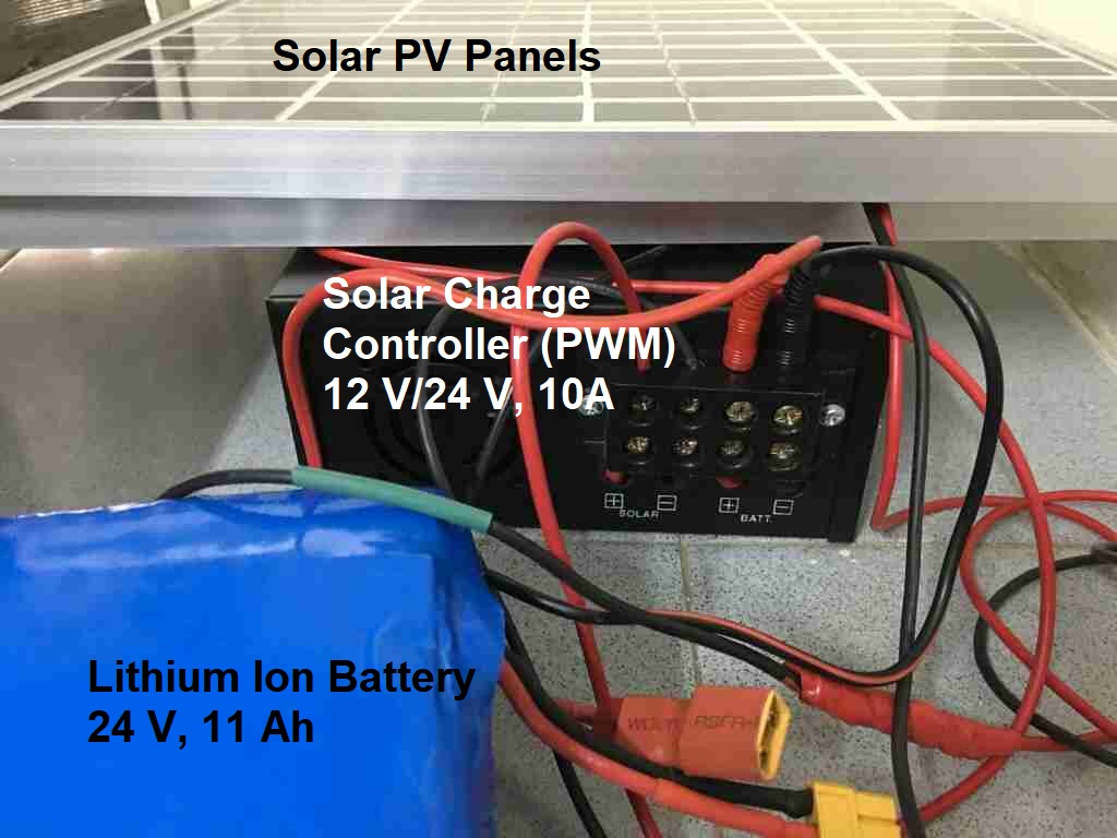
This image shows the connections on the back side of the Solar Panel.
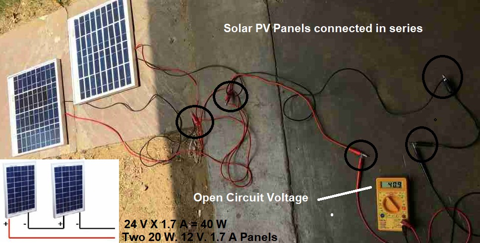
We connect the solar PV panels in series to get a voltage above 24 V. We are getting an OCV well beyond 24 V.
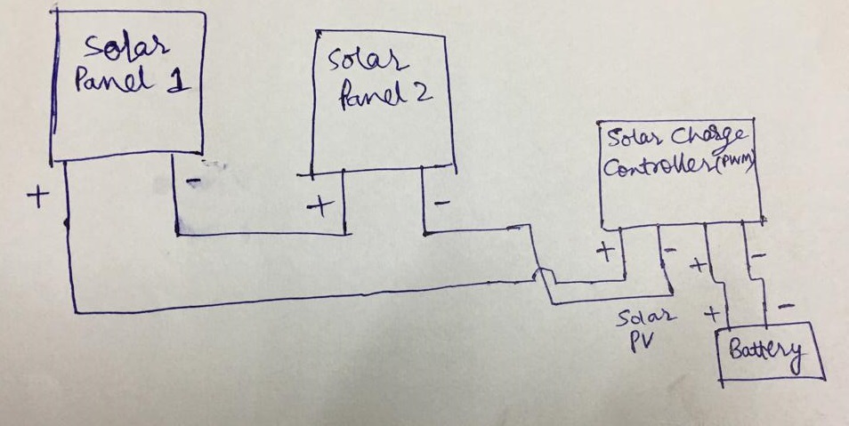
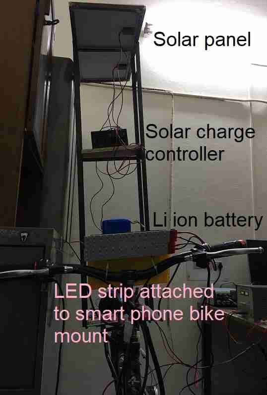
We use a solar charge controller which converts the voltage from the Solar PV panel to the rating of the battery so that the battery doesn’t get damaged. Our PWM based solar charge controller converts the 40 V or so from the solar panel to 24 V for the battery. The below image shows the schematic of the connections to be made. This is assuming that the battery is getting charged from the Solar Panels and then the battery would be used with the bike later.
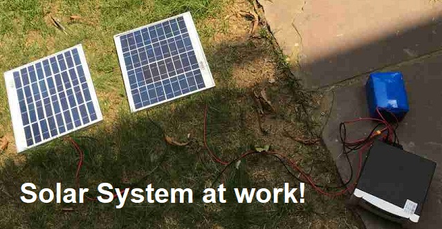
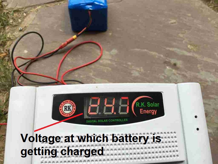
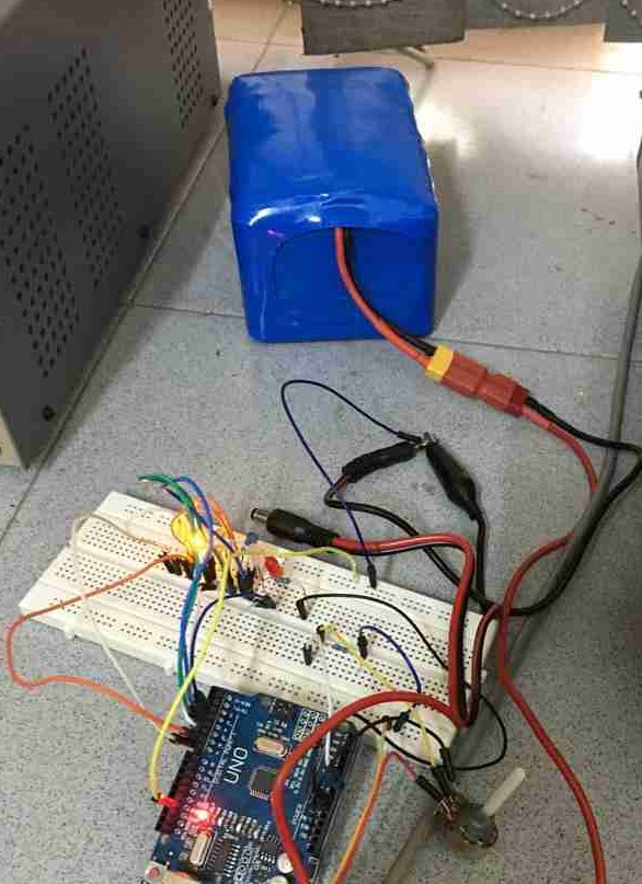
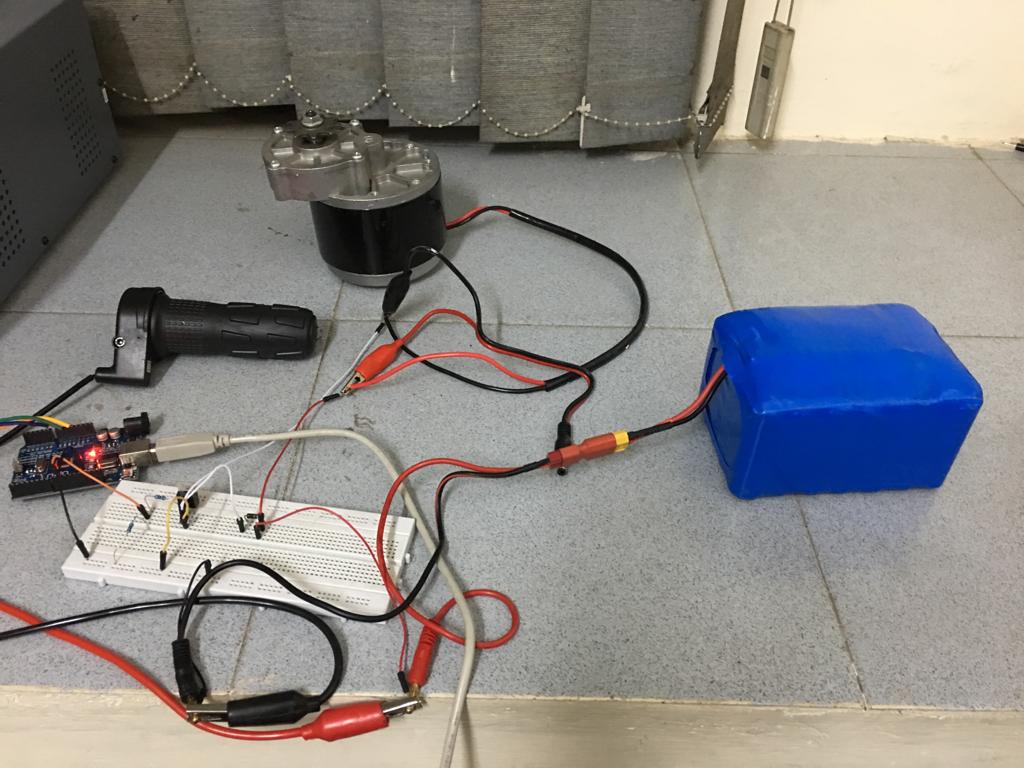
This shows the testing of the solar system at work charging the battery.
The controller has converted the voltage to 24 V for the battery.
Battery monitor
I would like to have a sensor which can let me know the battery remaining. It is crucial to not let the battery over discharge as it may get damaged. The Lithium Ion battery specs are 6S5P configuration with 3.7 V, 2.2 Ah per cell giving a voltage range of 20 V to 25.2 V and the current capacity of 11 Ah. It comes with a BMS to prevent over-discharging.
If we look at a typical discharge characteristics of a Lithium Ion Battery for 10 A, which is our case then we find that the curve is very linear in most of the range with the voltage decreasing linearly. 1C means a battery can give 1 A for an hour.
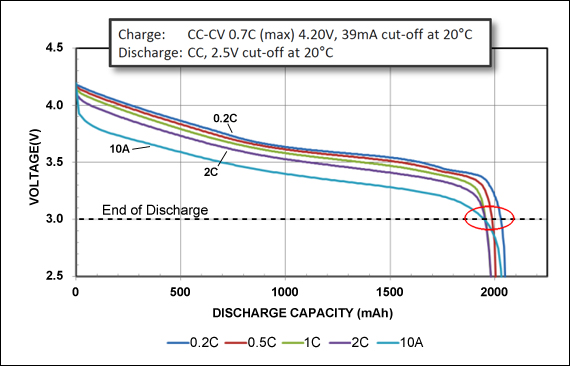
So, we can use the battery voltage as a proxy to find the % charge remaining in a battery.
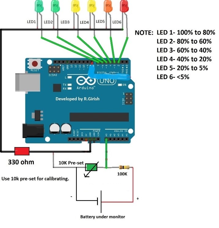
I used this article for guidance on making my own battery level indicator.
The circuit was intially made on Arduino.
This is the corresponding code in Arduino IDE:
//https://www.homemade-circuits.com/battery-level-indicator-circuit-using/
//--------Program developed by R.Girish---------//
int analogInput = 0;
int f=2;
int e=3;
int d=4;
int c=5;
int b=6;
int a=7;
int s=13;
float vout = 0.0;
float vin = 0.0;
float R1 = 100000;
float R2 = 10000;
int value = 0;
void setup()
{
Serial.begin(9600);
pinMode(analogInput,INPUT);
pinMode(s,OUTPUT);
pinMode(a,OUTPUT);
pinMode(b,OUTPUT);
pinMode(c,OUTPUT);
pinMode(d,OUTPUT);
pinMode(e,OUTPUT);
pinMode(f,OUTPUT);
digitalWrite(s,LOW);
digitalWrite(a,HIGH);
delay(500);
digitalWrite(b,HIGH);
delay(500);
digitalWrite(c,HIGH);
delay(500);
digitalWrite(d,HIGH);
delay(500);
digitalWrite(e,HIGH);
delay(500);
digitalWrite(f,HIGH);
delay(500);
digitalWrite(a,LOW);
digitalWrite(b,LOW);
digitalWrite(c,LOW);
digitalWrite(d,LOW);
digitalWrite(e,LOW);
digitalWrite(f,LOW);
}
void loop()
{
value = analogRead(analogInput);
vout = (value * 5.0) / 800;
vin = vout / (R2/(R1+R2));
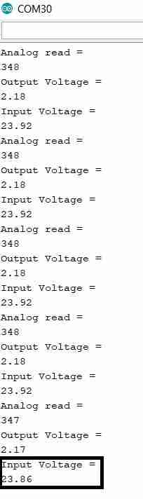
Serial.println("Analog read = ");
Serial.println(value);
Serial.println("Output Voltage = ");
Serial.println(vout);
Serial.println("Input Voltage = ");
Serial.println(vin);
if(vin>24.50) {digitalWrite(a,HIGH);}
else { digitalWrite(a,LOW);}
if(vin<=24.50 && vin>23.50) {digitalWrite(b,HIGH);}
else { digitalWrite(b,LOW);}
if(vin<=23.50 && vin>22.50) {digitalWrite(c,HIGH);}
else { digitalWrite(c,LOW);}
if(vin<=22.50 && vin>21.50) {digitalWrite(d,HIGH);}
else { digitalWrite(d,LOW);}
if(vin<=21.50 && vin>20.50){digitalWrite(e,HIGH);}
else {digitalWrite(e,LOW);}
if(vin<=20.50) {digitalWrite(f,HIGH);}
else {digitalWrite(f,LOW);}
delay(2000);
}
Calibration of the circuit
The circuit needs to be calibrated to find the right value of the resistance from the potentiometer which gives the same voltage as the serial monitor on the Arduino. For this purpose:
- we use a variable dc power supply and set it to 24.9 V.
- We rotate the potentiometer until the serial monitor shows close to 24.9 V. Once it does, we leave the potentiometer to this setting.
- We would find that now if we change the variable dc power supply to another voltage, the serial monitor also shows a voltage close to this value.
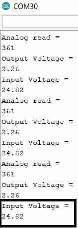
We see that the voltage shown in the display of the variable dc power supply and the serial monitor matches closely.
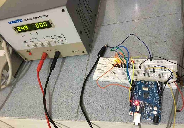
Hence, the calibration has been done and now we won’t change the potentiometer setting.
Test with Lithium Ion Battery
Here, we have connected the Li ion battery to our circuit.
The battery voltage reading is between 23.6 V and 23.7 V.
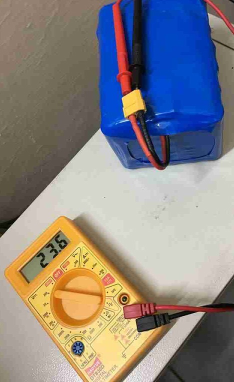
The serial monitor shows the value of the battery voltage to be 23. 8 V which is close.
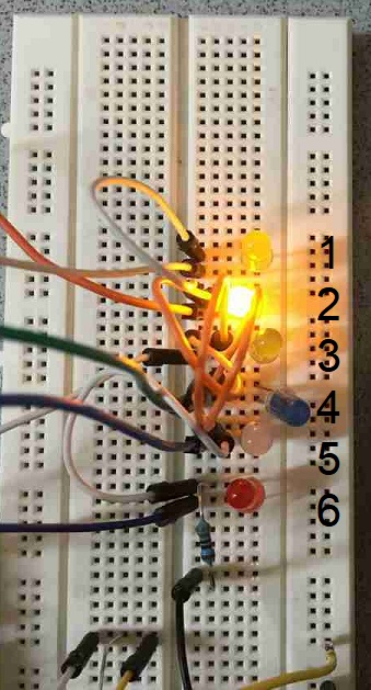
This leads to lighting up of the 2nd LED showing that the charge in the battery is between 60% to 80%.
Current sensing
I took guidance from this article.
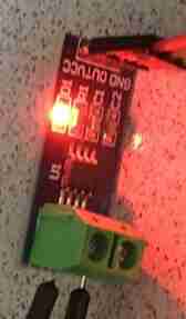
This image shows the close up of ACS712 30 A module.
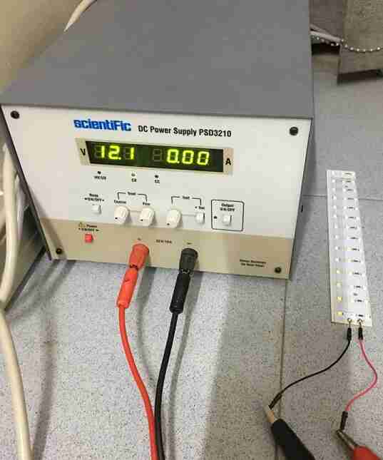
This is the basic wiring with Arduino.
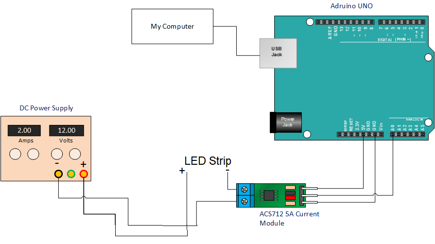
This is the setup of testing 12 V LED strip with variables DC power supply.
This is the Arduino code:
//http://henrysbench.capnfatz.com/henrys-bench/arduino-current-measurements/the-acs712-current-sensor-with-an-arduino/
/*
Measuring Current Using ACS712
*/
const int analogIn = A0;
int mVperAmp = 66; // use 100 for 20A Module and 66 for 30A Module and 185 for 5A module
int RawValue= 0;
int ACSoffset = 2500;
double Voltage = 0;
double Amps = 0;

void setup(){
 Serial.begin(9600);
}

void loop(){

 RawValue = analogRead(analogIn);
 Voltage = (RawValue / 1024.0) * 5000; // Gets you mV
 Amps = ((Voltage - ACSoffset) / mVperAmp);


 Serial.print("Raw Value = " ); // shows pre-scaled value
 Serial.print(RawValue);
 Serial.print("\t mV = "); // shows the voltage measured
 Serial.print(Voltage,3); // the '3' after voltage allows you to display 3 digits after decimal point
 Serial.print("\t Amps = "); // shows the voltage measured
 Serial.println(Amps,3); // the '3' after voltage allows you to display 3 digits after decimal point
 delay(2500);

}
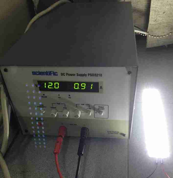
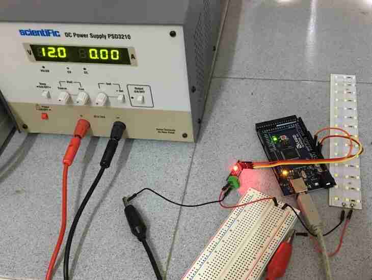
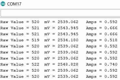
This shows the test setup in action.
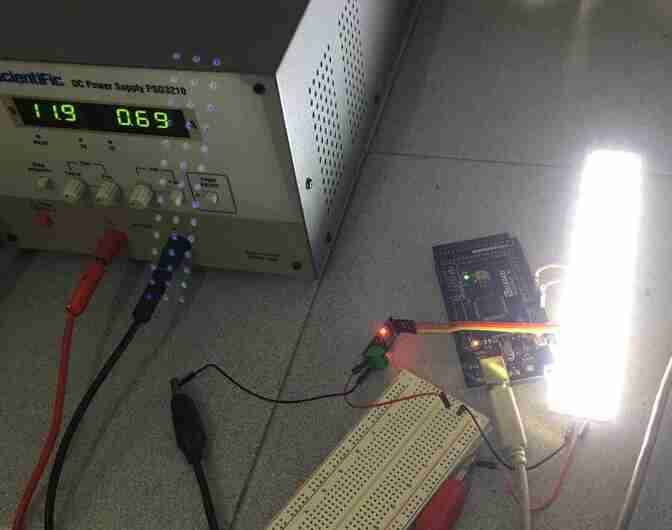
The serial monitor shows that the current shown on the dc power supply is close to the current sensed on the serial monitor.
Horn
For the horn, I thought of using the regular bicycle bell.
Datasheets
MOSFETs
IRF540N can go upto 100 V, 33A.
IRF9540N can go upto 100 v, 23A.
IRFZ44N can go upto 55 V, 49 A.
Assembly of components
Since I have tested all the components working individually, now I wanted to bring them together.
Connecting the PWM motor and the throttle
The Arduino code for connecting PWM motor with throttle:
// pin number 9 for motor
// analog pin a0 for reading throttle value

int pwm_motor = 9;           // the PWM pin dc motor is attached to

void setup() {
  Serial.begin(9600);
  // declare pin 9 to be an output:
  pinMode(pwm_motor, OUTPUT);

}

void loop() {
  // read the throttle input on analog pin 0:
  int sensorValue = analogRead(A0);

  if (sensorValue < 168) {sensorValue = 168;}
  if (sensorValue > 882) {sensorValue = 882;}
  sensorValue = map(sensorValue, 168, 882, 0, 255);

  // print out the value you read:
  Serial.println(sensorValue);
  delay(1000);        // delay in between reads for stability

  analogWrite(pwm_motor, sensorValue);
  // wait for 30 milliseconds to see the dimming effect
  delay(30);

}
The connections are as follows:
Relay
In order to add brakes, I need to be able to stop the motor when the brakes are applied. I got guidance from this article on how to add a relay to my circuit to act as an electrical switch.
I used this transistor PN2222A to activate my relay when needed to power on or power off a load.
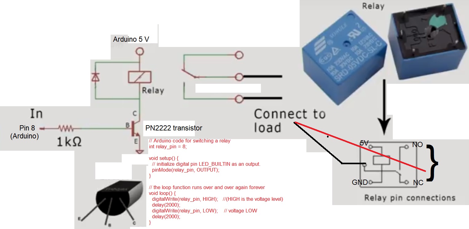
The circuit implemented on a 12 V LED strip load with Arduino switched the LED strip on and off every 2 seconds. One can also hear the relay switching sound.
Connecting DC motor, throttle with brakes and ignition switch
It turns out that I don’t need a relay after all. With smart Arduino code logic, I did away with needing a relay. The Arduino code:
// pin number 9 for motor
// analog pin a0 for reading throttle value

int ignition_pin = 5;
//int brake_left_pin = 6;
int brake_right_pin = 7;
int pwm_motor = 9;           // the PWM pin dc motor is attached to

int led_pin = 13;

void setup() {
  Serial.begin(9600);

  pinMode(led_pin, OUTPUT);
  pinMode(ignition_pin, INPUT_PULLUP);
  //pinMode(brake_left_pin, INPUT_PULLUP);
  pinMode(brake_right_pin, INPUT_PULLUP);
  pinMode(pwm_motor, OUTPUT);
}

void loop() {

    if (/*(digitalRead(brake_left_pin) == LOW) || */(digitalRead(brake_right_pin) == LOW) || (digitalRead(ignition_pin) == HIGH))// brake press or ignition off
    {
      digitalWrite(led_pin, HIGH);   //(HIGH is the voltage level)
      delay(100);
    }
    else
    {
      digitalWrite(led_pin, LOW);   //(LOW is the voltage level)
      delay(100);
  // read the throttle input on analog pin 0:
  int sensorValue = analogRead(A0);

  if (sensorValue < 168) {sensorValue = 168;}
  if (sensorValue > 882) {sensorValue = 882;}
  sensorValue = map(sensorValue, 168, 882, 0, 255);

  // print out the value you read:
  //Serial.println(sensorValue);
  //delay(1000);        // delay in between reads for stability

  analogWrite(pwm_motor, sensorValue);
  // wait for 30 milliseconds to see the dimming effect
  delay(30);
    }
}
Motor and LED strip controller on my own PCB
I wanted to power a 24 V DC motor and 24 V LED strip to be used as headlight for my project. I used PWM using IRLZ44N MOSFET and ATtiny44 uC to power these loads. I kept the digital and power boards separate.
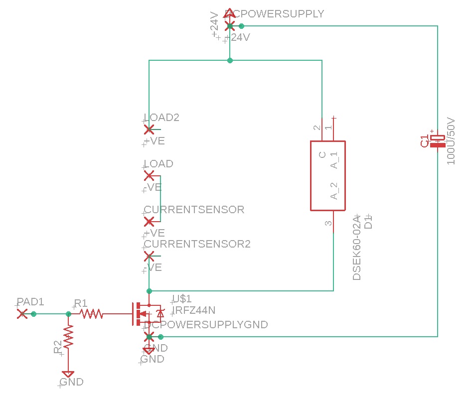
PWM motor control with N channel Mosfet
The 24 V PMDC motor and the 24 V LED strip can be controlled using the PWM signal from the uC. The PWM channel can be amplified using an N channel Mosfet.
I got the schematic of this circuit from google images and then modified it for my needs.
The MOSFET used was IRLZ44N
The Schottky diode used was IN5819.
The fade LED code was used to increase and decrease the speed of the motor with PWM signals.
/*
  Fade

  This example shows how to fade an LED on pin 9 using the analogWrite()
  function.

  The analogWrite() function uses PWM, so if you want to change the pin you're
  using, be sure to use another PWM capable pin. On most Arduino, the PWM pins
  are identified with a "~" sign, like ~3, ~5, ~6, ~9, ~10 and ~11.

  This example code is in the public domain.

  http://www.arduino.cc/en/Tutorial/Fade
*/

int led = 3;           // the PWM pin the LED is attached to
int brightness = 0;    // how bright the LED is
int fadeAmount = 5;    // how many points to fade the LED by

// the setup routine runs once when you press reset:
void setup() {
  // declare pin 3 to be an output:
  pinMode(led, OUTPUT);
}

// the loop routine runs over and over again forever:
void loop() {
  // set the brightness of pin 3:
  analogWrite(led, brightness);

  // change the brightness for next time through the loop:
  brightness = brightness + fadeAmount;

  // reverse the direction of the fading at the ends of the fade:
  if (brightness <= 0 || brightness >= 255) {
    fadeAmount = -fadeAmount;
  }
  // wait for 30 milliseconds to see the dimming effect
  delay(30);
}
This circuit can also be connected to a battery in place of a dc power supply. This circuit can be extended to integrate with the throttle.
Digital board
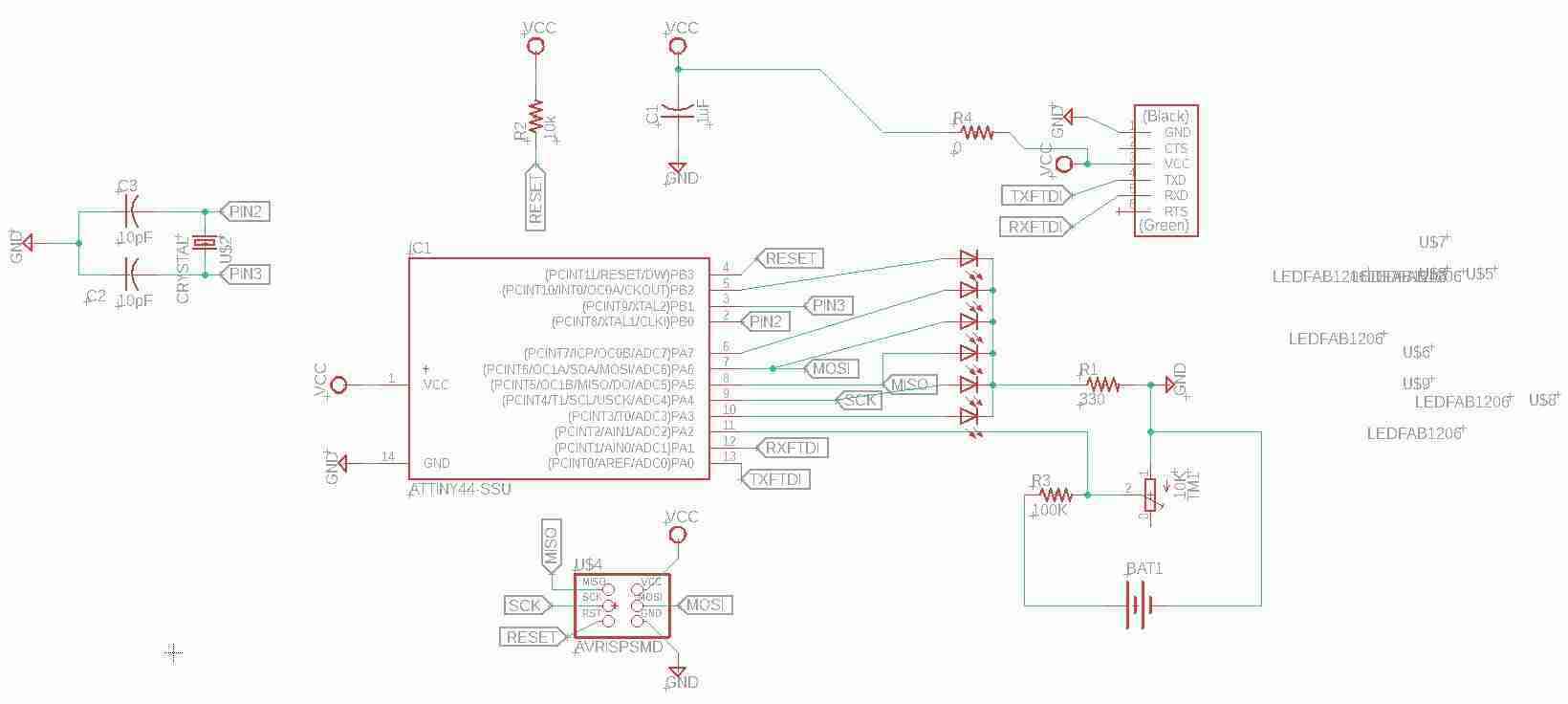
This is the schematic of the ATTiny44 digital board used for PWM.
This is the layout of the ATTiny44 digital board used for PWM.
This is the exported png from Eagle for traces to be milled on Roland’s SRM-20.
This is the outline to be cut on Roland’s SRM-20.

This is the ATtiny44 digital board in action.
Power board
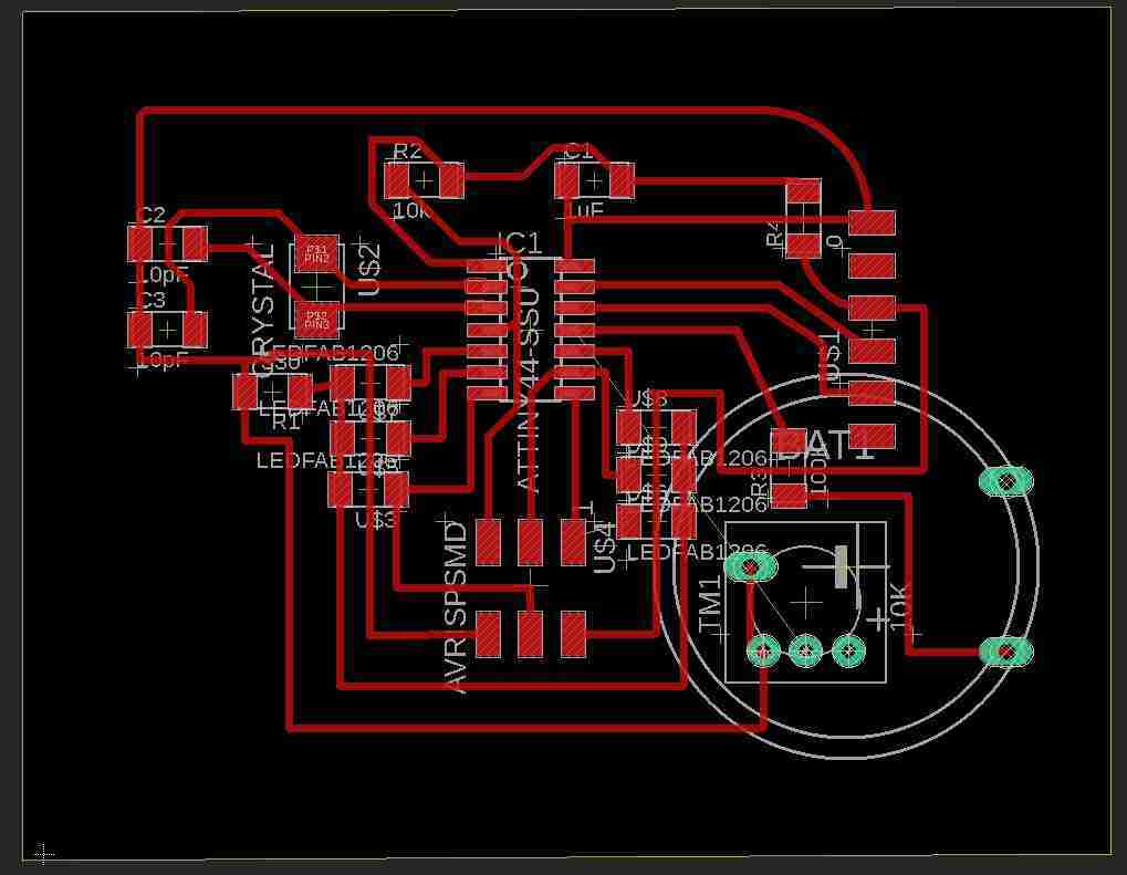
This is the schematic of the power board.
I used a trace width calculator to calculate the trace width for my circuit.
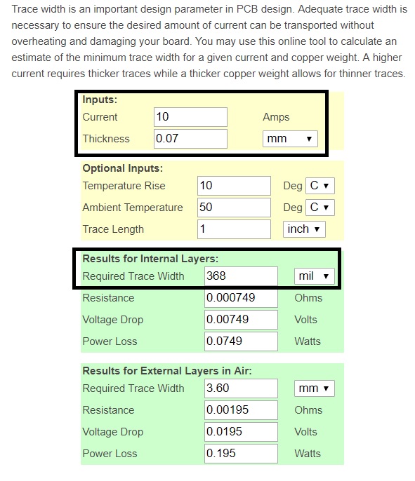
The trace width came out to be 368 mil for the internal layers. I used a trace width of 400 mil everywhere except the dc power supply as there wasn’t enough length available to place the traces. If I increased the length of traces then the board became too big to create an rml file on fabmodules.
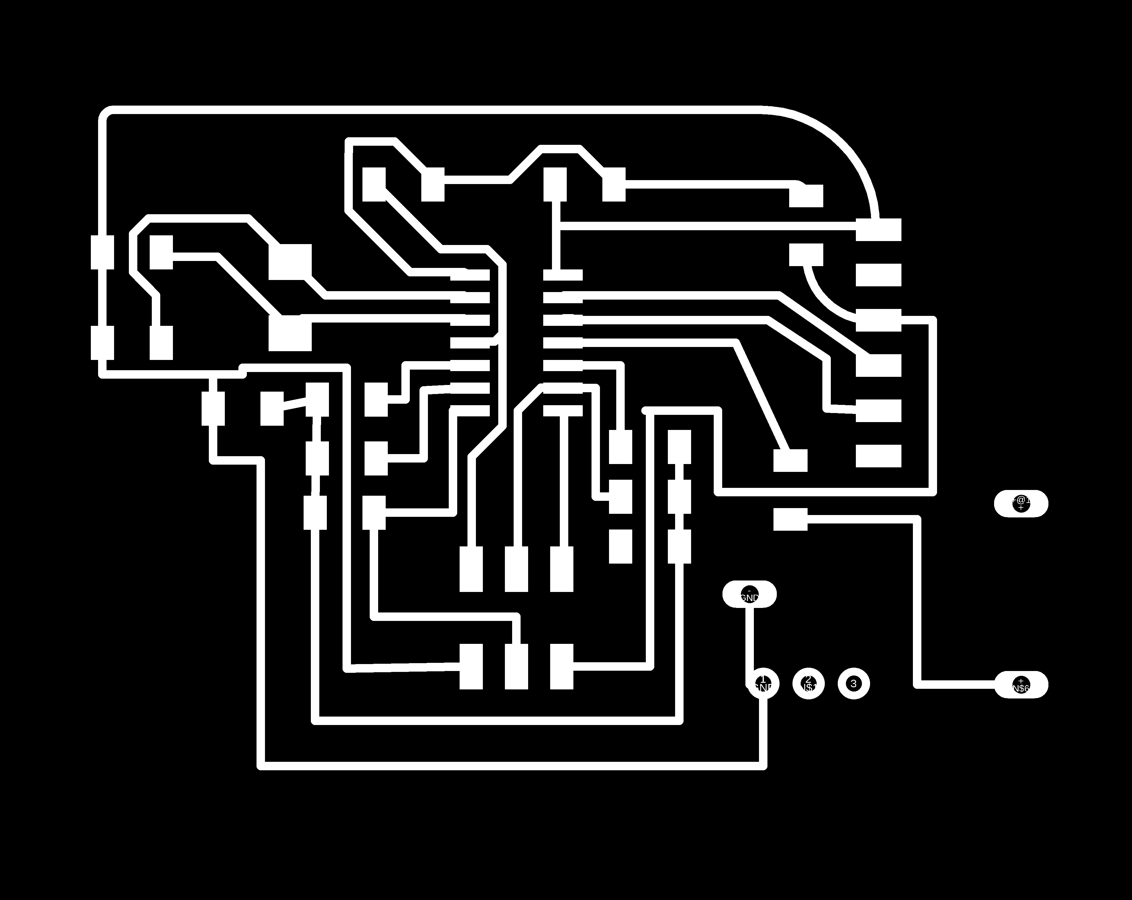
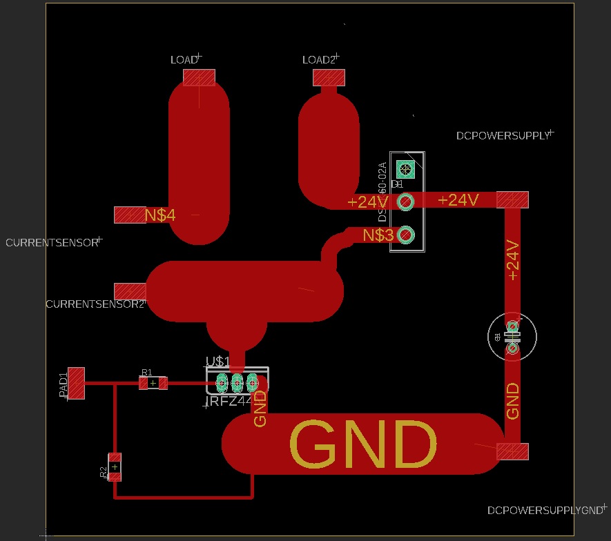
With this trace width, this was the resulting layout.
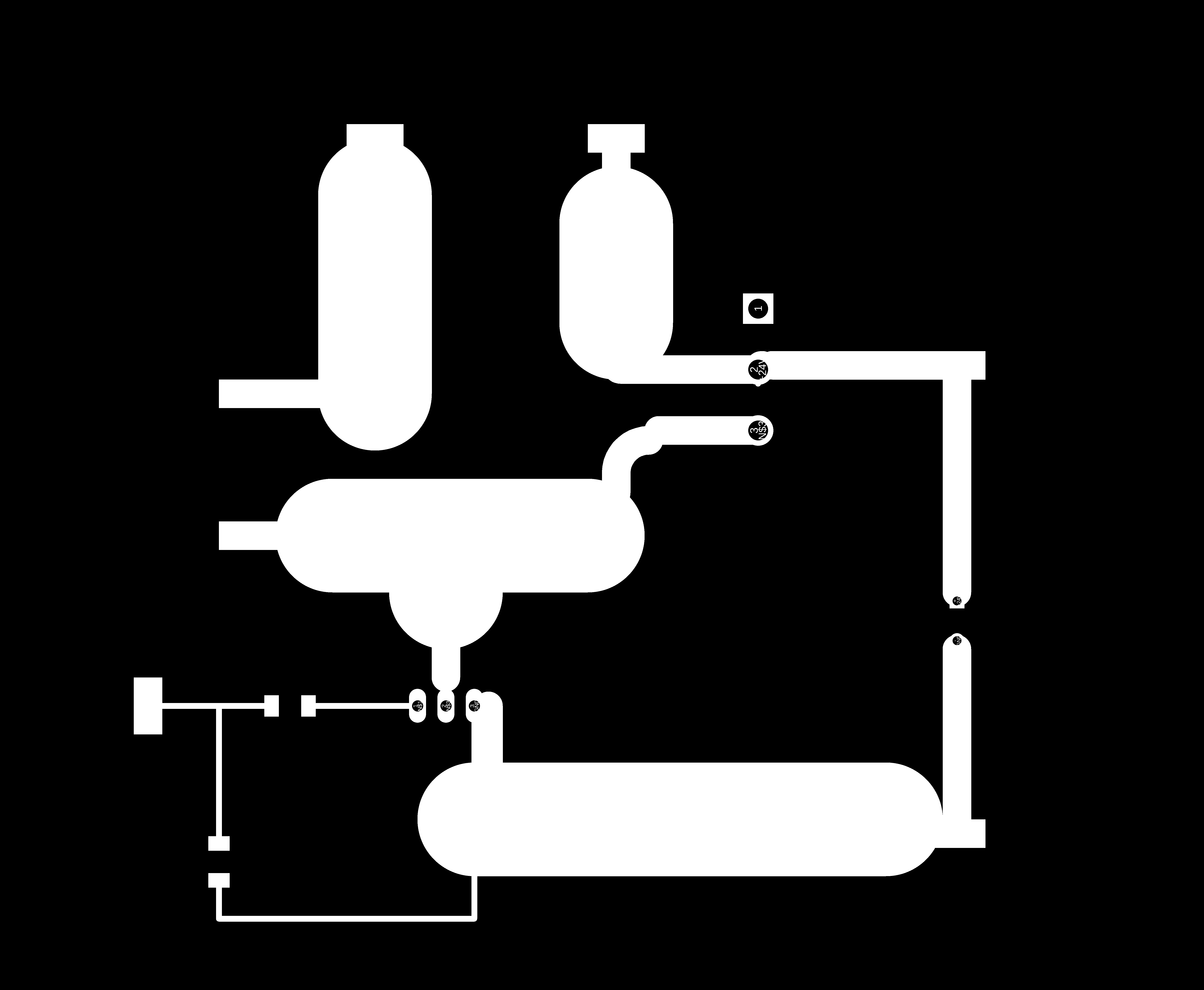
This was the png for traces which was used to create an rml file for milling the pcb.
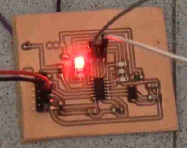
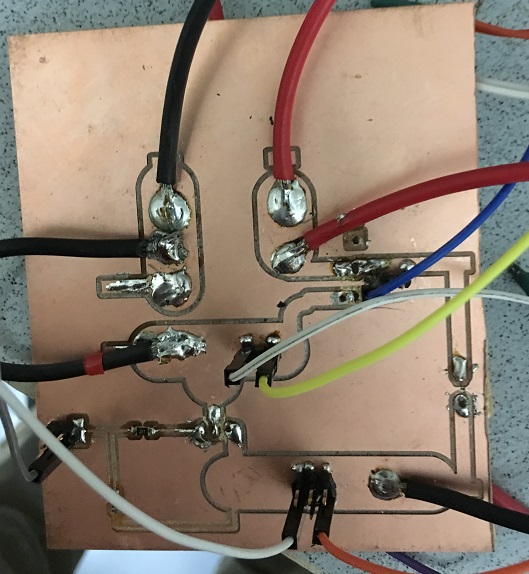
This is the power board in action.
The MOSFET and the diode were connected in a perf board as per the image below as I wasn’t able to solder them properly on the PCB.
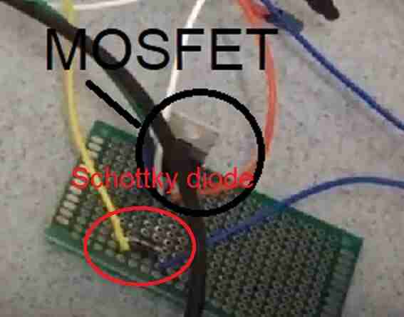
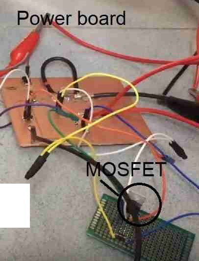
This shows the MOSFET and the power board together.
Problems faced and fixes
The below image shows the different connections in the circuit.
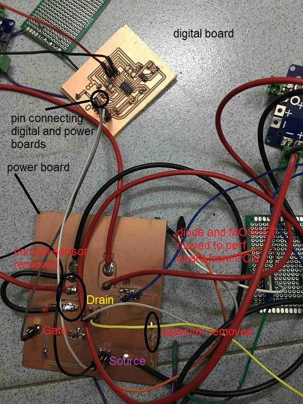
Problems and fixes:
-
This was the first time I was working with a power board and was a bit cautious as it involved 10 Amps or more of current. During my testing, I realized that my circuit stopped working when I attached the 470 uF capacitor in parallel to the 24 V DC power supply. May be the circuit was busy charging the capacitor as the capacitance was oversized. So, I removed the capacitor and the circuit started working.
-
The current sensor was also causing problems with the circuit so I removed that also to further simplify the circuit.
-
I also had to place the MOSFET and the diode through hole components to a perf board as when I soldered them on the single sided PCB, the circuit wouldn’t work.
PWM with LED strip
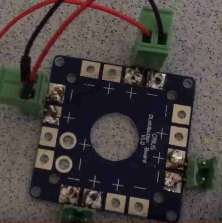
I used a power distrubtion board since I needed to supply 24 V to 24 V LED strip, 24 V DC motor and battery monitor circuit.
I also made a LM7805 circuit using a 9V battery to have a 5 V power supply for the ATtiny44.
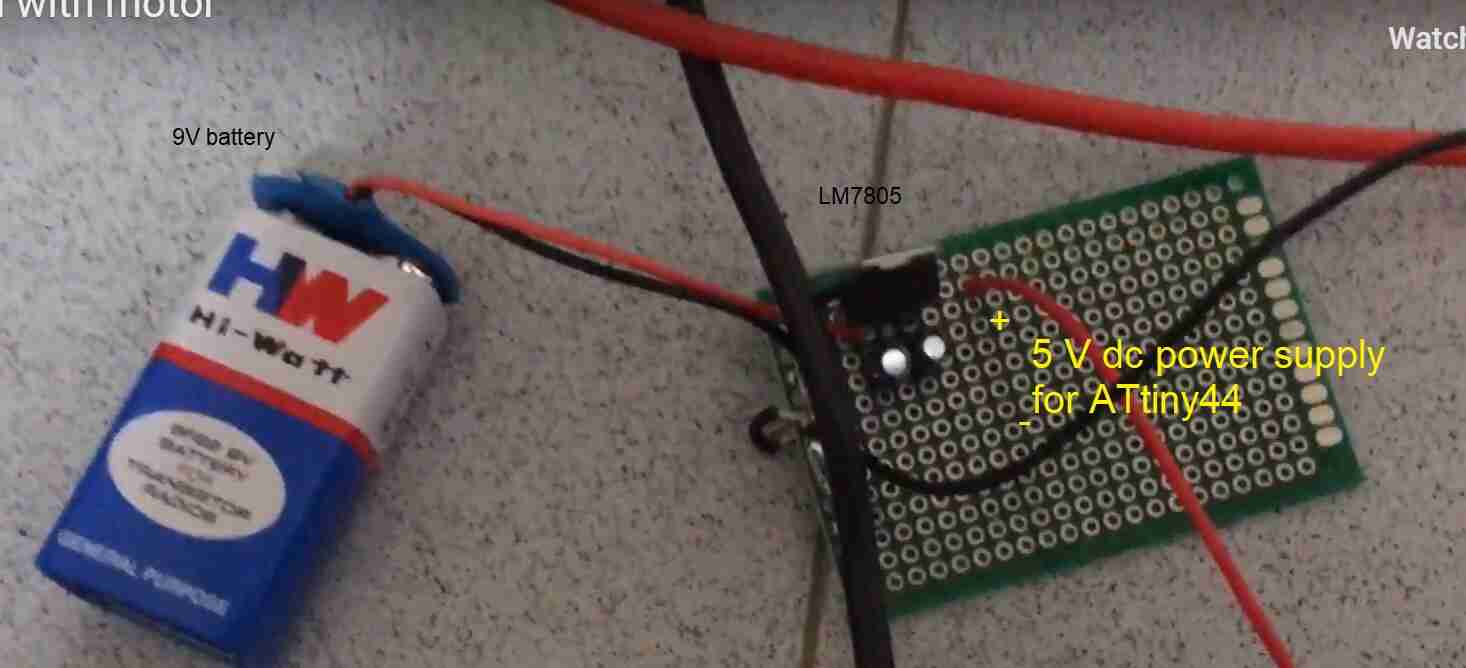
This shows the connections for this 24 V LED strip circuit.
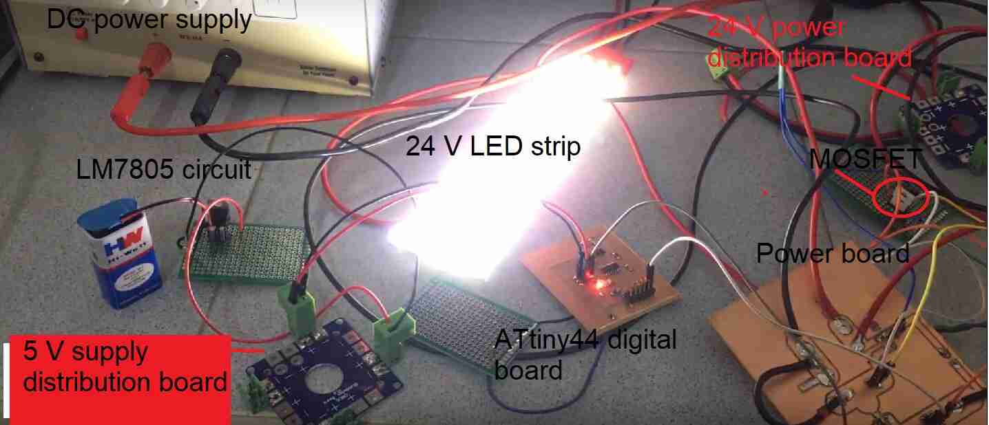
And this shows the fruit of hard work finaly. The LED strip running on the PWM code for fading in all its glory.
The arduino code used for the above circuit:
int led = 5;           // the PWM pin the LED is attached to
int brightness = 0;    // how bright the LED is
int fadeAmount = 5;    // how many points to fade the LED by

// the setup routine runs once when you press reset:
void setup() {
  // declare pin 9 to be an output:
  pinMode(led, OUTPUT);
}

// the loop routine runs over and over again forever:
void loop() {
  // set the brightness of pin 9:
  analogWrite(led, brightness);

  // change the brightness for next time through the loop:
  brightness = brightness + fadeAmount;

  // reverse the direction of the fading at the ends of the fade:
  if (brightness <= 0 || brightness >= 255) {
    fadeAmount = -fadeAmount;
  }
  // wait for 30 milliseconds to see the dimming effect
  delay(30);
}
PWM with DC motor
This shows the connections for this 24 V DC motor circuit.
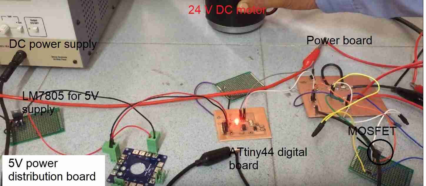
And this shows the fruit of hard work. The DC motor running on the simple PWM code for fading.
Please note that the digital and the power boards were the same for the DC motor and the LED strip although I milled two each to use them together in my bike.
Composite sun shade
This shows how the composite sun shade would extend from the solar panel to prevent heat from getting to the rider as well be light weight.
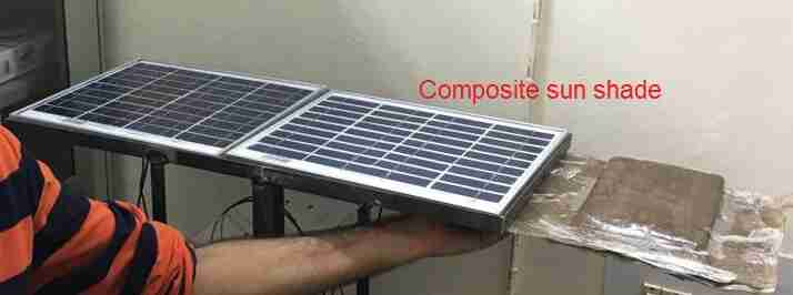
Further details on how this was made can be found in the wildcard week assignment on composites.
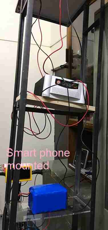
Smartphone bike mount
The smart phone bike mount would have the smart phone on it for directions as well as to add a Mobile App which can be used to sense data and actuation. For instance, we can know the charge remaining with the battery or the current drawn by the motor.
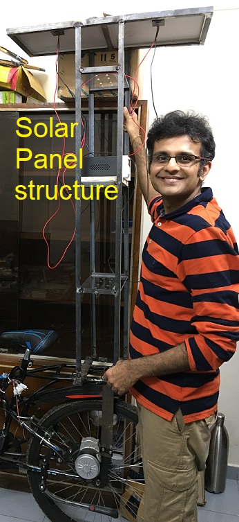
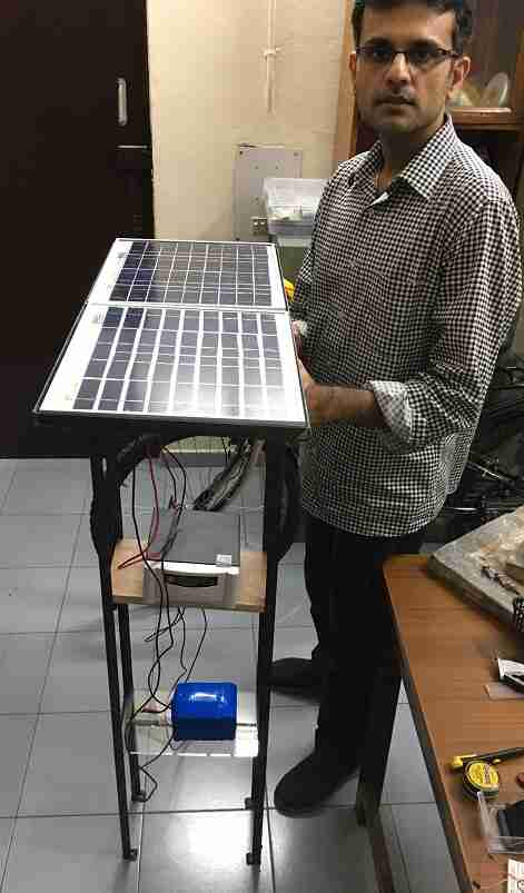
Solar panel stand
This is the stand for carrying the solar panel on the bike.
Summary slide and video for 17th June 2019
I have presented my summary slide and a video for my project. The slide is present at:
The video can be viewed at:
Design files
Download for the pcb related files for all the boards milled.
Download for the CAD for mold for making composite sun shade.
Download for the CAD for smart phone bike mount, PCB casing CAD and arduino code for connecting the bike components with 24 V DC motor loads.
Acknowledgements
I would like to thank Neil and entire central coordination of Fab Academy for making this journey memorable for us. I am better equipped now with the skills and so looking forward to making things which can make this world a better place.
I would also like to thank our remote instructor Puneeth, local instructor Rahul and Fab Lab manager Darshan for their support.
I would like to thank my wife Payal for putting up with me for the last 6 months when I juggled between work and Fab Academy and I couldn’t spend enough time with her. Over and above this, when I was working from my office, she was there besides me whenever I needed her.
I would also like to thank Supreme Bike shop, Green Park, New Delhi mechanics who helped in the assembly of the motor on the bike.
I would also like to thank Satish and Hasmuddin for helping with the making of the welded solar panel stand.
Integration
Summary
I took this project as a long term undertaking and hence, it operated at different levels. On one hand, I created the framework of solar powered e-bike. I got the frame for the solar panels made and fabricated the composite sun shade. Please note that the frame for mounting the solar panels is detachable and can be removed when not needed. I also connected the solar panel to the battery for charging. On the other hand, for the time frame of fab academy, I focussed on making my own PCB based PWM controller for making the bike’s components i.e. DC motor, LED strip, brakes, ignition switch and throttle work together. I also made a smart phone bike mount which could be connected to the bike’s electronics for enhancing the capabilities. I have also worked out a battery monitor and current sensing on Arduino which could be further integrated with the e-bike kit.
Bike level layout
This shows all the components on the bike.
This shows the back side view of the bike.
The circuit would be kept close to the carrier.
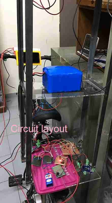
The solar panel on the frame.
These are the integration videos. This video shows LED PWM with everything on the bike. Please note that the battery was discharged so power is being supplied by the variable dc power supply.
This video shows the PWM with the motor which is installed on the bike.
I am working now to integrate the brakes, throttle, ignition switch with the DC motor. I am also making a case for carrying the PCBs. Once I integrate and make everything weather proof, I am looking forward to test drive the bike :).
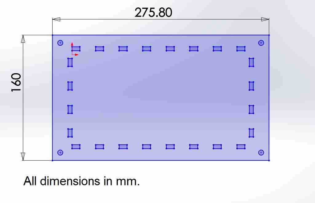
Case for PCB
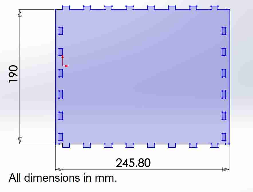
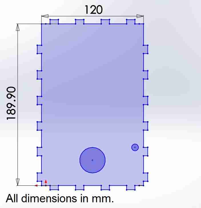
I used Solidworks to make the CAD of press fit acrylic case for my PCB circuit. This was cut using the laser cutter. The measurements were as per the space available on the carrier of the bike.
The below images are for the top and the bottom plate of the case. The bottom plate has a thickness of 10 mm for extra strength and the top plate and the walls of this case have a thickness of 5 mm.
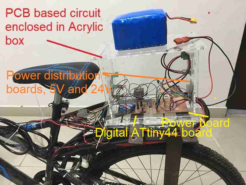
This is how the enclosed circuit looks like. The bigger box have allowed me to stick part of circuit on the side walls as well. The power board which connects the DC motor and the LED strip has been kept at the back side of the carrier and connects the Lithium Ion battery which is the power supply.
The ATtiny44 digital board has been kept towards the front of the carrier and takes the connections from the throttle, brakes and the ignition switch.
The power distribution boards have been hung on the side walls.
Final project
I am really excited to share this video of the working of LED strip with the throttle, brakes and ignition switch. Please note that I have first used LED strip as the load instead of the DC motor as it is easier to debug in a place and has a lower Ampere requirement. All the components of the bike work as expected with the 24 V LED strip load.
This is the code used. The circuit to have been implemented on the ATTiny44 digital board. The brakes, ignition and pwm signal motor have been given digital pins. The throttle takes analog input. When the ignition switch is off or brakes are pressed, the load stops. When ignition switch is on or none of the brakes are pressed, the throttle can be used for PWM of the LED strip.
// combining throttle with pwm motor ctrl
//throttle check with multimeter and 5V dc supply
//https://www.youtube.com/watch?v=GDnI4HA_QyY


// pin number 9 for motor
// analog pin a0 for reading throttle value

int brake_left_pin = 7;
int brake_right_pin = 8;
int ignition_pin = 4;
//throttle is pin 5.
int pwm_motor = 6;           // the PWM pin dc motor is attached to

int led_pin = 3;

void setup() {
  //Serial.begin(9600);

  pinMode(led_pin, OUTPUT);
  pinMode(ignition_pin, INPUT_PULLUP);
  pinMode(brake_left_pin, INPUT_PULLUP);
  pinMode(brake_right_pin, INPUT_PULLUP);
  pinMode(pwm_motor, OUTPUT);
}

void loop() {

    if ((digitalRead(brake_left_pin) == LOW) || (digitalRead(brake_right_pin) == LOW) || (digitalRead(ignition_pin) == HIGH))// brake press or ignition off
    {
      digitalWrite(led_pin, HIGH);   //(HIGH is the voltage level)
      analogWrite(pwm_motor, 0);
      delay(100);
    }
    else
    {
      digitalWrite(led_pin, LOW);   //(LOW is the voltage level)
      delay(100);
  // read the throttle input on analog pin 0:
  int sensorValue = analogRead(A5);

  if (sensorValue < 168) {sensorValue = 168;}
  if (sensorValue > 882) {sensorValue = 882;}
  sensorValue = map(sensorValue, 168, 882, 0, 255);

  // print out the value you read:
  //Serial.println(sensorValue);
  //delay(1000);        // delay in between reads for stability

  analogWrite(pwm_motor, sensorValue);
  // wait for 30 milliseconds to see the dimming effect
  delay(30);
    }
}
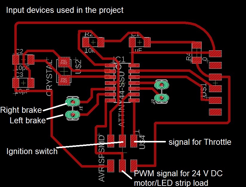
Input devices used
This PCB layout shows the input devices used in the project i.e. throttle, brakes and ignition switch.
Output devices used
The output devices were 24 V DC motor and 24 V LED strip. The details of the power board are given in one of the sections above.
Test run
I am ready in the corridor of my office for test runs.
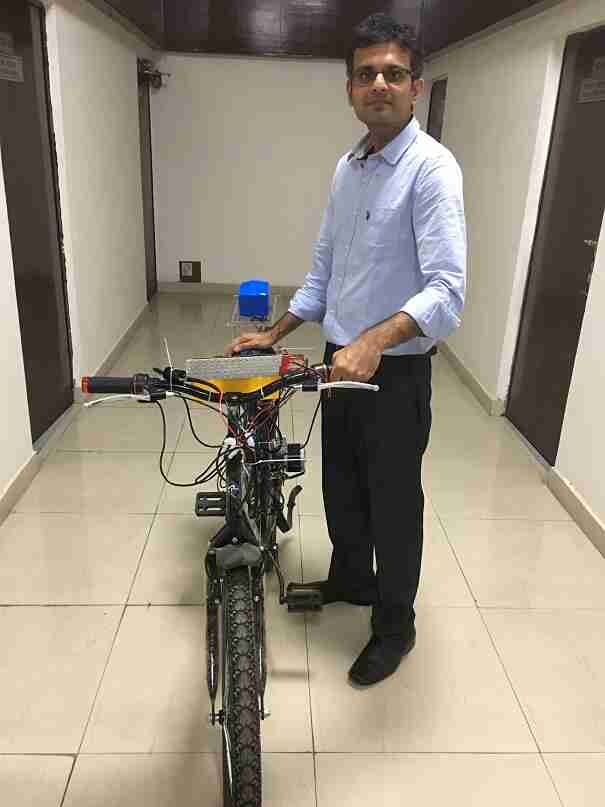
In the video, first I connect the 24 V battery to the circuit. Then I start the bike with the ignition switch. We do see the 3d printed smart phone mount in the view. I rotate the throttle and see the LED strip getting dimmer or brighter due to the PWM signal. We also see that the LED strip turning off as soon as left or the right brakes are pressed irrespective of the throttle being pressed or not. We also see that the throttle doesn’t have any effect if the ignition switch is turned off.
I also tried to make the DC motor work with this circuit with the battery but the thinner wires in the circuit blew away due to high ampere current and I have to fix that. Until now, I had made the circuit work with the DC motor using DC power supply while limiting the current to 2.5 A so it worked fine.
Final Video and Summary
The video shows my journey of this project. The first spiral was working on a purchased kit and making it work. I also understood how different components of the bike worked and interacted with each other. I made them work using Arduino Uno first. Next I used PWM to run 24 V LED strip and DC motor loads. For digital board, I used ATtiny44 and made by own power board. Then, I connected all my bike components with the 24 V LEd strip to show their working and interactions. I also made a composite sun shade and smart phone bike mount along the way.
The future directions of this work are to make DC motor work with the bike components, optimize the circuit for compactness, make a battery monitor and integrate the solar panel with my PCB.
The skills that I used in this project were:
Own PCB circuit design and fabrication and embedded programming for a digital ATtiny44 and a power board and the connections. Making a 24 V DC motor and LED strip load run interact with bike components such as brakes, ignition switch and throttle electronically. Use of laser cutting for making a press fit casing of the PCB case, 3D printing for smart phone bike mount and molding and composite sun shade making.
It has been very satifying so far and this is a project which I would keep working on. I also hope that this work inspires others also to take up projects in this domain and accelerate the acceptance of solar powered electric vehicles in our lives and make the planet greener!
License

Solar powered electric bike con kit by Jay Dhariwal is licensed under a Creative Commons Attribution 4.0 International License