14. Networking and communications (Apr 30)
This week we were suggested to send a message between two projects (assignments made by different students) as a part of the group assignment. For the individual assignment, we were supposed to design, build and connect wired or wireless nodes with network or bus addresses.
Arduino based network
I was excited at the thought of connecting two or more separate uC based pcbs. For one, it would allow me to make my pcbs modular as is the case for using functions in programming to make the code more readable. I started with connecting Arduinos together.
i2c protocol
I had heard of the i2c communications protocol which can connect upto 112 devices. i2c protocol is also easy to implement. It involves making one of the nodes as masters and the rest as slaves. I implemented it for 3 Arduino Unos. I used the advice from this video with the links for the codes for the master and the code for the slave.
The code for the master was:
#include <Wire.h>

void setup()
{
  Wire.begin();
}

void loop()
{
  Wire.beginTransmission(1);
  Wire.write('H');
  Wire.endTransmission();

  delay(500);

  Wire.beginTransmission(1);
  Wire.write('L');
  Wire.endTransmission();

  delay(500);

  Wire.beginTransmission(2);
  Wire.write('H');
  Wire.endTransmission();

  delay(500);

  Wire.beginTransmission(2);
  Wire.write('L');
  Wire.endTransmission();

  delay(500);
}
This code uses a library called Wire. It has two slaves with slave id of 1 and 2. The master sends a character ‘H’ for high and a character ‘L’ for low to each of the slaves one after the other.
The code for slave 1 was:
#include <Wire.h>

const byte slaveId = 1;

void setup()
{
  Wire.begin(slaveId);
  Wire.onReceive(receiveEvent);

  pinMode(13,OUTPUT);
  digitalWrite(13,LOW);
}

void loop()
{
}

void receiveEvent(int howMany)
{
  char inChar;

  while(Wire.available() > 0)
  {
    inChar = Wire.read();

    if (inChar == 'H')
    {
      digitalWrite(13, HIGH);
    }
    else if (inChar == 'L')
    {
      digitalWrite(13, LOW);
    }
  }
}
Slave 1 lights up the inbuilt LED 13 when it receives the character ‘H’.
The code for slave 2:
#include <Wire.h>

const byte slaveId = 2;

void setup()
{
  Wire.begin(slaveId);
  Wire.onReceive(receiveEvent);

  pinMode(13,OUTPUT);
  digitalWrite(13,LOW);
}

void loop()
{
}

void receiveEvent(int howMany)
{
  char inChar;

  while(Wire.available() > 0)
  {
    inChar = Wire.read();

    if (inChar == 'H')
    {
      digitalWrite(13, HIGH);
    }
    else if (inChar == 'L')
    {
      digitalWrite(13, LOW);
    }
  }
}
Slave 2 lights up the inbuilt LED 13 when it receives the character ‘H’.
This image shows the connections, which are simple. All the SCL pins on A4, SDA pins on A5 and ground pins are connected together.
The video shows the LED 13 blinking on slave 1 and slave 2 alternately.
i2c protocol with attiny44 boards
I wanted to extend i2c communication with two of my attiny44 boards. It was easy to find the Wire library connecting 3 Arduino Unos. But tt was very difficult to find Arduino libraries to hook up ATtiny44 boards using i2c protocol. There were libraries to connect ATtiny85 but not for ATTiny44. After seraching for some time, I found some advice from a fab academy student. This advice was also a good read.
He had suggested to make connections as per this diagram, adding 10 K resistors between MOSI and SCK pins as shown:
I downloaded TinyWireS library for the slave and USIWire.rar library from his page for the master nodes.
The code uploaded for the Master node was:
#include <USIWire.h>                 // I2C Master lib for ATTinys which use USI

#define ADDR   0x26
#define LED1_PIN         7              // ATtiny Pin 3

int rec=0;

void setup(){
  pinMode(LED1_PIN,OUTPUT);


  Wire.begin();                    // initialize I2C lib
  Blink(LED1_PIN,2);                    // show it's alive
  delay (1000);
}


void loop(){
   Wire.beginTransmission(ADDR);
   Wire.write(B00000001);            // Send 1 byte
   Wire.endTransmission();
   Blink(LED1_PIN,2);               // show it's alive and sending
  delay (1000);                    // wait a few sec before next reading
}

void Blink(byte led, byte times){ // poor man's GUI
  for (byte i=0; i< times; i++){
    digitalWrite(led,HIGH);
    delay (400);
    digitalWrite(led,LOW);
    delay (175);
  }
}
The code uploaded for the slave node was:
#include "TinyWireS.h"                  // wrapper class for I2C slave routines

#define I2C_SLAVE_ADDR  0x26            // i2c slave address (38)
#define LED1_PIN         7              // ATtiny Pin 3
#define LED2_PIN         8              // ATtiny Pin 6

void setup(){
  pinMode(LED1_PIN,OUTPUT);             // for general DEBUG use
  pinMode(LED2_PIN,OUTPUT);             // for verification
  digitalWrite(7, HIGH);              // turn the LED on (HIGH is the voltage level)
  delay(1000);                       // wait for a second
  digitalWrite(7, LOW);              // turn the LED off by making the voltage LOW
  TinyWireS.begin(I2C_SLAVE_ADDR);      // init I2C Slave mode
  delay(1000);                          // wait for a second
}


void loop(){
  byte byteRcvd = 0;
  if (TinyWireS.available()){           // got I2C input!
    byteRcvd = TinyWireS.receive();     // get the byte from master
   // byteRcvd += 10;                     // add 10 to what's received
   // TinyWireS.send(byteRcvd);           // send it back to master

    digitalWrite(7, HIGH);    //alive
    delay(2000);
    digitalWrite(7, LOW);
    delay(2000);

  if(byteRcvd!=0){
    digitalWrite(8, HIGH);     //blue led= receive
    delay(2000);
    //digitalWrite(8, LOW);
    //delay(2000);
  }
  }

}
The connections on my ATTiny44 boards looked like:
But I couldn’t get it to work after several tries.
Bluetooth wireless communication
Bluetooth with Arduino
I have also used Bluetooth HC-05 module to connect to a Mobile App developed by me using MIT App Inventor. I have detailed this out in the Interface and Application Programming week but I am sharing the demo video here as well:
The connections between Arduino and Bluetooth module were as follows:
Bluetooth with ATtiny44
I then integrated Bluetooth module HC-05 with ATTiny44. The connections were pretty basic and the same as done above. The below image shows the setup of connecting the Bluetooh HC-05 module, ATtiny44, Nexus 6P Android phone App with the power supply.
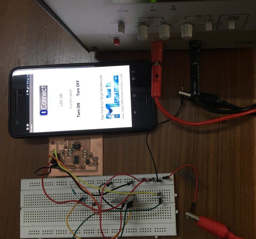
The following code was used for this demo. One of the LEDs on pin 6 switches on as soon as power supply is received by the ATTiny44 board. The LEDs on pin3 and pin4 toggle depending on whether the “Turn on” or “Turn off” is pressed on the Mobile App.
#include <SoftwareSerial.h>

int ledPin = 6; // physical pin 5 on attiny44

int ledPin1 = 3;
int ledPin2 = 4;

#define RX    0   // physical pin 13 on attiny44
#define TX    1   // physical pin 12 on attiny44

SoftwareSerial mySerial =  SoftwareSerial(RX, TX);

int state = 0;

void setup() {
  pinMode(ledPin, OUTPUT);
  pinMode(ledPin1, OUTPUT);
  pinMode(ledPin2, OUTPUT);
  digitalWrite(ledPin, HIGH);
  digitalWrite(ledPin1, LOW);
  digitalWrite(ledPin2, LOW);
  mySerial.begin(9600); // Default communication rate of the Bluetooth module
}

void loop() {

  digitalWrite(ledPin, HIGH); // Turn LED OFF

  if(mySerial.available() > 0){ // Checks whether data is comming from the serial port
    state = mySerial.read(); // Reads the data from the serial port
 }
 if (state == '0') {
  digitalWrite(ledPin1, LOW); // Turn LED OFF
  digitalWrite(ledPin2, HIGH); // Turn LED OFF
  mySerial.println("LED: OFF"); // Send back, to the phone, the String "LED: ON"
  state = 0;
 }
 else if (state == '1') {
  digitalWrite(ledPin1, HIGH);
  digitalWrite(ledPin2, LOW);
  mySerial.println("LED: ON");;
  state = 0;
 }
 //mySerial.flush();
}
The Mobile App as suggested on this link was downloaded from google play store. The App requires the user to first connect to the HC-05 bluetooth module and then it can be used.
The following video gives a demo of its functioning.
Learnings
Few things to remember from my experience.
-
I had to use a DC power supply for my example as the Arduino Uno or a 5 V LM7805 from a 9V supply didn’t provide sufficient current to power both the ATtiny44 and HC-05 module on. It took me some time to figure this out.
-
I also had to change the baud rate to 9600 for this to work. The default baud rate was 38400.
Design Files
Download for the code for Bluetooth module interfacing with ATtiny44.

Solar powered electric bike con kit by Jay Dhariwal is licensed under a Creative Commons Attribution 4.0 International License