6. 3d printing and scanning (Feb 27)
This week we were suggested to characterize the design rules for the 3d printer for the group assignment. For the individual assignment, we had to design and print a small object that couldn’t be made subtractively. We were also suggested to 3d scan an object.
Characterization of design rules for the 3d printer (Group Assignment)
Torture tests are used to evaluate different parameters related to 3d printers quality. I found these tests rated as the 10 best 3d models to torture the 3d printer.
I also found these series of tests reviewed by the make magazine which I found more exhaustive. I downloaded the stl files for these shootout test models from thingiverse. These series of tests evaluate low cost FDM printers for:
- Overhang Performance
- Bridging Performance
- Z Resonance
- Fine Positive Features Performance
- XY Resonance
- Negative Space Tolerance
- Dimensional Accuracy
Adroitec Raise3D N2 3d printer
This is the 3d printer at my office. I went with the shoot out test models and these were the evaluation guidelines.
gcode file prep in ideaMaker software
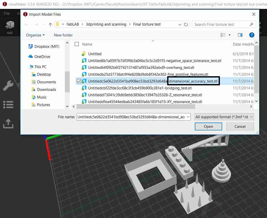
The stl file of the CAD model is imported in ideaMaker 3.3.0 software.
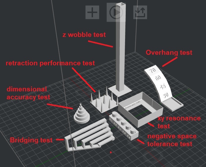
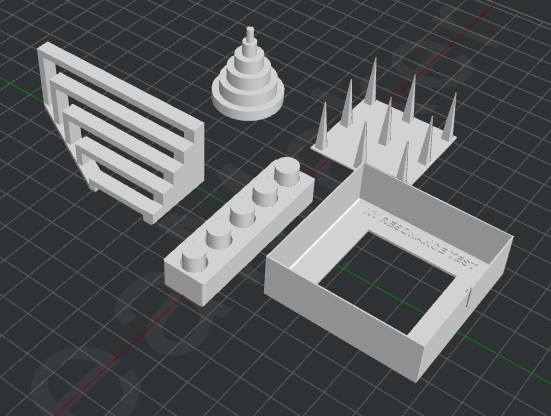
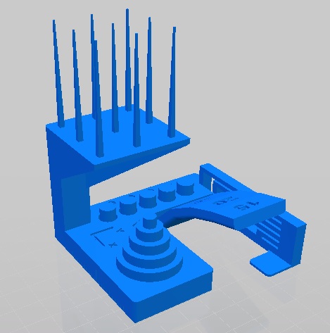
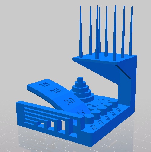
These are the different tests we wanted to conduct.
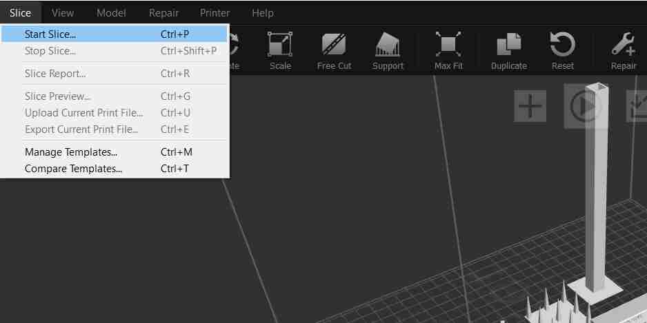
We start off by slicing.
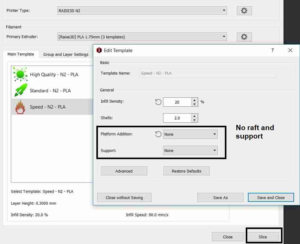
We don’t provide raft and support in the torture tests. I have also kept rest of the settings as default since the 3d printers are used in default mode.
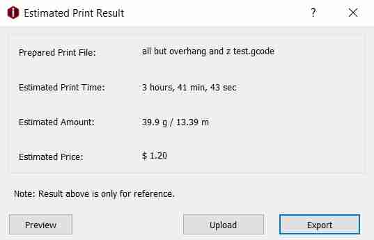
The total 3d printing time was about 4 hours. The exported file is a gcode which hasn’t been added as it is a 6 MB file.
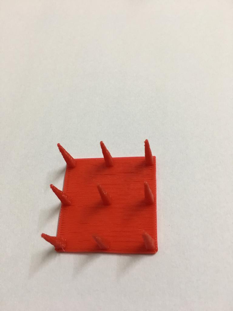
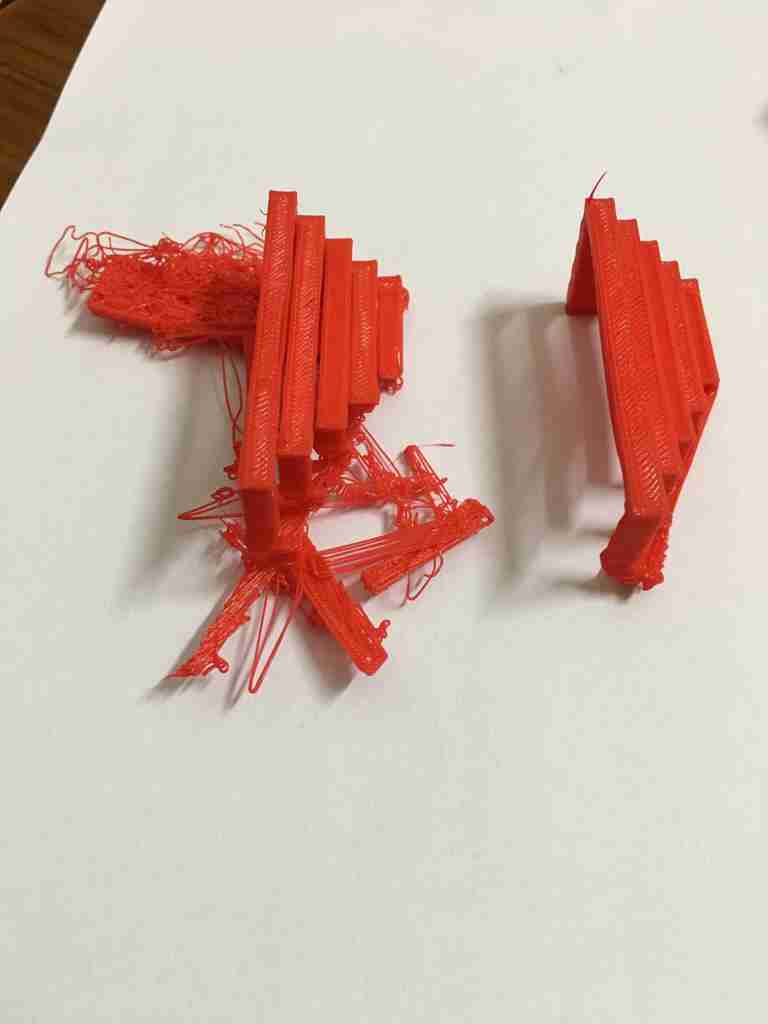
Retraction performance test
This test shows how good the printer is in jumping from one part to another.
The part came out quite well for this test.
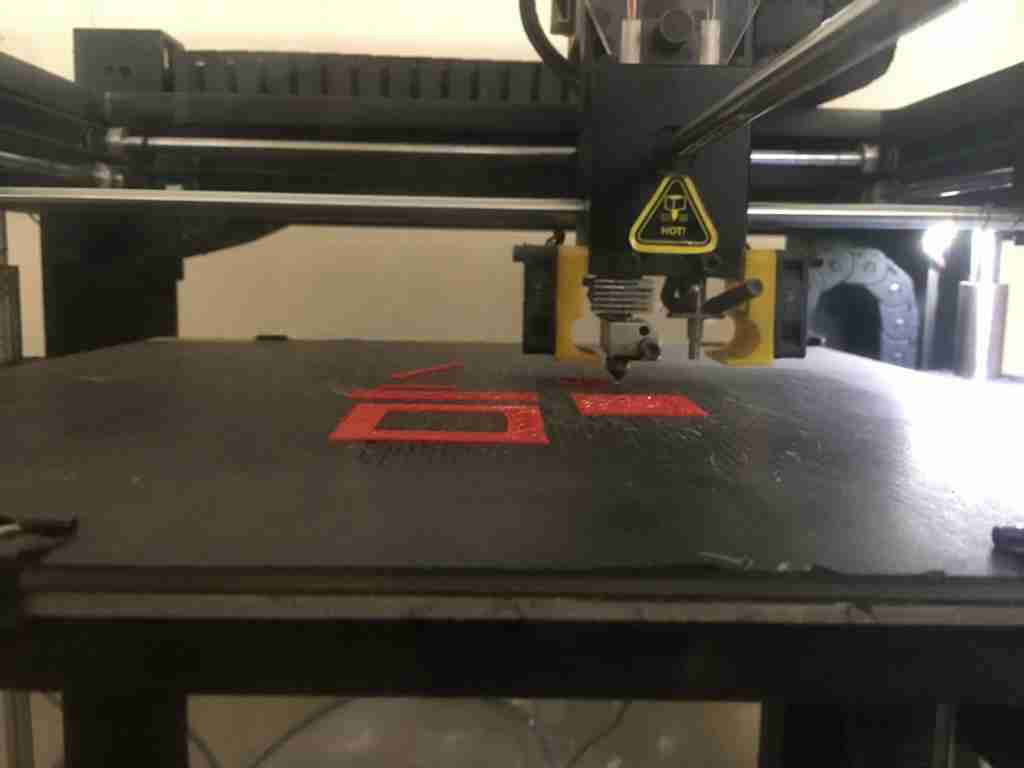
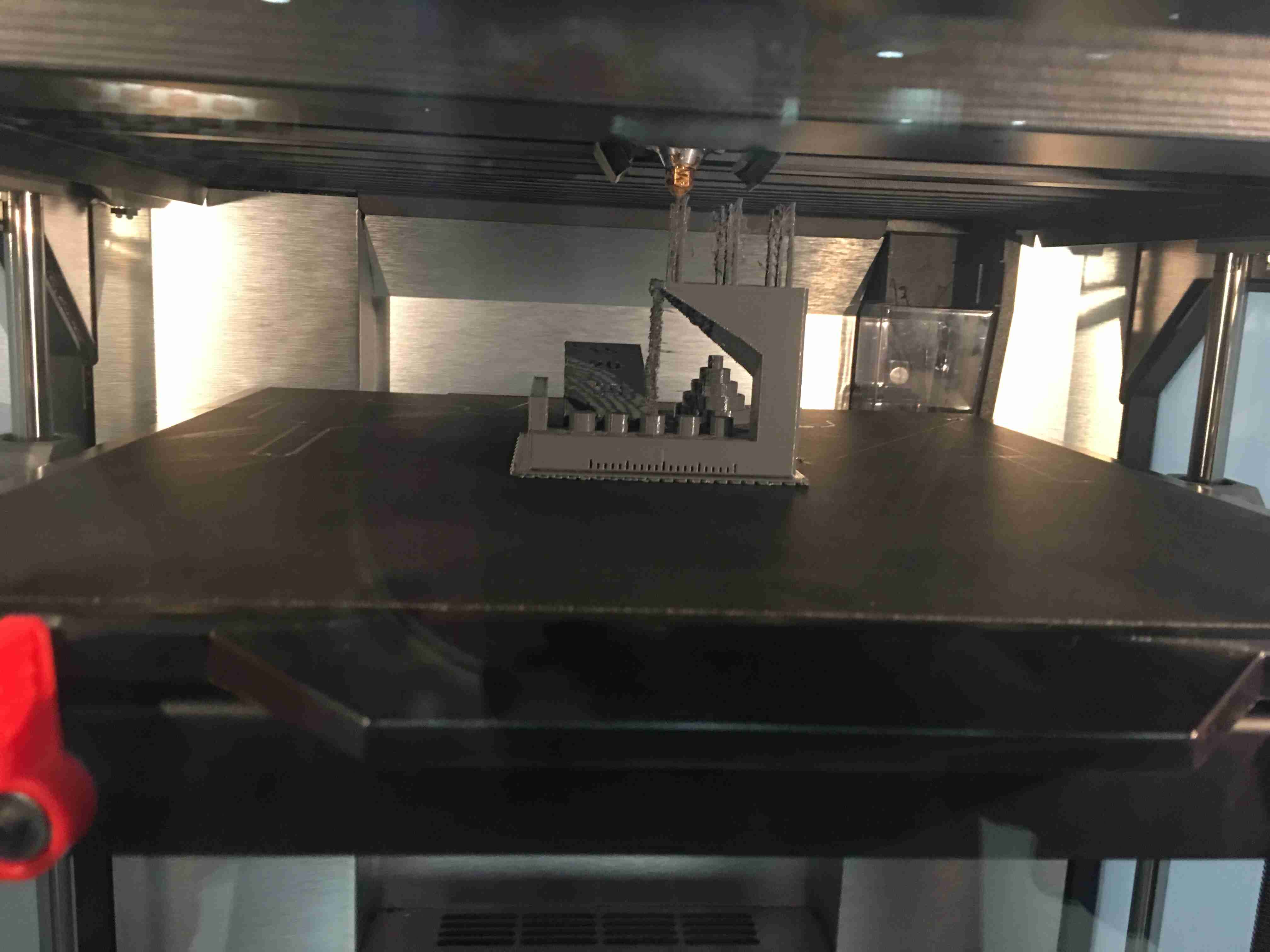
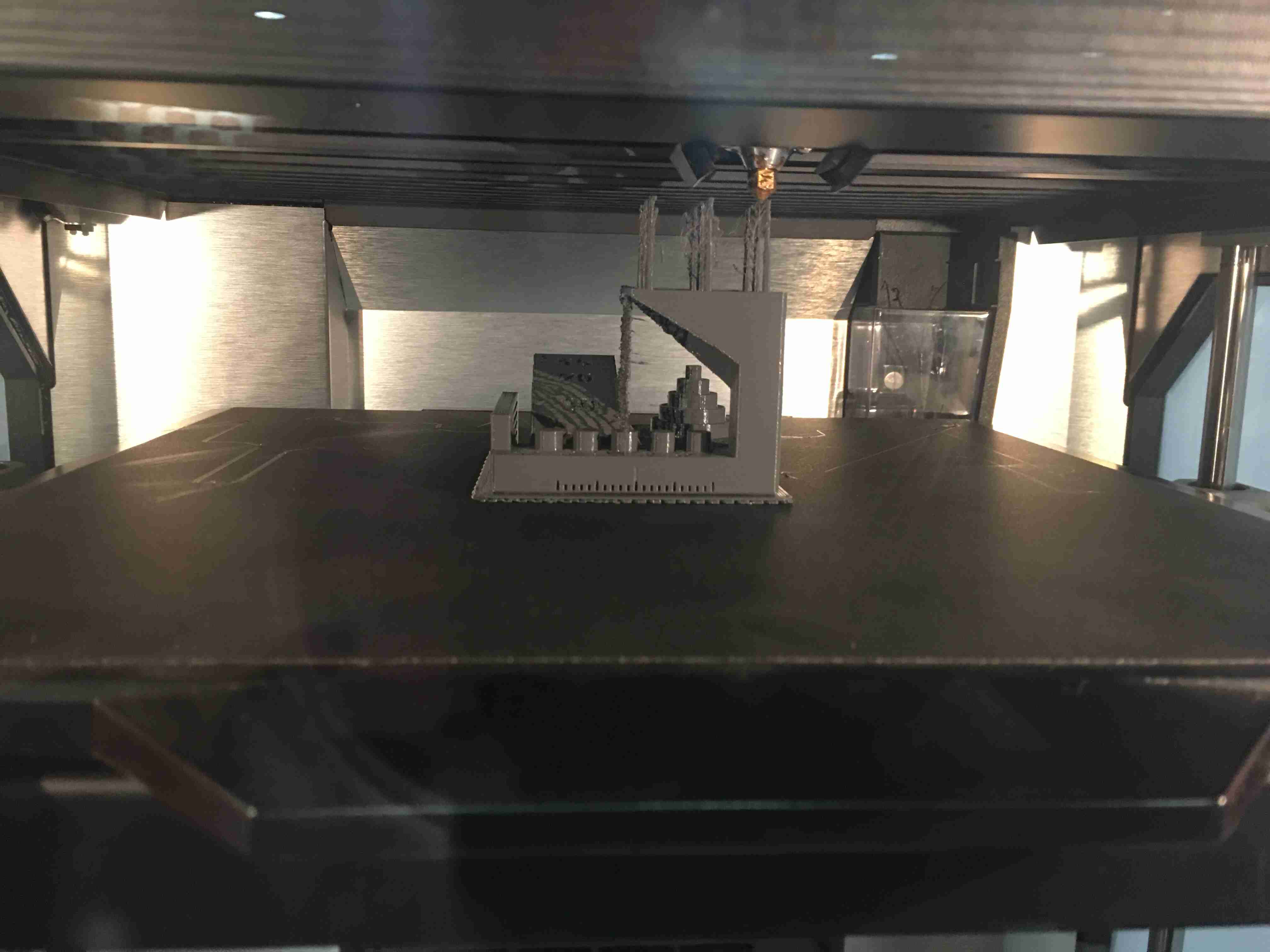
I took this test to the extreme and I gave five of the test parts together to check extreme retraction performance and also to save on time.
This shows the parts in the process of being 3d printed.
The dimensional accuracy test component, bridging test component and negative space tolerance test components didn’t come out right.
Here, we compare the component printed in the group vs it printed individually later.
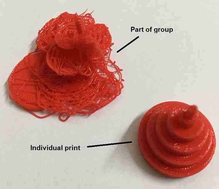
Because of no raft, probably the parts weren’t stable and got mixed up.
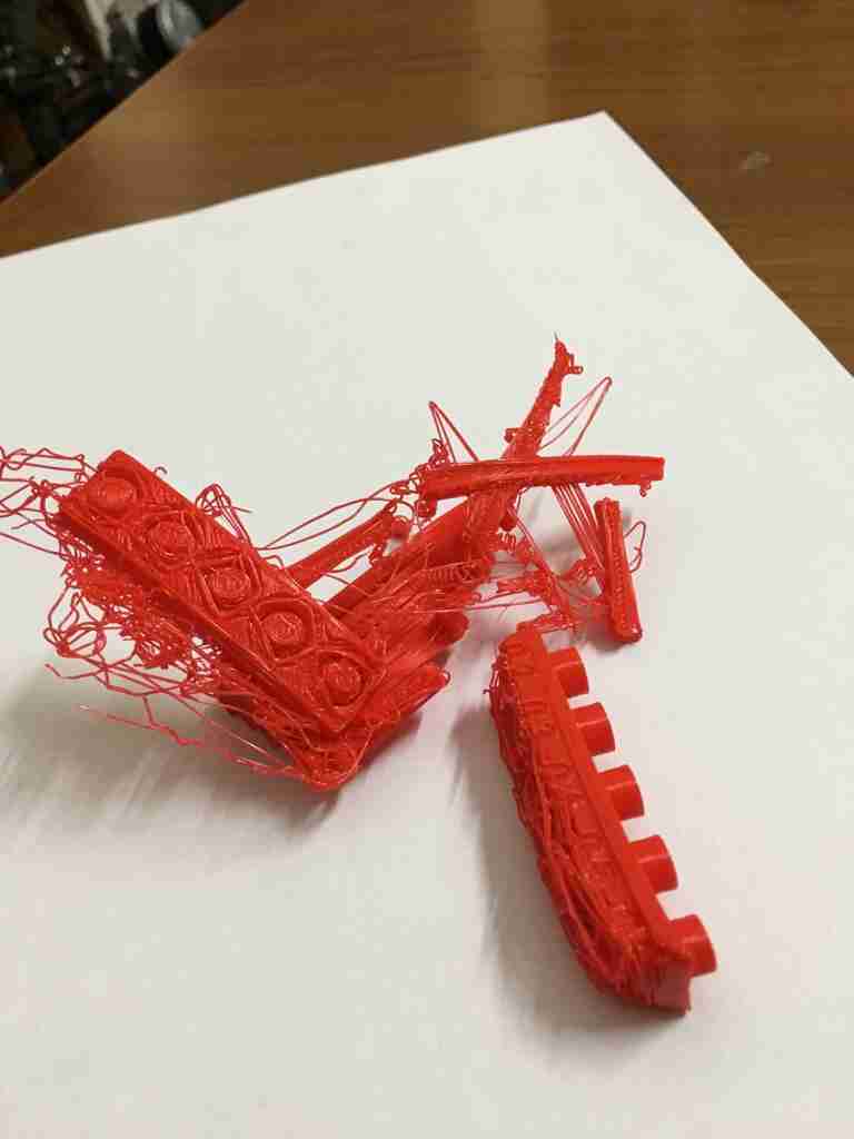
So, for the extreme retraction performance test, this printer is not of the best quality. It is better to print components individually rather than combining them.
Bridging test
In bridging test, the span gets wider and wider. We want to see if the material spans the gap without significant drooping. The CAD of the bridging test part shows no sagging.
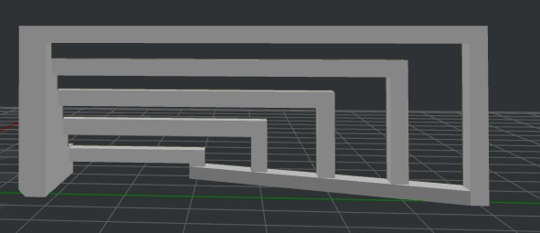
But the actual part droops even at the smallest span.
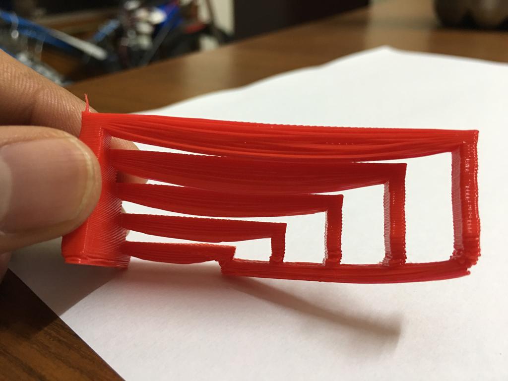
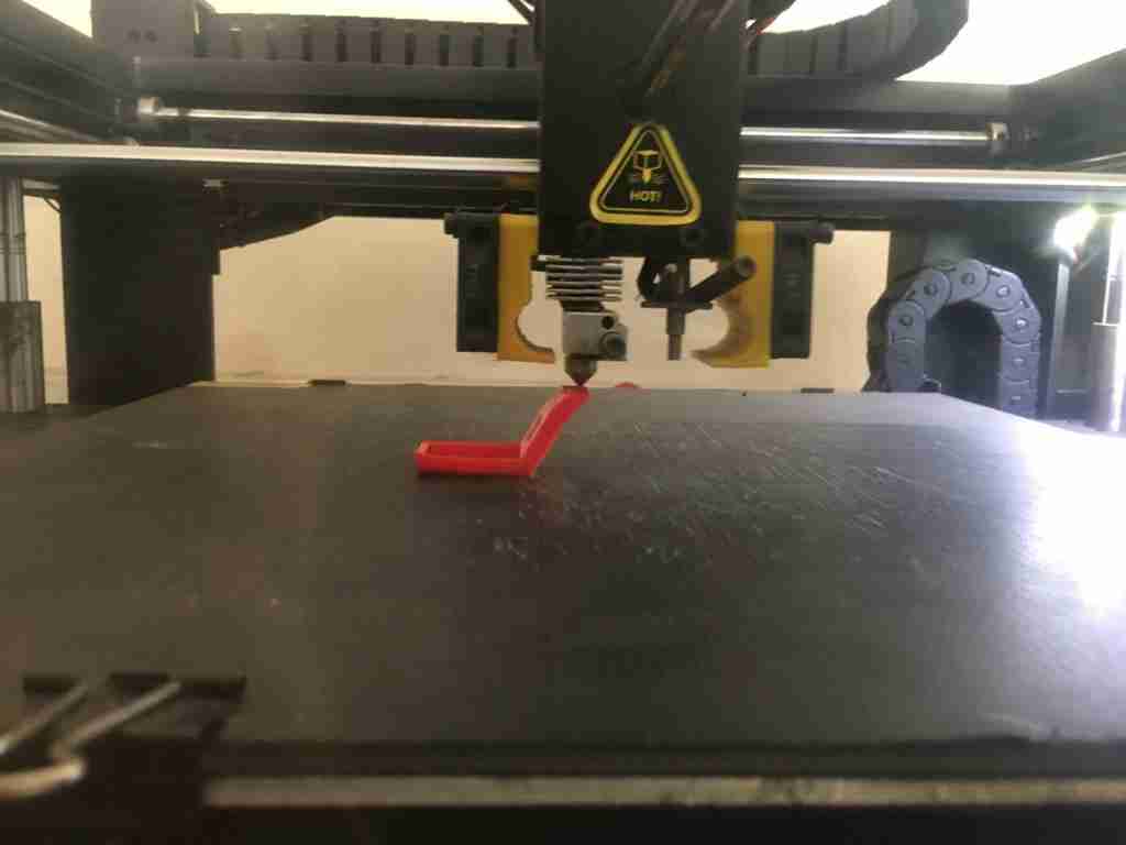
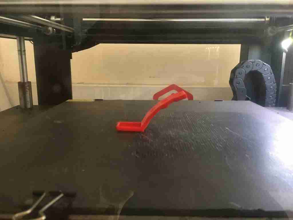
Overhang test
Here, we need to check how does the 3d printer print on the back of the overhang? After 45 degrees, it may get tricky.
This shows the test piece getting printed.
This shows the test piece finished printing.
This is how the overhang looks from the front.
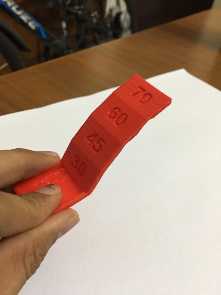
From the back, we do see that after 45 degrees angle, the quality of the part starts getting worse as the angle increases.
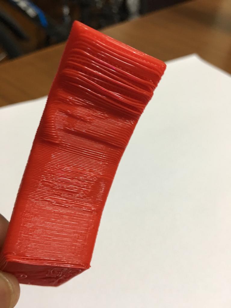
Z wobble test
This shows how straight and how tight the systems are for the rods and moving the z axis up and down. The test part turned out quite well which shows that the 3d printer has good performance in the z axis.
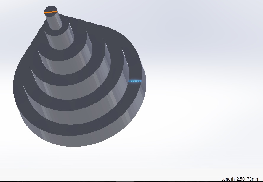
Dimensional accuracy test
We need to import the stl file for this test in Solidworks as a solidbody and use the measure tool to measure the dimension.
I used a digital caliper to measure the diameters of the actual printed part.
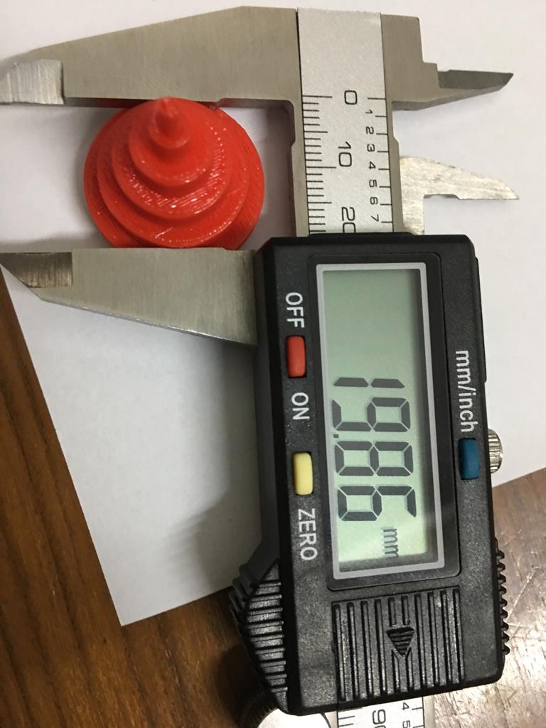
The table below compares the CAD model with the actual model as printed with this 3D printer.
| CAD diameter (mm) | measured diameter (mm) | difference (mm) | percent difference (%) |
|---|---|---|---|
| 2.50 | 2.37 | 0.13 | 5.2% |
| 5.00 | 4.70 | 0.30 | 6.0% |
| 10.00 | 9.85 | 0.15 | 1.5% |
| 15.00 | 14.90 | 0.10 | 0.67% |
| 20.00 | 19.82 | 0.18 | 0.90% |
| 25.00 | 24.80 | 0.20 | 0.80% |
We can see that the measured diameter is lesser than the CAD diameter. The dimensional accuracy increases as the dimensions increase.
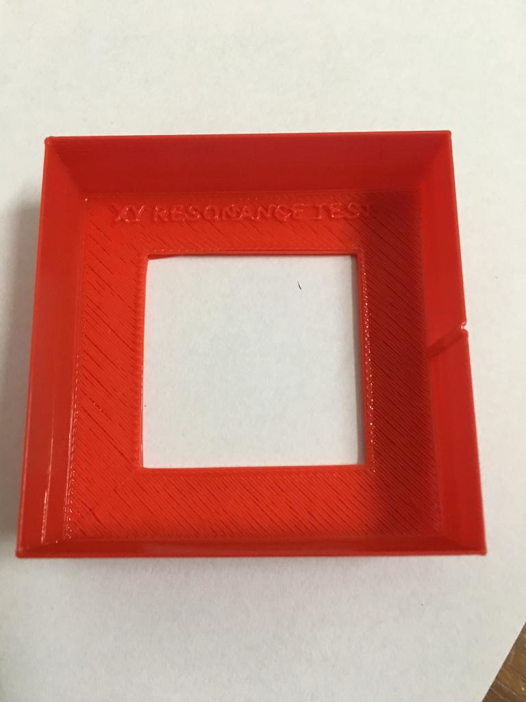
XY resonance
This is a binary test and we try to find if there are any ripples on the corners. The corners have come quite alright so this test passes.
Negative space tolerance test
Here, we have five pegs in five holes and each hole gets slightly larger. We need to pop the pegs out of the holes. The more pegs one can pop out, the better the printer is in printing the tolerances for parts.
Here, the part didn’t finish printing so this is the only test part which couldn’t be evaluated.
Conclusions from these tests
I would say that for the price of our printer, it seems to be decent for prototyping. It hasn’t been exceptional but it seems to perform alright for most of the tests.
We need to keep these aspects in mind while we design our part and know what to expect when we print. We need to be especially careful about the span, overhang angle and dimensional accuracy.
We also need to make sure that we print only one part at a time as the retraction performance is not superb.
Makerbot Replicator Z18
This was the printer at the AKGEC fablab. We went with the ultimate torture test.
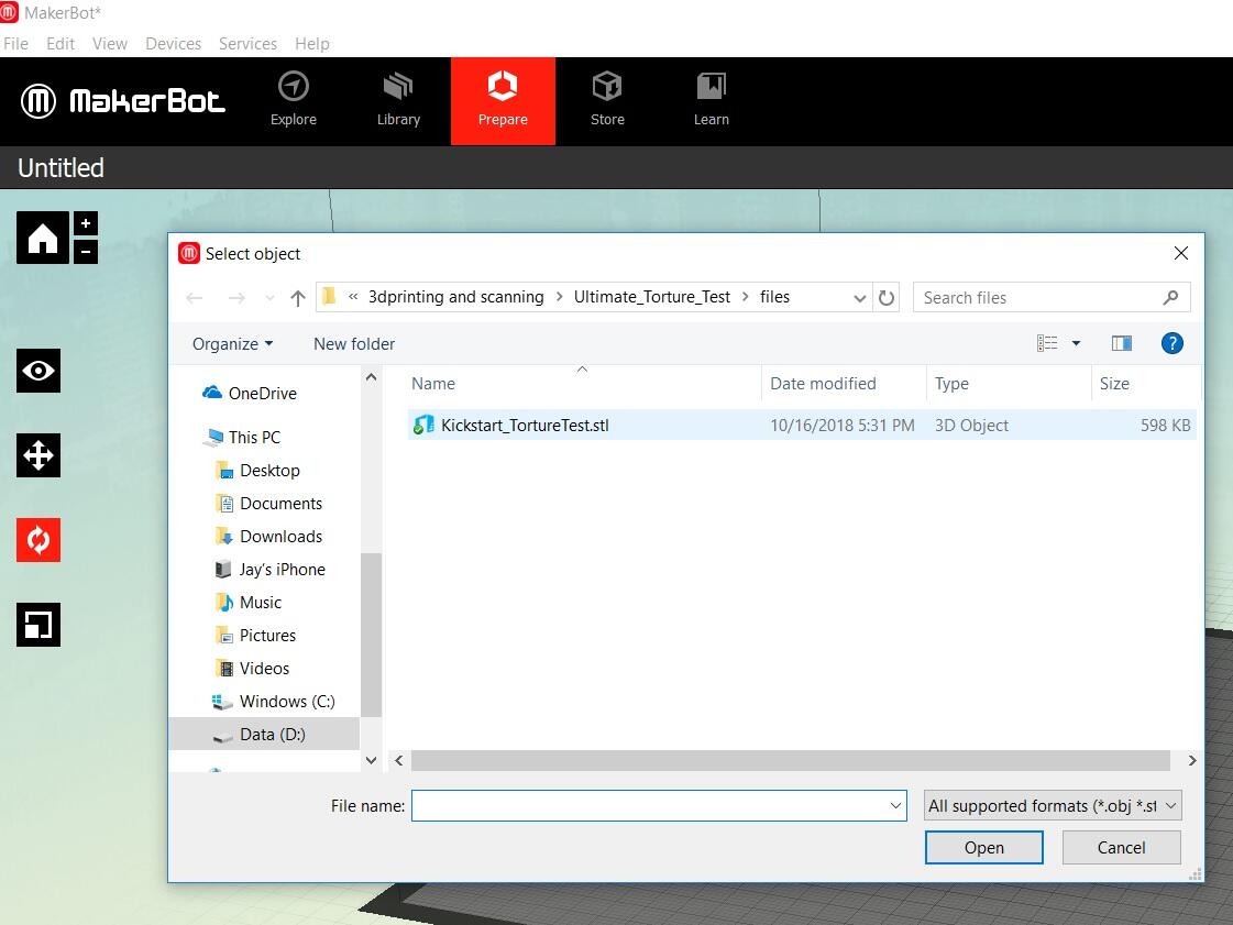
First, we wanted to understand how this printer worked. To prepare the .stl files to send to the printer, we downloaded the software for this printer. The software was fairly easy to follow.
First we opened the .stl file for the ultimate torture test.
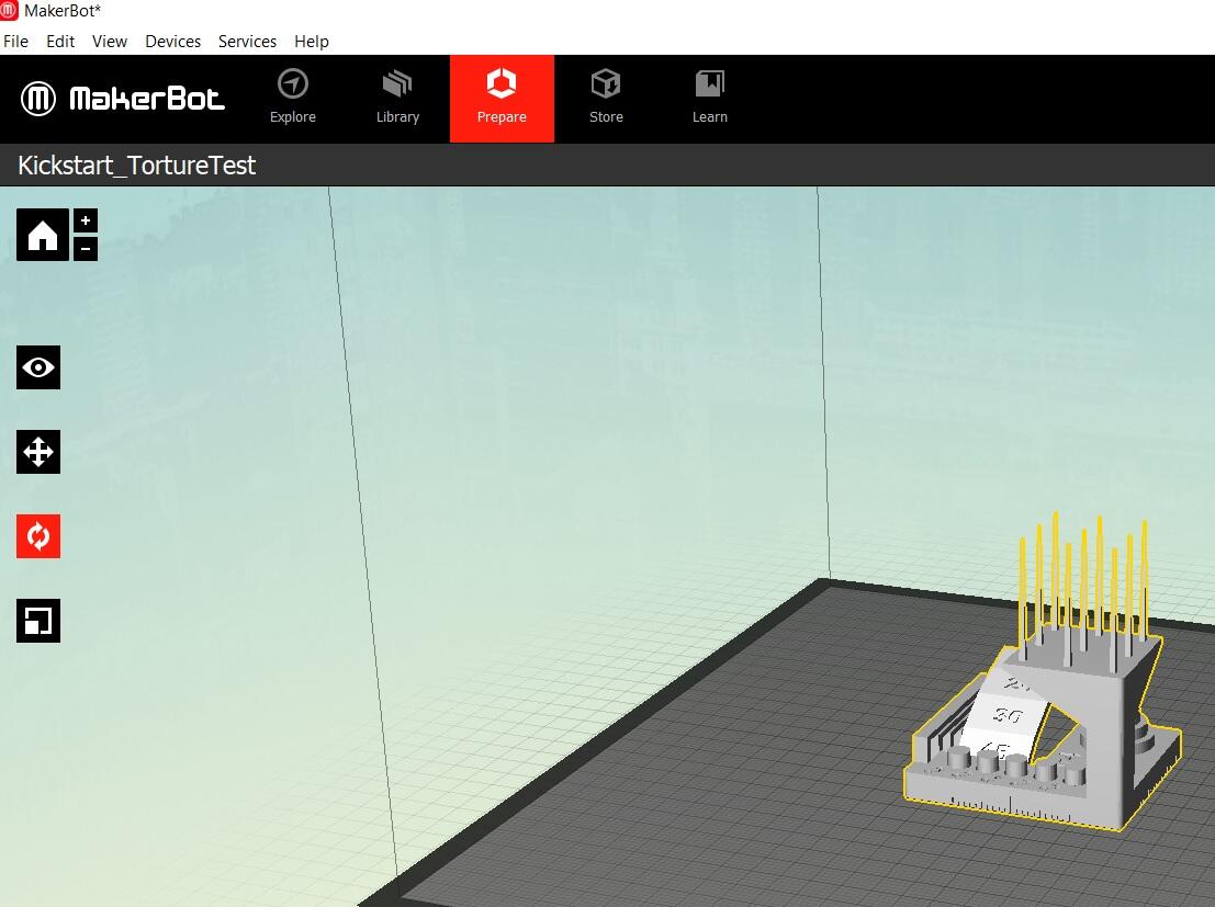
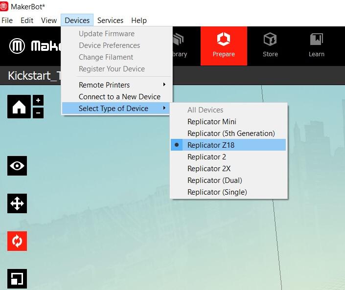
We had to select the right printer in the software.
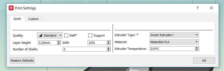
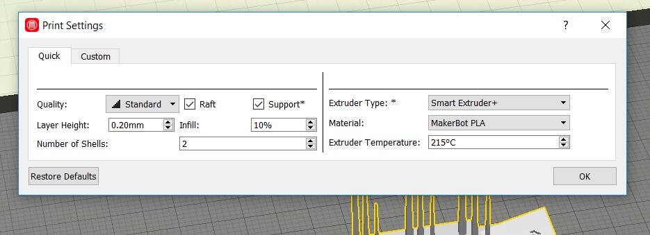
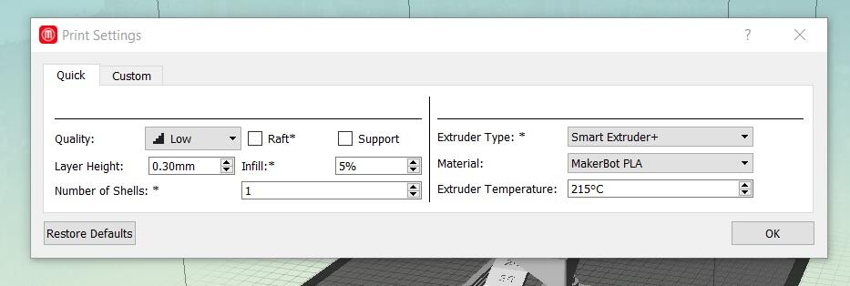
We could alter the print settings in this tab. We left the default settings for the test without the raft and support.
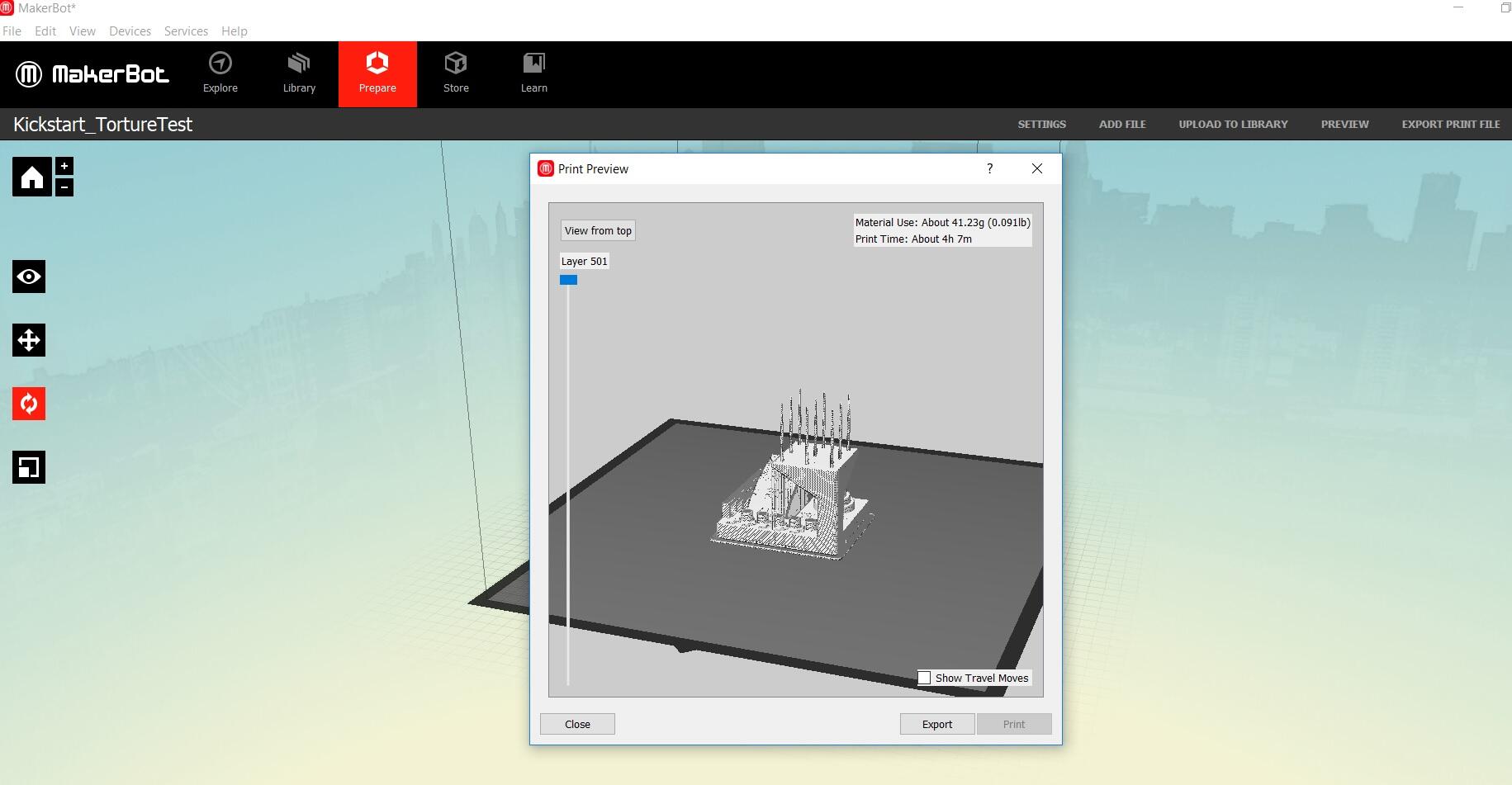
Once we were happy with the settings, we previewed the file and then exported it to .makerbot extension.
3d printer screens
Need to take these images from Rajat.
3d printed model without raft and support
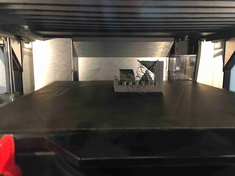
I was very excited to see the build progressing well.
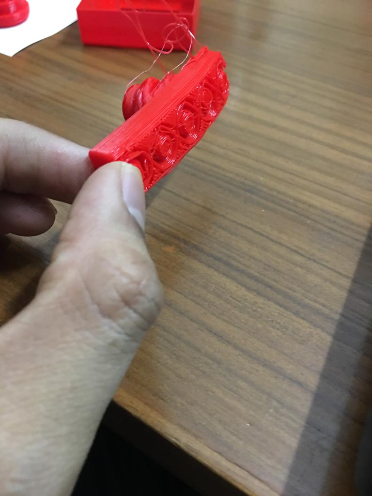
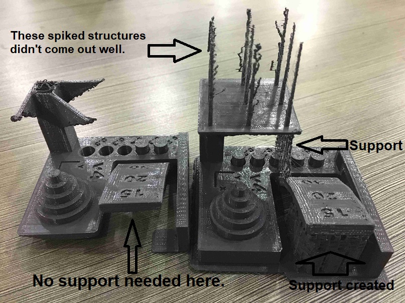
The print didn’t proceed as per expectations after a while since we didn’t have support and we had to cancel the print due to this spaghetti of PLA.
3d printed model with raft and support
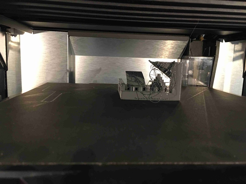
For the next test, we added raft and support as per the print settings. We also wanted to go for higher quality settings but that was doubling up the print time from 4 hours to 9.5 hours so we kept the standard settings only with raft and support.
The build finished without failing this time.
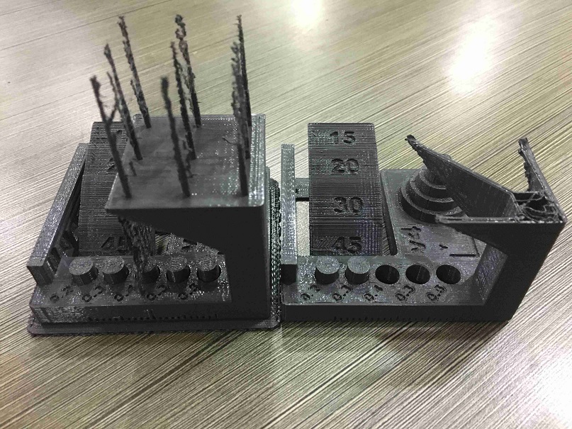
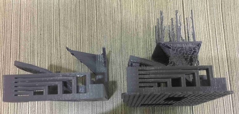
Comparison of the two models
These are the two views of the stl file for 3d printing of how the printed part should have looked.
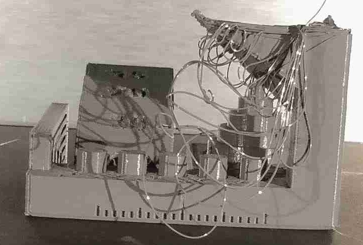
These are the different views of the failed part on the left and the completed part on the right.
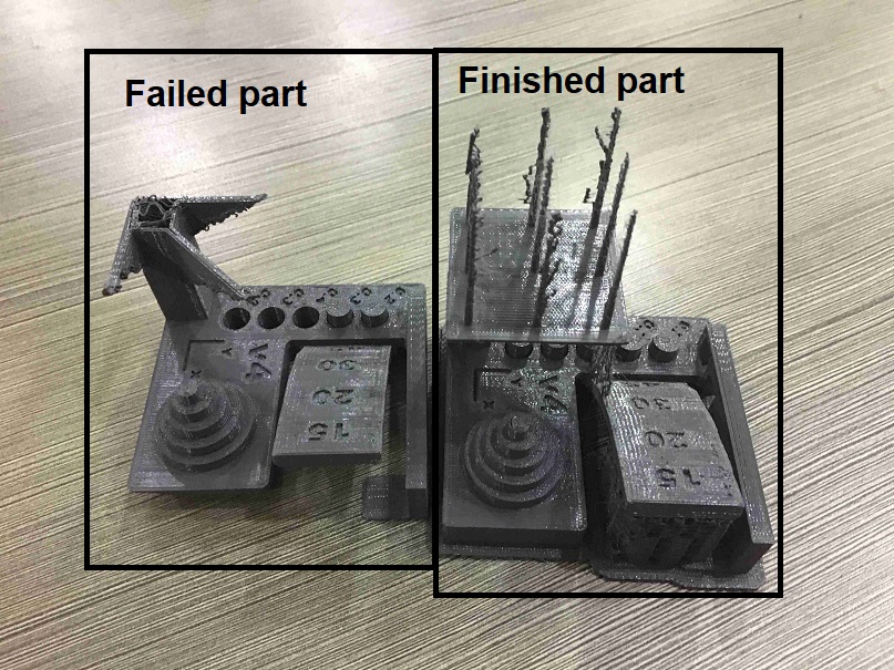
These are the different views of the failed part on the right and the completed part on the left.
We could have also explored changing the raft and the support one at a time to see the effects.
We could have also altered the settings to lower quality and compared the various parameters.
Individual 3d printer assignment
I have tried two objects for 3d printing. Both of these objects have undercuts so it wouldn’t be possible to make them with subtractive processes easily. Basic table with overhang is 3d printed with Makerbot and the cup with Adroitec 3d printer, which I used for tests.
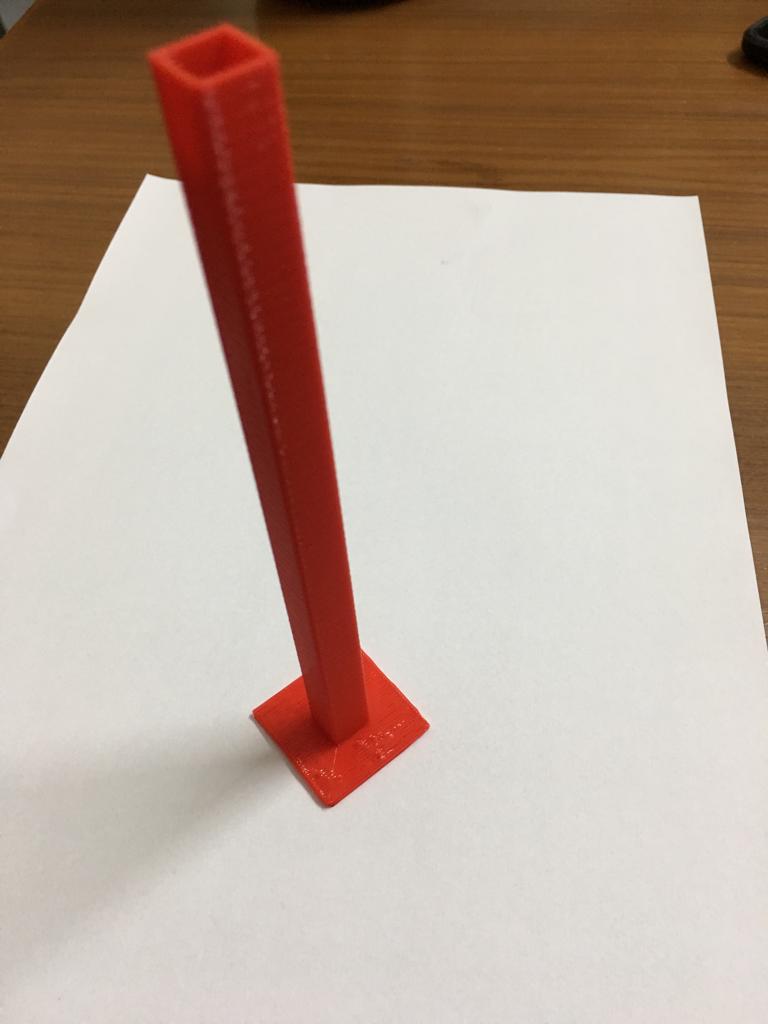
Basic table with overhang
I started with a basic table in the spirit of spiral development.
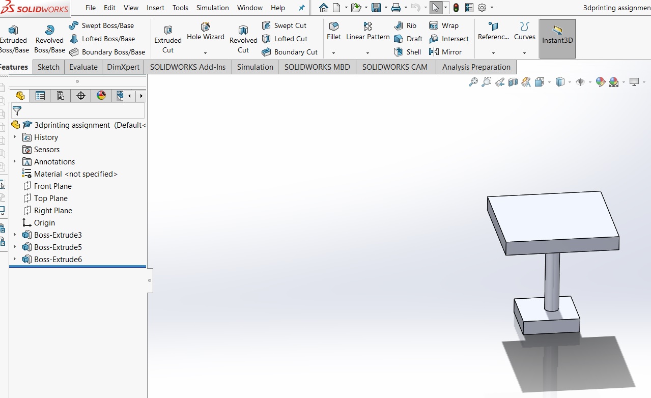
This object was 3d printed on Makerbot Replicator Z18, which was used for the group assignment. I realized that there was a lot of support used for the table. I am curious about the how could I change the parameters to reduce the amount of support used.
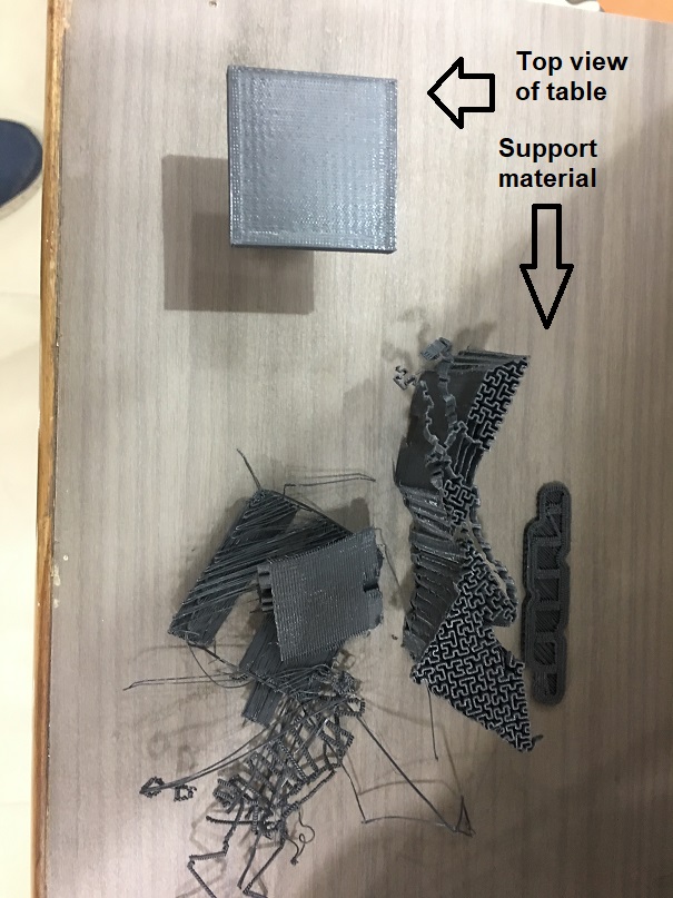
The table stand was very thin and broke while removing the support.
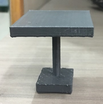
This simple piece lead to quite a lot of learning.
Cup
I wanted to make something simple and useful. This was a more advanced CAD for 3d printing. This was made in Solidworks and exported as an stl file.
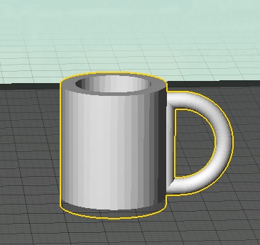
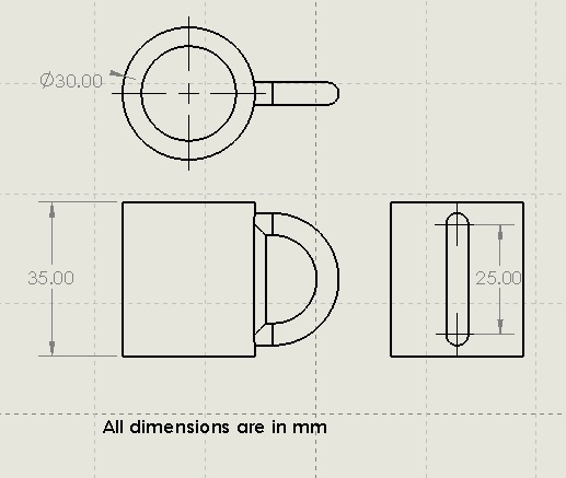
The cup was kept small to reduce the build time. The drawing shows the top, front and right hand side views.
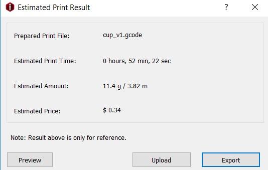
This object was 3d printed on my office 3d printer, Adroitec RxP2200, which I was able to get access at the place of my work i.e. IIT Delhi. I imported the stl file of the cup in ideamaker software.
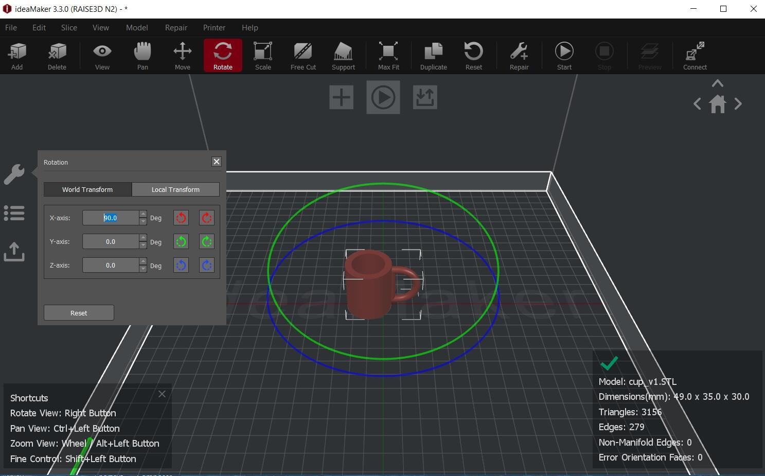
I selected the right printer type and the print quality parameters. Raft was selected with no support.
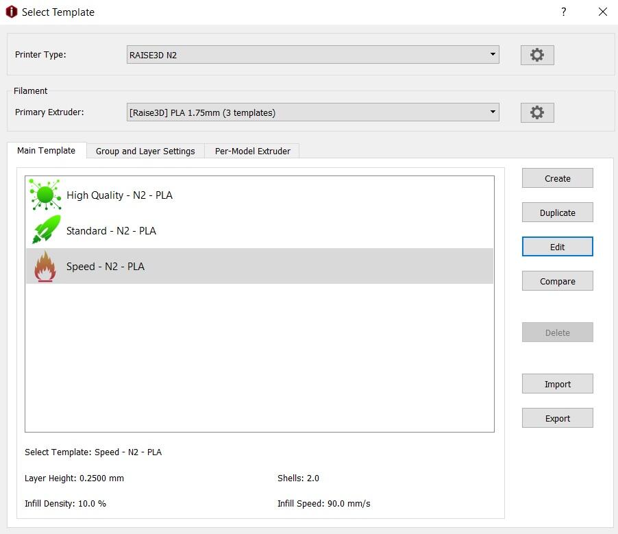
I sliced it to find the build time, which was 53 minutes. I then exported it into g-code which could be read by the printer.
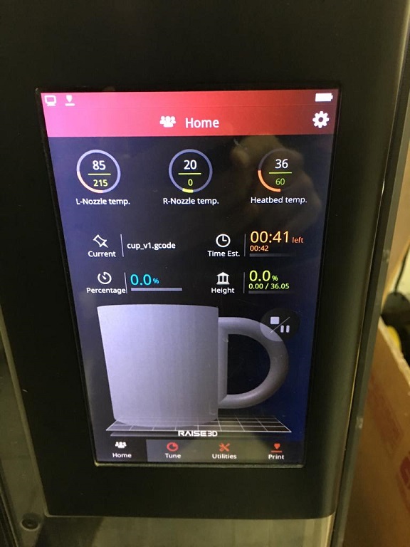
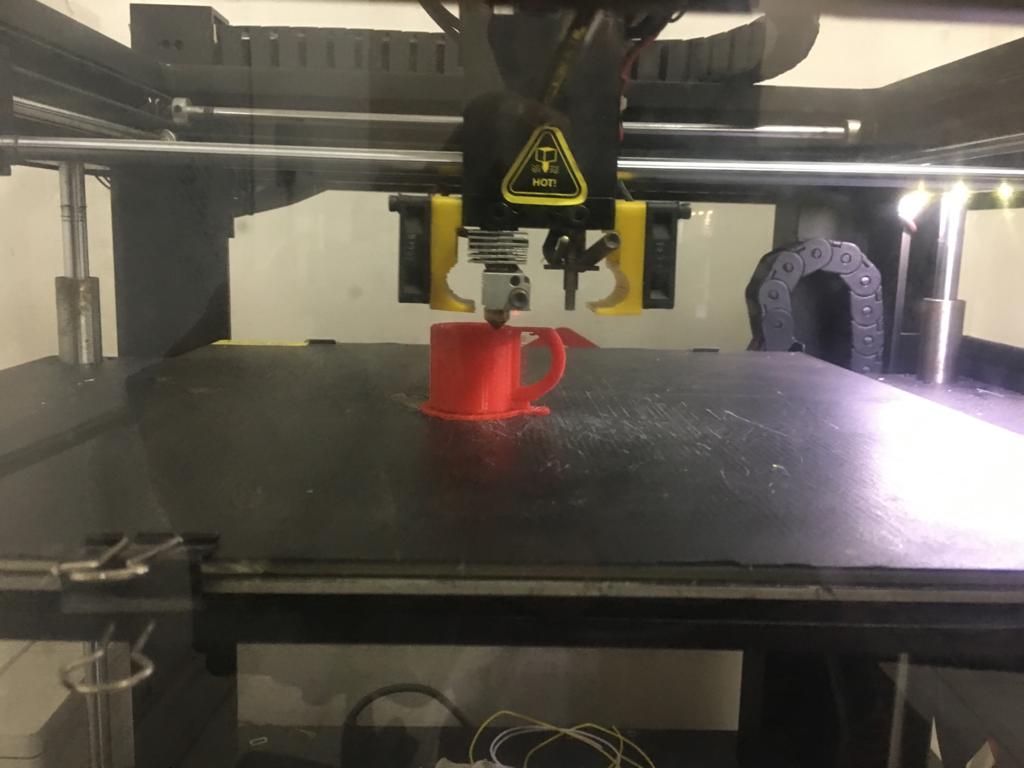
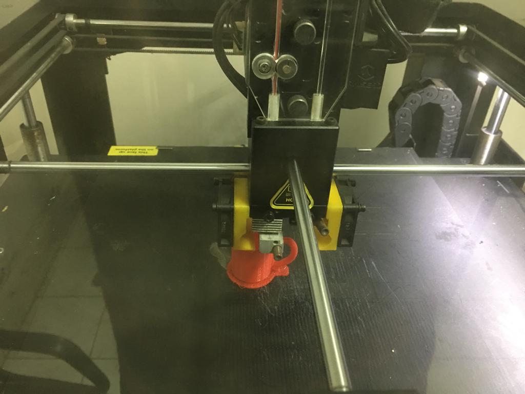
I inserted the usb stick into the 3d printer and pressed print to start the process.
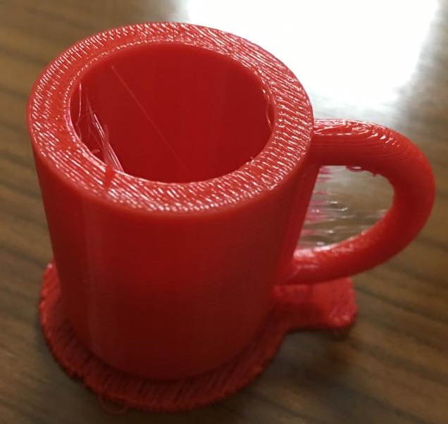
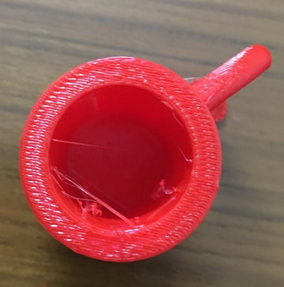
I cleaned up the model to remove the raft and the extra material to make the surface finish better.
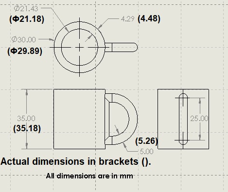
The table below compares the CAD model with the actual model as printed with this 3D printer.
| Dimension type | CAD dimension (mm) | Real dimension (mm) | (CAD - Real) Difference (mm) | Comment |
|---|---|---|---|---|
| Outer diameter | 30.00 | 29.89 | 0.11 | actual outer diameter is smaller. |
| Inner diameter | 21.43 | 21.18 | 0.25 | actual hole is smaller by ~ 1.2%. |
| Difference in diameter | 4.29 | 4.48 | -0.19 | |
| height | 35.00 | 35.18 | -0.18 | actual height is greater by ~0.5%. |
| handle thickness | 5.00 | 5.15 | -0.15 | actual handle thickness is larger by ~3.0%. |
From the observations, it can be concluded that the actual model has greater width and actual holes are smaller by a small percentage. The error may also be due to roughness in surface finish.
3D Scanning
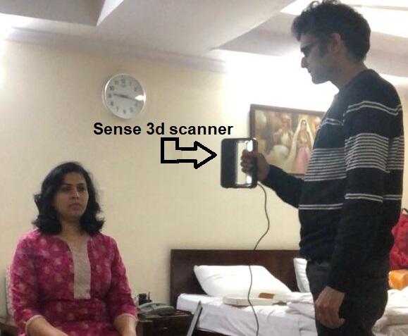
3D Scanner - Sense 1st generation
I borrowed this scanner from a faculty at IIT Delhi where I work. I downloaded the 3D scanner software from 3d systems website.
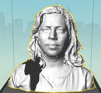
Scanning the head of a human
I started with the scanning of the head of my wife.
This is the Sense software interface first screen.
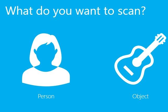
I wanted to scan only the head.

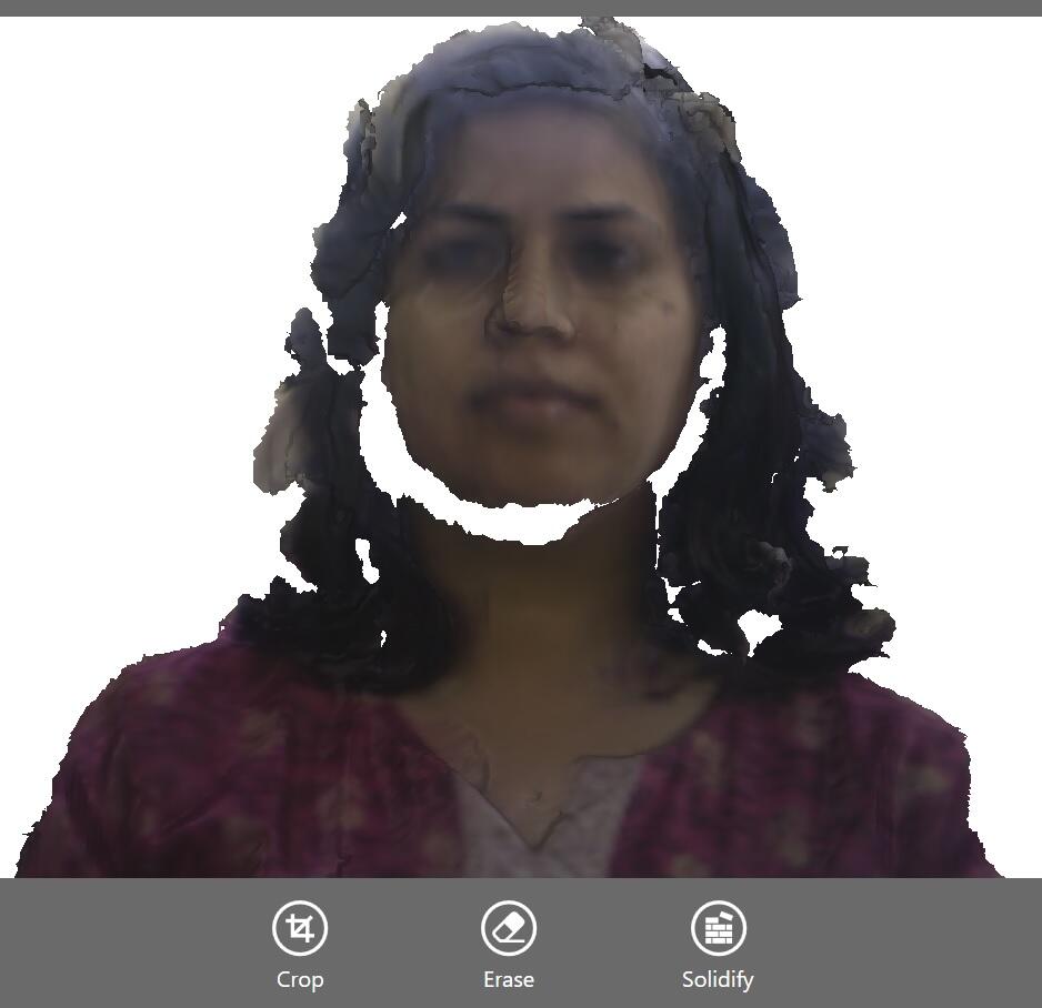
This is the first screen for scanning the human. The scanner was kept at the right distance to minimize the white areas.

The scanner lost tracking at times. This could happen if one moves across the human too fast. One should avoid to lose tracking. If the tracking is lost, one should come back to wherever it was lost.
![]()
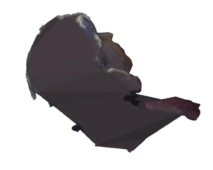
When the scan is complete from all sides, including the top, model can be created by working with the ‘solidify’, ‘crop’ and ‘erase’ options.
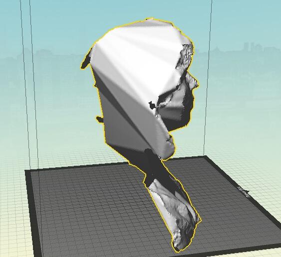
After model creation, the head misses out the features at places.

I had lost tracking on the back even after repeated tries, so I couldn’t get the back of the human head in this case.
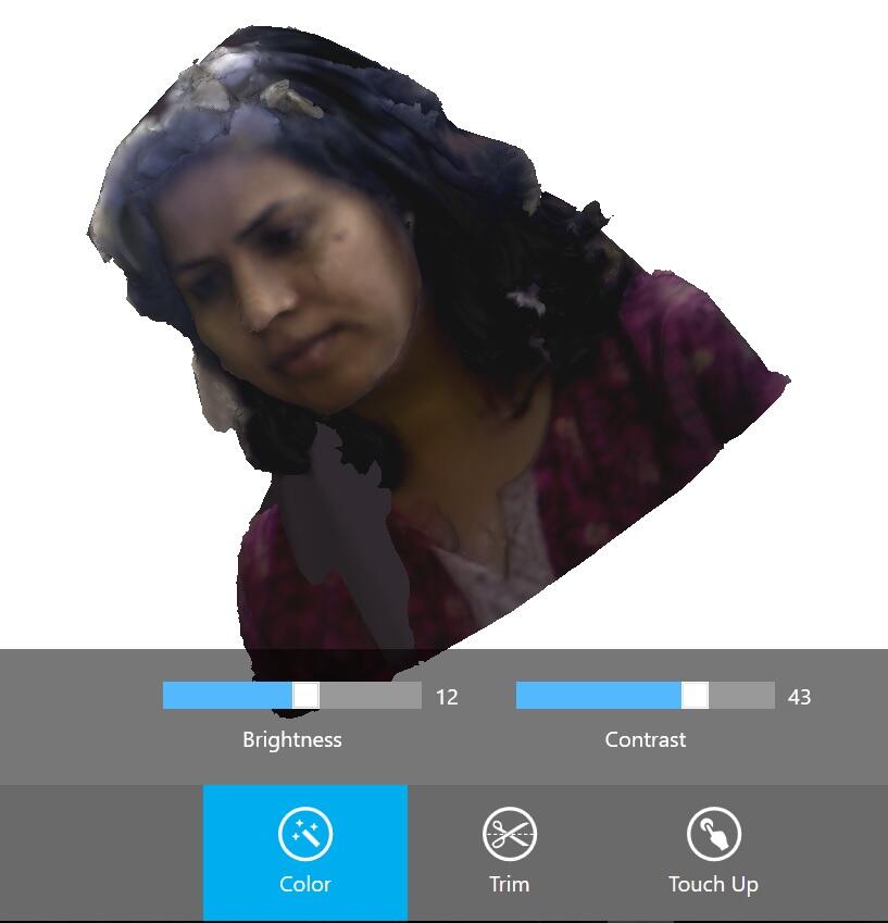
The color is used to adjust the brightness and contrast.
This model was saved as an stl file and was opened in makerbot desktop software to see the front and the back views.
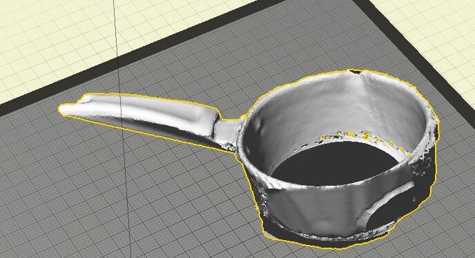
Scanning an object
A utensil was also scanned as the object.
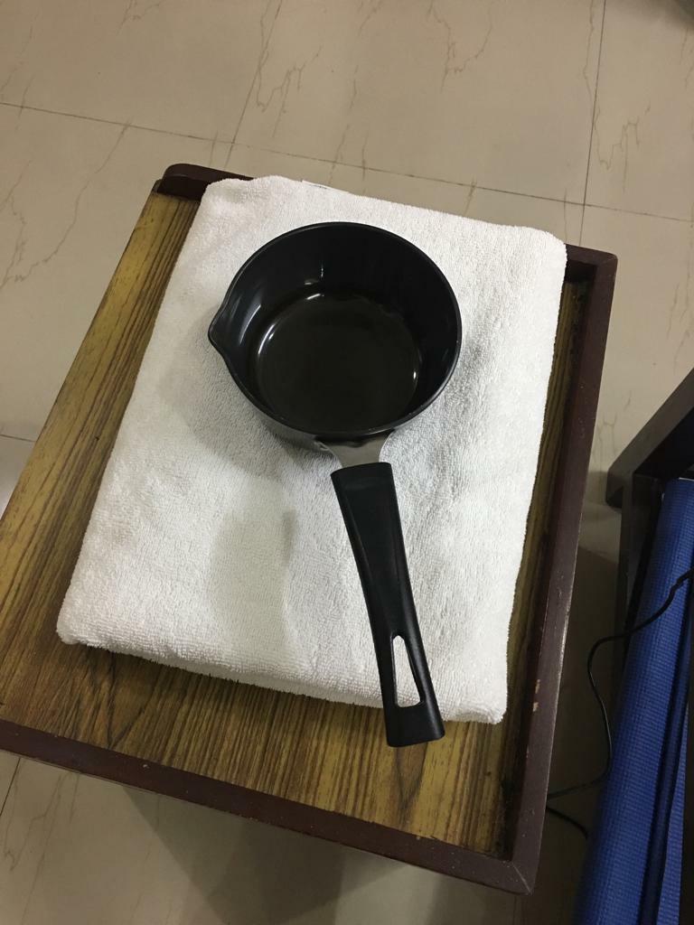
The utensil 3d scanning also followed the same procedure as the human head.
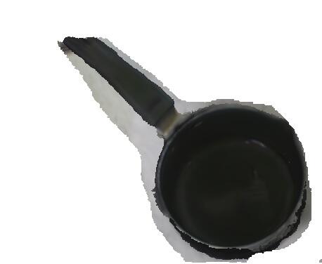
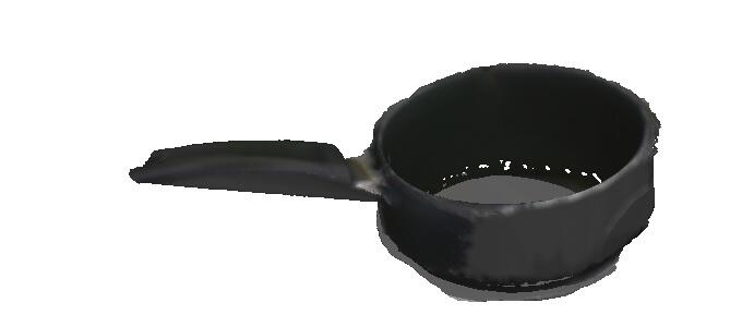
This was the final utensil stl.
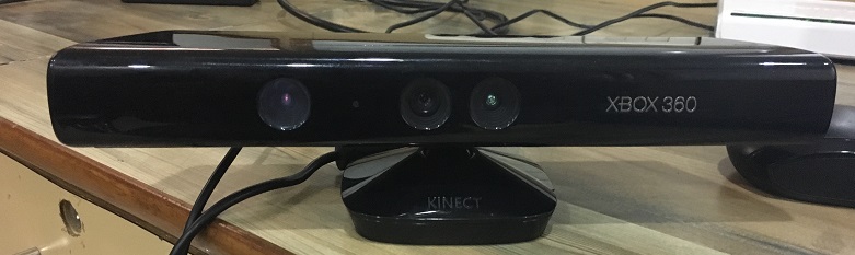
3D Scanner - Kinect sensor with XBox
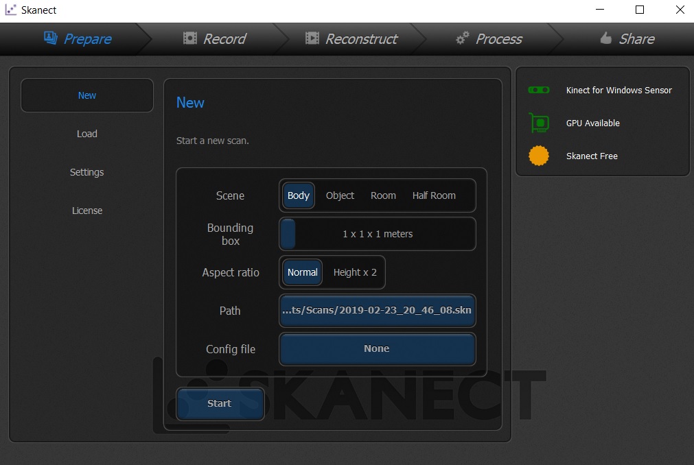
We had a Microsoft Kinect sensor for XBox 360 at AKGEC Fablab, which can be used for 3D scanning when used with Skanect software. I downloaded Skanect and the Kinect for Windows SDK 2.0 to use the Kinect sensor.
The Skanect GUI is fairly easy to use. I chose to scan a body which was myself sitting in the chair.
I rotated myself in the chair while keeping the Kinect sensor static. I moved slowly such that the sensor didn’t lose tracking. If it did, I came back to the point where it lost tracking and started again.

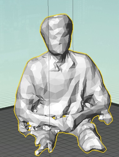
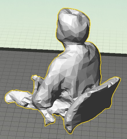
After recording, I made the model watertight and filled in the holes.
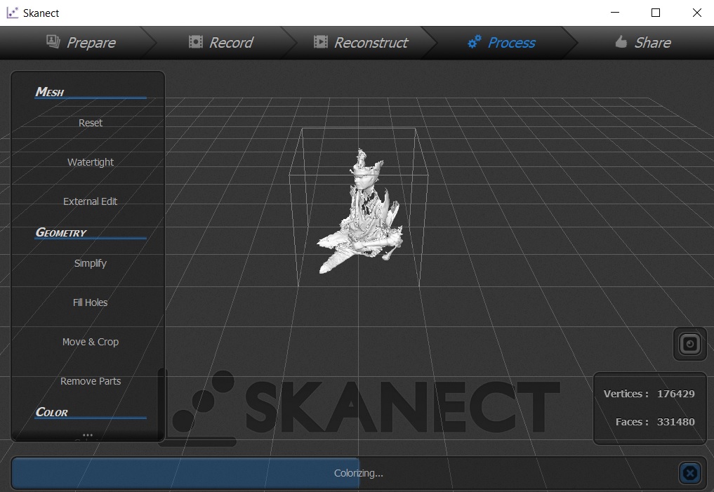
Then the model was saved as an stl file and viewed on the Makerbot Desktop software.
Learnings from 3D Scanning
Sense 3D Scanner
I was amazed at how this 3D scanner could scan a 3D object so quickly.
However, with the human head, I was losing tracking frequently on the back side even though I was slow so I was not able to get the entire human head. It also missed some parts in the front where the tracking was not lost. It was also not very convenient to hand hold the scanner for so long. A tripod use might have been helpful.
The lighting may also be playing a role. Diffused light is recommeded. This 3D Scanner may not work with transparent objects or objects without edges such as the cylindrical ones.
Kinect 3D Scanner
I used this sensor briefly. It did scan the object fully and is much cheaper than the Sense 3D Scanner. But the resolution of the Kinect sensor was not as good as the Sense 3D Scanner. However, when I used it to scan an object, it was capturing the objects around the object which I was interested in.
General learnings
3D Scanning is an exciting technology to know about. But for the 3D scanners that we explored, there is scope for a lot of improvement in terms of accuracy and user friendliness. I would like to see the more expensive scanners used for reverse engineering applications to find out their performance.
Design files
Download for the solidworks file for the CAD of basic table.
Download for the stl file for the CAD of basic table.
Download for the solidworks file for the CAD of a cup.
Download for the stl file for the CAD of a cup.

Solar powered electric bike con kit by Jay Dhariwal is licensed under a Creative Commons Attribution 4.0 International License