10. Molding and casting (Mar 27)
This week we were suggested to review the safety datasheets for each of our molding and casting materials and make and compare test casts with each of them for the group assignment. For the individual assignment, we had to design a mold around the stock and tooling that we would use, mill it (rough cut + three axis finish cut) and use it to cast parts.
Group assignment
Safety datasheets
Silicone rubber
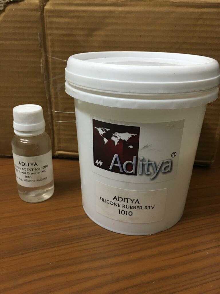
We were suggested to use Aditya silicone rubber RTV 1010 with the curing agent for flexible molds by our remote instructor Puneeth. I couldn’t find its safety datasheet. I found this information on their website. I am sharing the safety datasheet of another silicone rubber which should be close. This silicone has low viscosity and easy demoulding properties.
Another source of information is the customer reviews and Q&A on amazon website where I bought it from.
This is relatively cheaper and locally available in India. We need to mix about 30-40 gm of curing agent in 1000 gm of silicone. The curing time is 24 hours at room temperature.
Epoxy resin
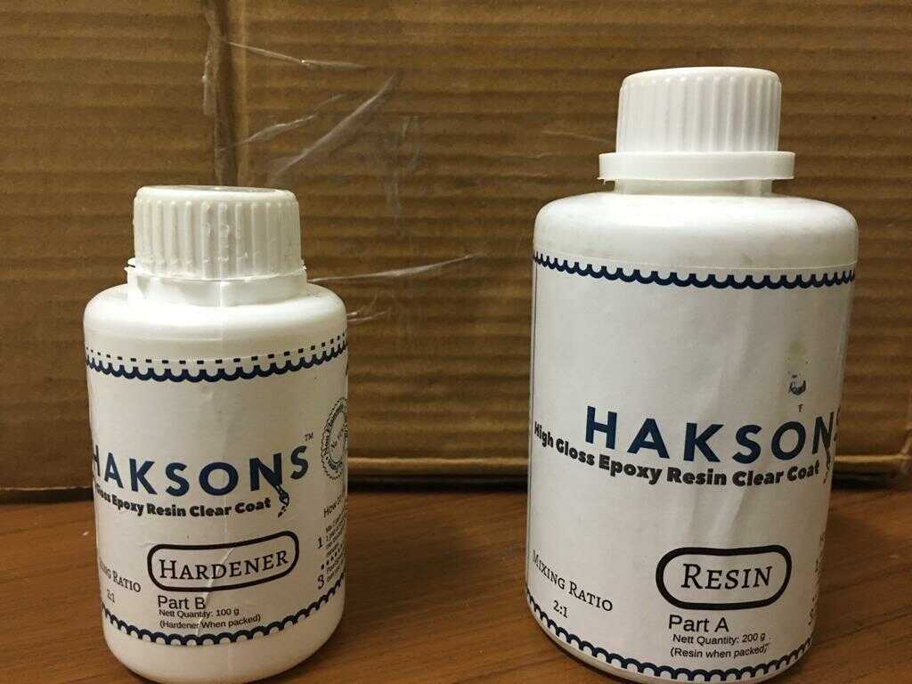
We were suggested to use Haksons resin and hardner for casting by our remote instructor Puneeth. I couldn’t find its safety datasheet. I found this information on their website. I am sharing the safety datasheet of another epoxy resin which should be close. This epoxy also has low viscosity and easy demoulding properties.
Another source of information is the customer reviews and Q&A on amazon website where I bought it from.
The resin and hardener was mixed in the ratio 2:1 as per the instructions given on the bottle. The curing time was 24 hours.
Test mold and cast
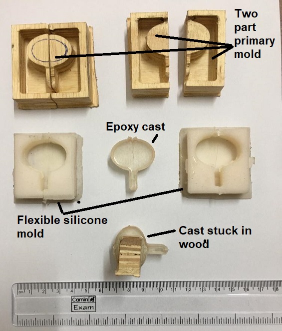
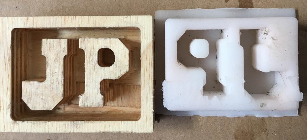
I was excited about this assignment. I wanted to cast a cup in two axes initially but that was getting very difficult and so I abandoned that idea. But I used those wood molds as my test pieces to experiment with the test silicone flexible molds and casts. The below image shows the three steps.
I created two part wood primary mold (two of these) with CNC router. I then created flexible silicone mold (two of them) by pouring silicone into the wood mold. I created epoxy cast by pouring resin+hardner mixture in the silicone mold.
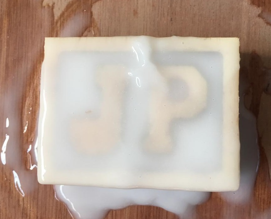
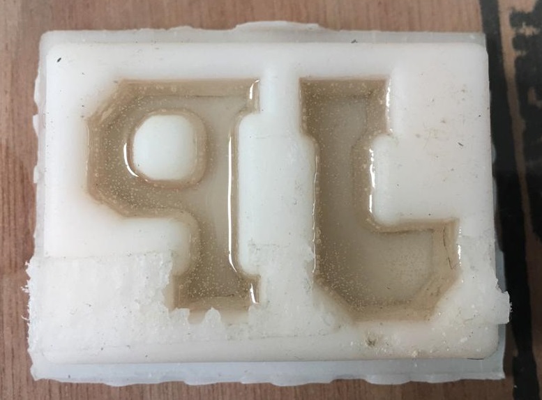
I also show that if I bypass the silicone mold step then the epoxy cast gets stuck in wood.
This was very good learning to create something useful.
Part to be casted
For molding and casting, I wanted to start with the CAD of the part that I wanted to cast, followed by making a CAD for the flexible silicone mold around it and then using this silicone mold CAD, I wanted to make the CAD of a hard plywood mold for the flexible mold.
I thought of casting the initial of my and my wife’s names i.e. J and P. To create a CAD of the initials in Solidworks, I thought of choosing from one of the attractive letter images from google.


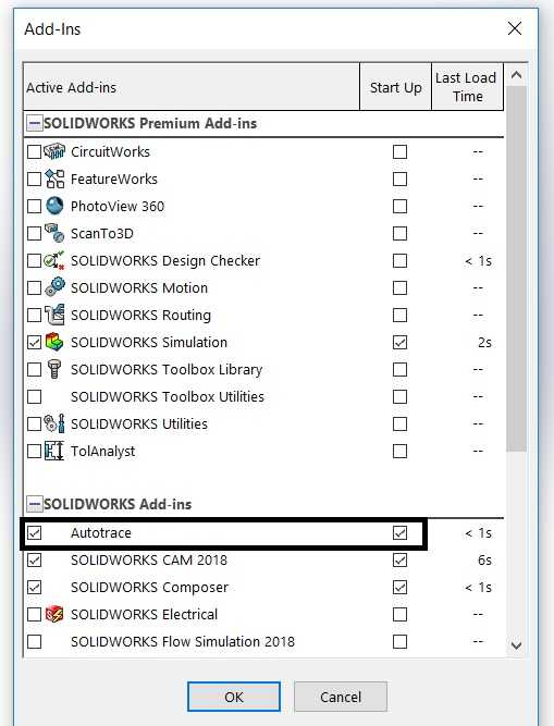
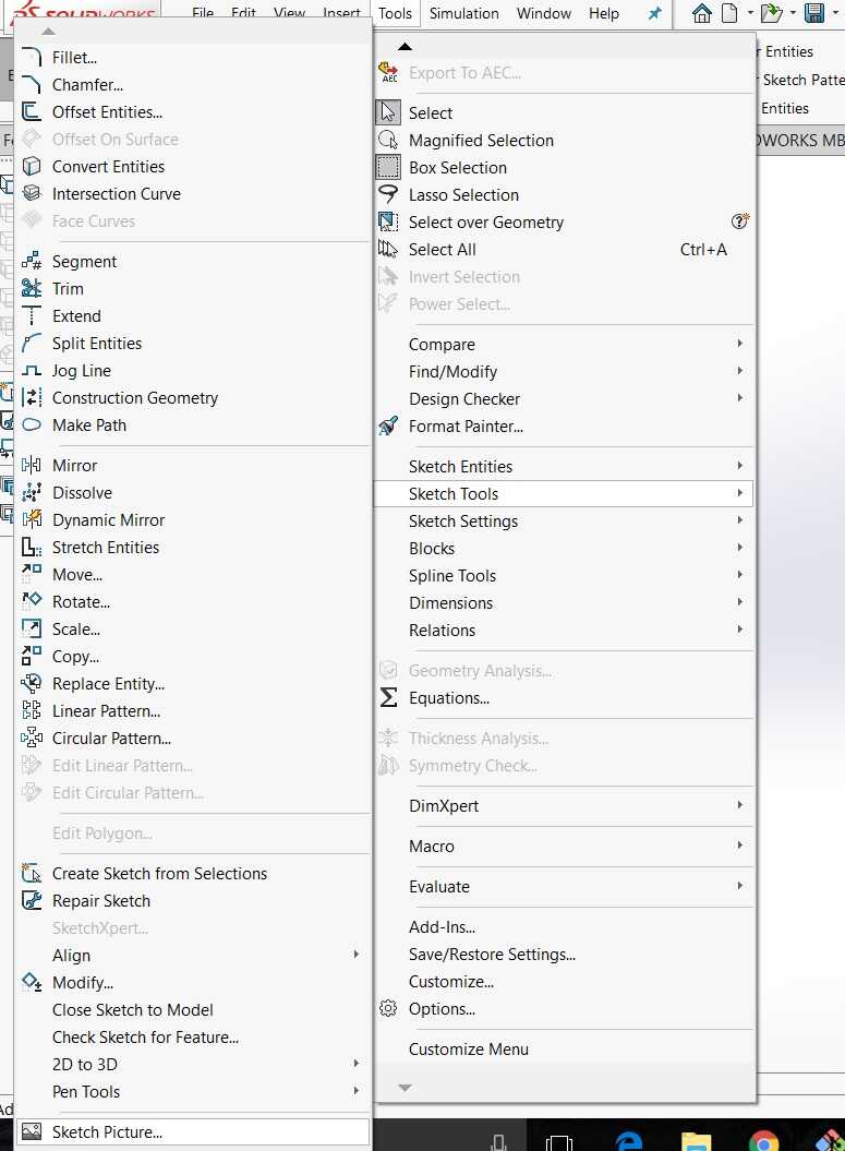
I looked for a way in Solidworks to trace these images and then trim them for better symmetry. I found an add-in called Autotrace. This can be found under Tools>Add-ins.
Next we start a sketch in xy plane and get into edit sketch mode. We click on Tools>Sketch Tools>Sketch Picture.
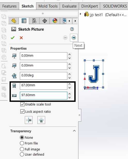
We select the image J and select its dimensions. After this, we select Next to Autotrace.
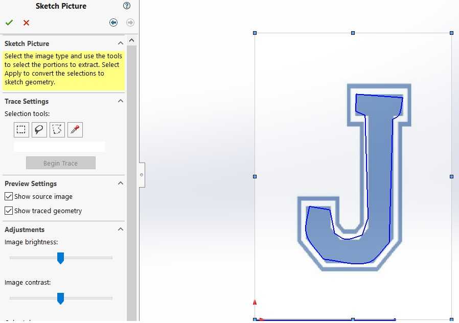
We select the use to select color in Trace Settings and Begin Trace. The trace that we get is not perfect but we can work with this to get the CAD that we want.
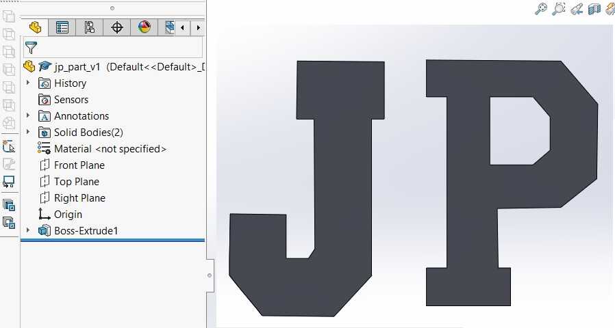
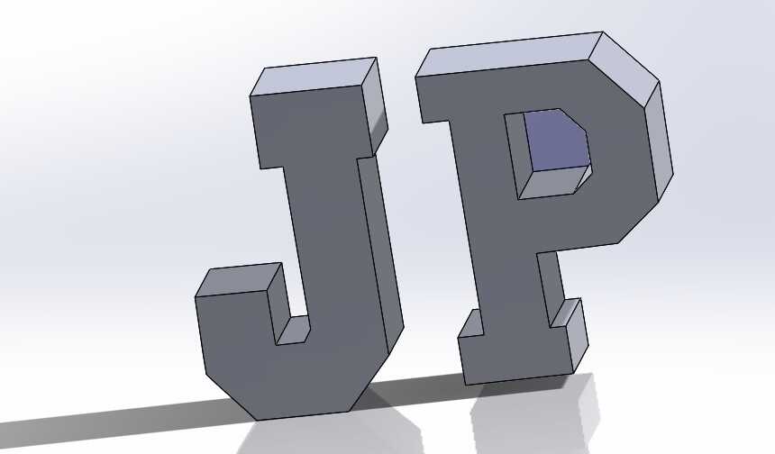
We delete the image now and repeat this process for the letter P image. The final CAD looks like the image below. The design can be downloaded.
Silicone mold CAD
The next step was to create a bounding box around the CAD to be casted to create a negative in silicone. 10 mm margin was kept on each side of our casted CAD.
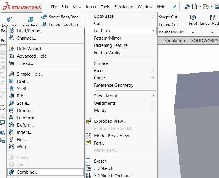
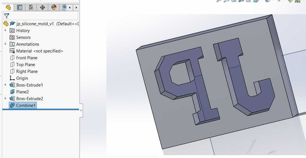
The casted CAD was subtracted from the bounding box to get the negative using the Combine feature.
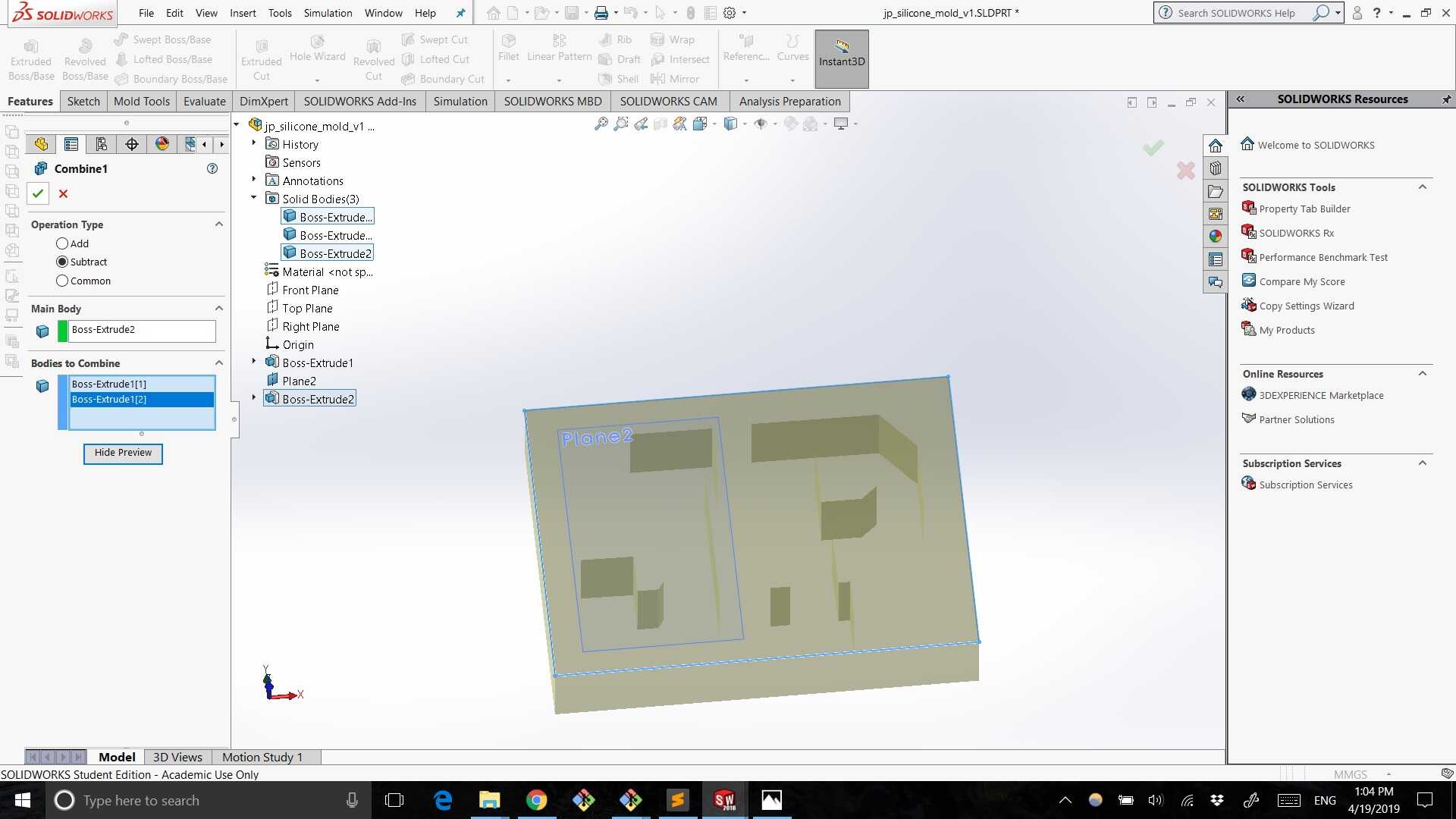
This is how the silicone mold CAD looked like.
Plywood mold CAD
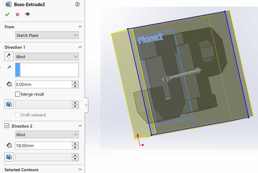
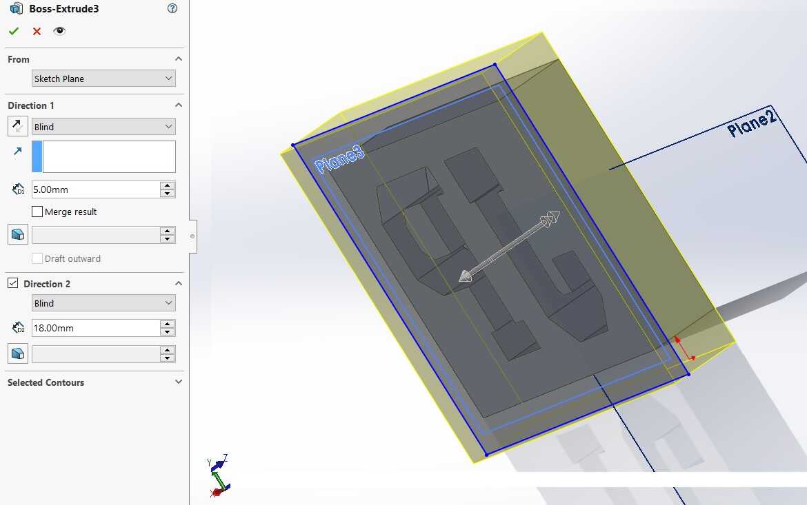
Same process as above was followed to create an plywood mold from silicone mold. A bounding box was created around the silicone mold. This box was extruded as per the image below.
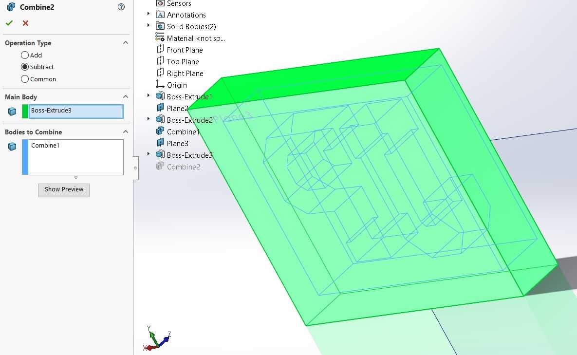
The silicone mold was subtracted from the bounding box using the combine feature as before.
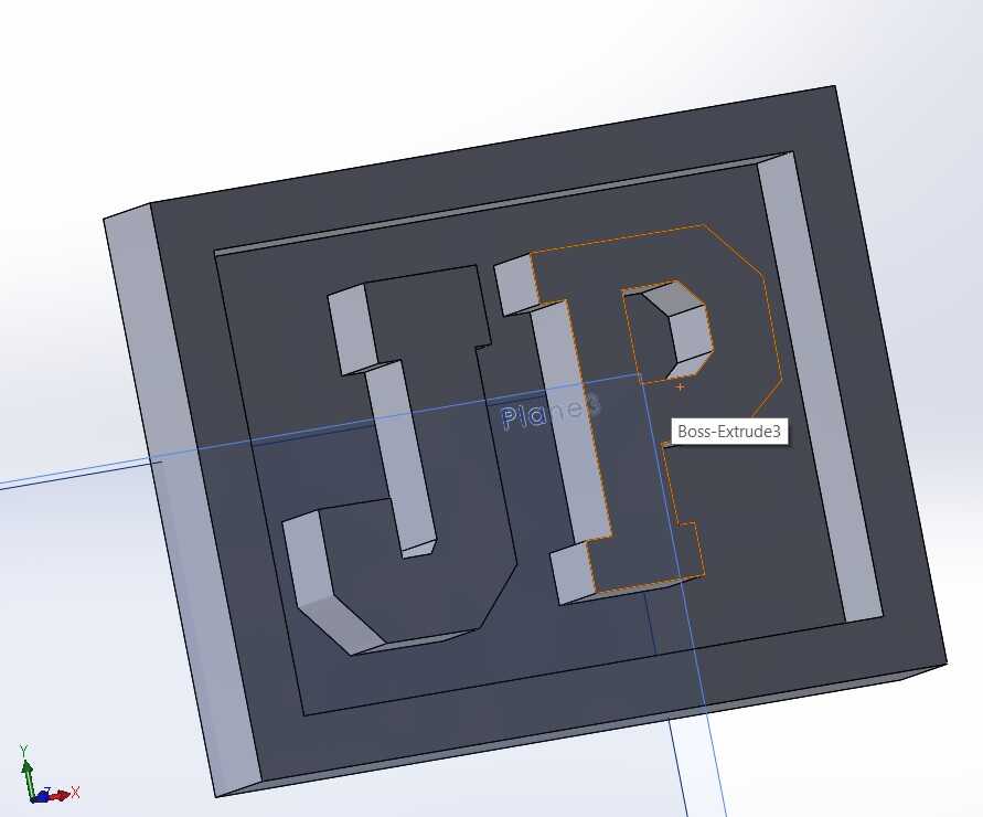
This is how the plywood mold CAD looked like. This CAd file was saved as an stl which would be used in the CNC router for milling.
It was time to get into action mode.
Plywood mold creation
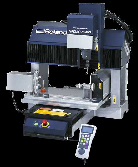
Roland MDX-540
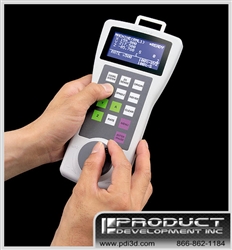
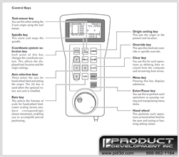
Our AKGEC Fab Lab has Roland SRM-20 for molding and casting. Since this machine was down so I explored another machine Roland MDX-540 at the place where I work for molding and casting. I made myself familiar with this machine. This CNC router was very similar to the CNC router that we had used during the make something big week so it wasn’t difficult to follow. This is a CNC router with a teaching pendant. The three images below have been taken from the internet.
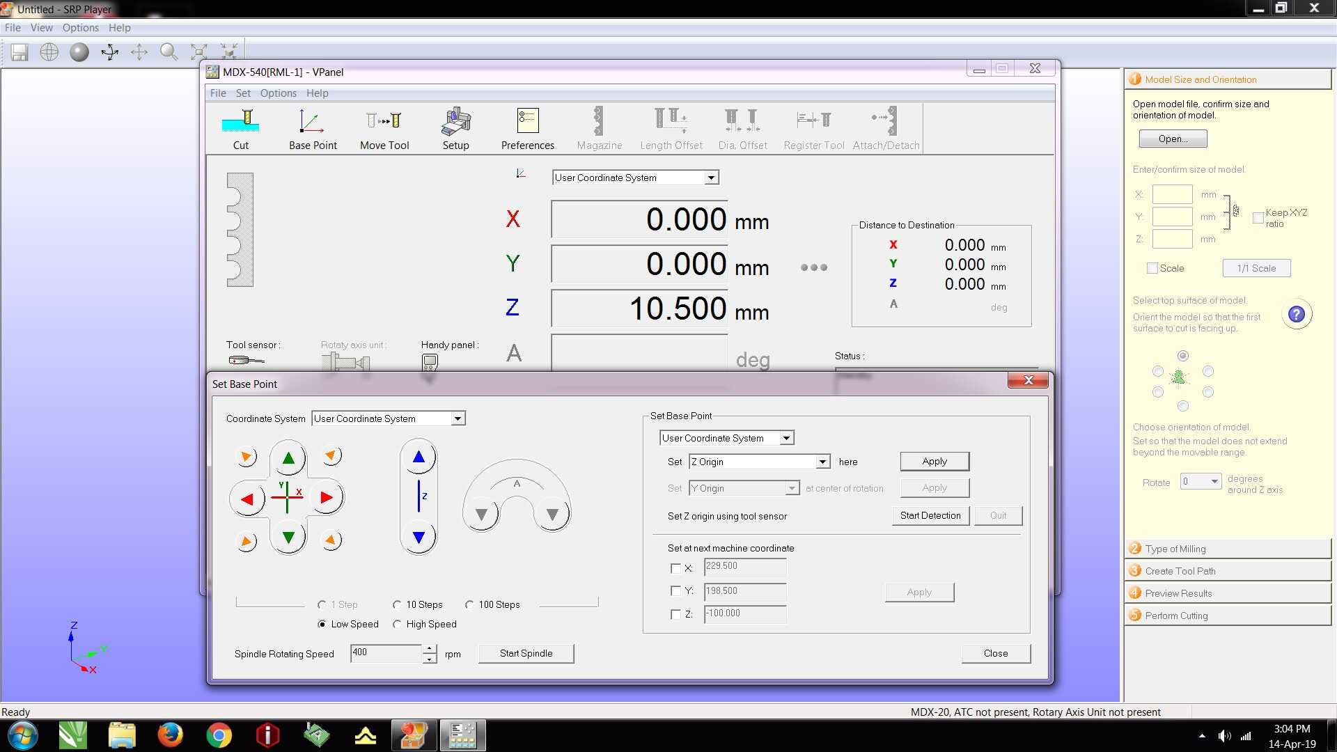
V Panel Modela Pro II software
We use this software to set the origin. Base point is clicked as per the image below. The teaching pendant is used on the machine to bring the tip of the end mill to the point on the workpiece which should correspond to the X, Y and Z coordinates. We click on set origin in the base point window for X, Y and Z and hit apply.
Plywood mold with SRM Player software
SRM Player software is used with the Roland MDX-540 to set the workpiece for cutting.
Firstly, the stl of the CAD file was opened and the dimensions were adjusted based on the considerations of size and time taken.
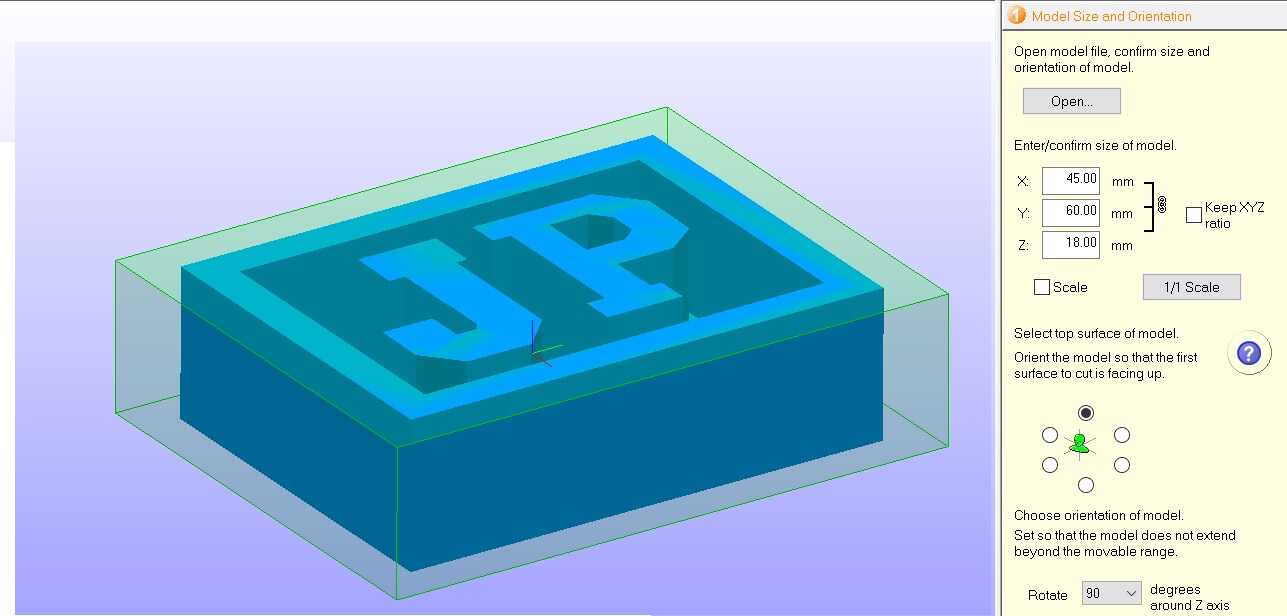
Since this was the first time for me to be molding and casting, so faster cutting time setting was used.
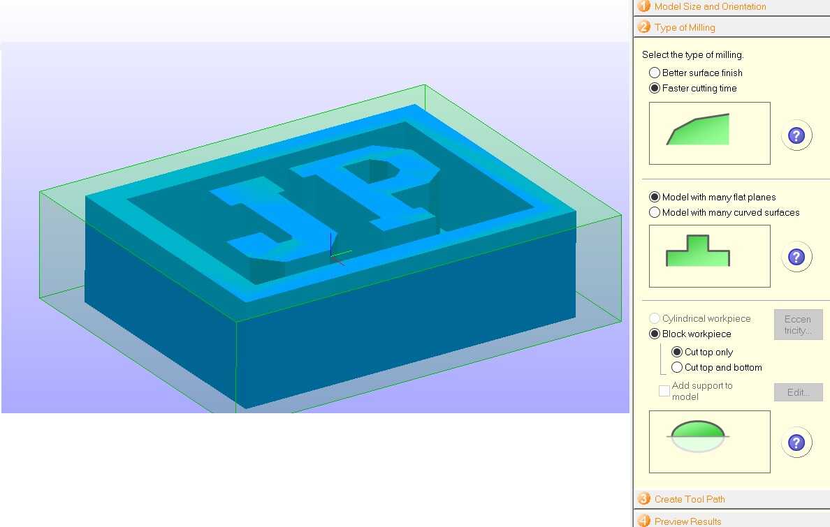
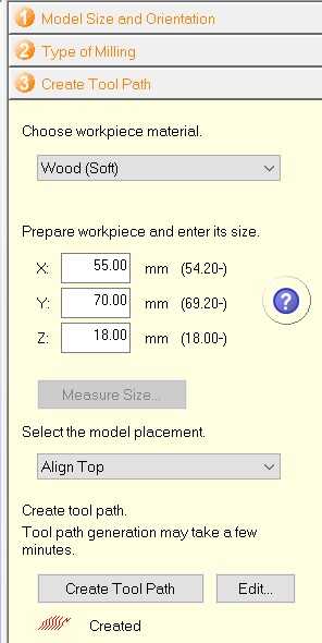
The size of the bounding box was decided here. Then the tool path was created.
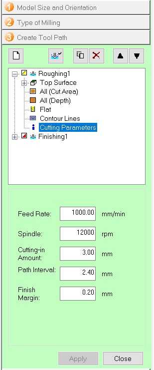
This shows the settings used for roughing operation, especially the feed rate and cutting in amount or depth of cut.
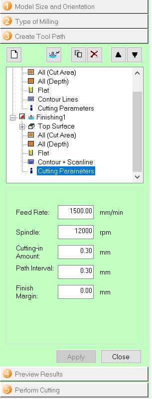
This shows the settings used for finishing operation.
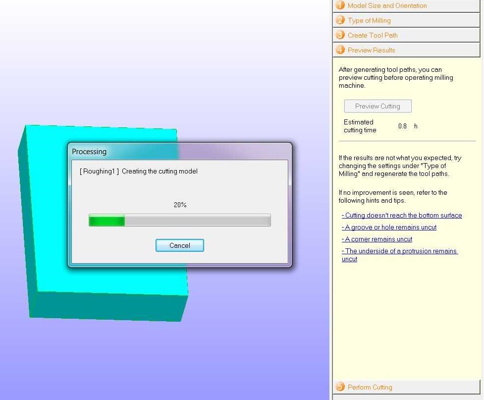
The preview shows the final outcome of the mold based on the above settings. If there is any discrepancy then the parameters need to be changed.
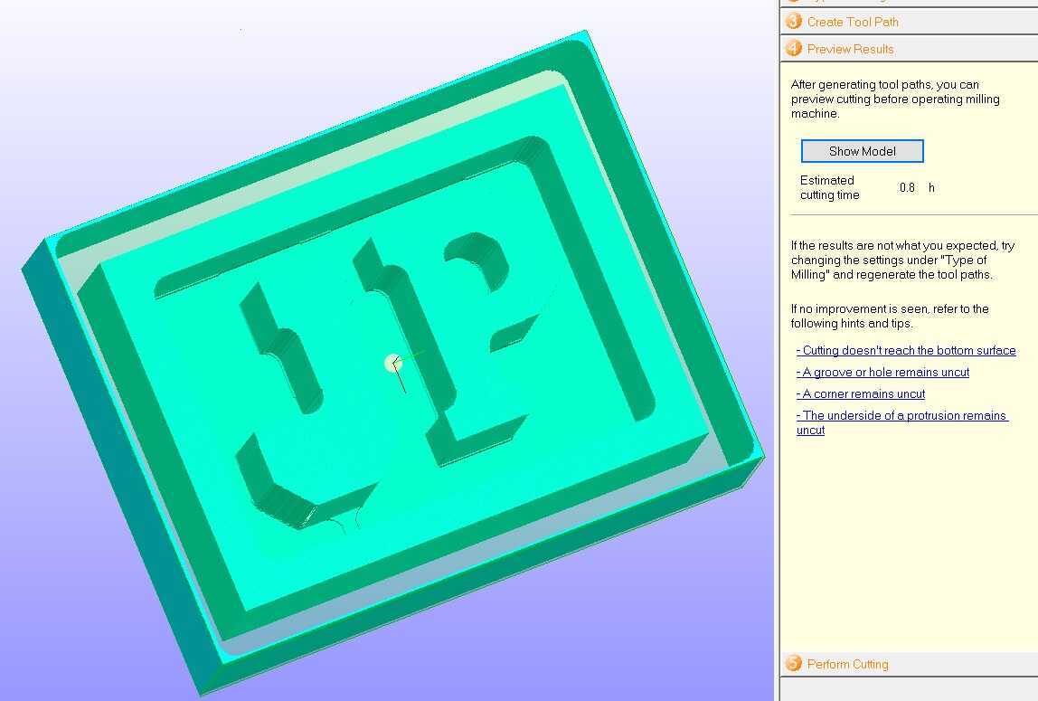
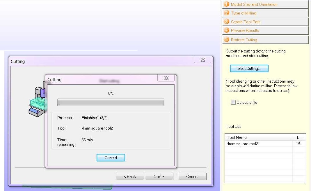
The cutting is carried out with a 4 mm square end mill and the roughing happends before finishing. The total estimated time of operation is 0.8 hours.
The finishing takes more time than roughing.
The following video shows the cutting on the cnc router for my plywood mold.
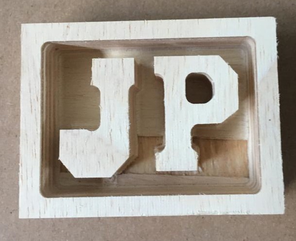
This image shows the plywood mold. The mold has come out really well. The finishing operation has really smoothened out the features.
Silicone mold creation
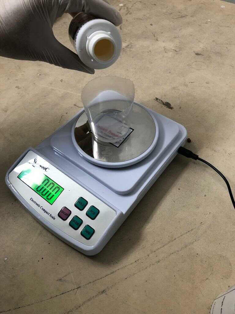
We were suggested to use Aditya silicone rubber RTV 1010 with the curing agent by our remote instructor. This is relatively cheaper and locally available in India. We need to mix 35 gm of curing agent in 1000 gm of silicone. The curing time is 24 hours.
We used a weighing scale to measure the components and mixed them well for 5 minutes.
After mixing, the solution was poured into the plywood mold.
The solution was kept for curing for 24 hours. The plywood had openings in places which led to leakage of some of the mold. It would have been better to tape the plywood mold up to avoid this issue. After curing, it was somewhat difficult to take silicone out from the plywood mold. But due to silicone’s elasticity, it did come out.
The excess silicone mold was trimmed.
Epoxy cast creation
We were suggested to use Haksons epoxy resin and hardener by our remote instructor. The resin and hardener was mixed in the ratio 2:1 as per the instructions given on the bottle. The curing time was 24 hours.
Next, to make epoxy casts, we applied vaseline in the silicone molds so that it is easier to take the casts out.
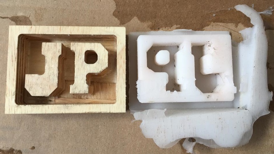
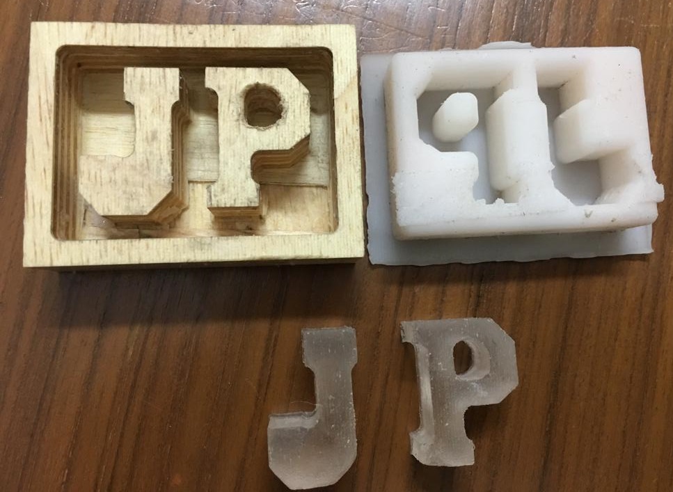
After curing the casts came out very easily. This image shows the plywood mold, the flexible silicone mold and epoxy casts side by side.
Learnings from molding casting week assignment
a. Using the method of Autotrace, any image could be vector drawn to be casted.
b. I did miss out on creating a bounding wall around the letters J and P so that my flexible silicone mold could have had some thickness. I would keep that in mind when I do more molding and casting work.
However, this issue didn’t cause problems with the way my cast came out although I was extra gentle to take the cast out. What I really liked was how flexible the silicone mold was.
Infact, to correct myself, I created another silicone mold by adding a thick wall by wrapping acetate film around the wood mold as per the image below.
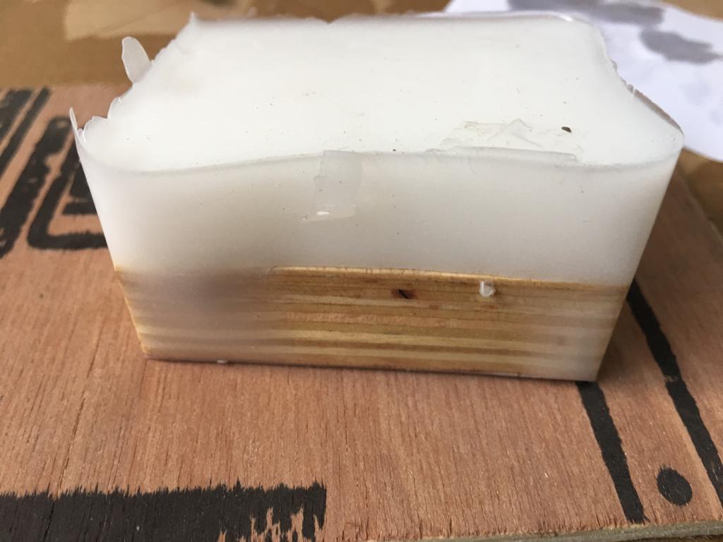
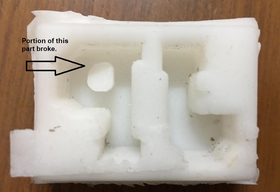
But there were two downsides to it. The extra wall height of the silicone mold made it difficult to remove it from the plywood mold. I was not very gentle as I thought that silicone is very flexible so the column inside the P tore up a little. This suggests the need to be gentler and not have excessive depth with such small corners.
c. This was the first time when I was doing molding and casting hands-on. I didn’t think of giving draft angles i.e. taper perpendicular to the parting line. I should have given a positive draft angle such that the taper increases towards the outside which makes it easier to take the part out.
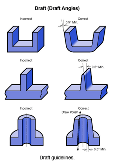
This image has been taken from this source.
Thanks to my global evaluator Daniel and my remote instructor Puneeth for bringing this up. I would keep this in mind for future to include them.
d. I started off by wanting to make a cup with a handle which seemed to be difficult since the process required primary mold making along two axes and ended up letters which I could have easily made with a laser cutter since it is a 2.5D process. My global evaluator, Daniel, makes this important point.
Perhaps, the sort of in between shapes which I could have casted shouldn’t be 2.5D such as chess pieces, bottle, fidget spinner, etc.
Designs
Download for the CAD in Solidworks for the final casted part which is the letters J and P.
Download for the CAD in Solidworks for the silicone mold of our casted part.
Download for the CAD in Solidworks for the plywood mold using the silicone mold of our casted part.
Download for the stl of the CAD in Solidworks for the plywood mold using the silicone mold of our casted part.

Solar powered electric bike con kit by Jay Dhariwal is licensed under a Creative Commons Attribution 4.0 International License