1. Ideation
In this week we have a group project to build a machine so we have decided to make a machine that reflects our culture and the machine is Qatayf machine so basiclly it is just a machine that makes Qatayef
Qatayef is the Arabian version of Pancake. It is usually served in the holy month of Ramadan. It has a special dough that can be filled with different stuffing such as: cheese, nuts and nutella.

So basically our machine has two axis X and Y controlled by 3 steppers, two of steppers for the Y axis because the main load on it and one stepper for the X axis, so it can move along them as the same as the ShopBot machine but the diffrence is that our machine has an extruder in the Z axis instade of the spindle so it can make many shapes of Qatayef.
After we finished the discusstion about the machine we went to the second part, its about the initial sketch fr the machine and how we seperate the tasks for each one of us.
my tasks in this week is to :
1.Design the extruder which is the z axis of the machine .
2.Controll the stepper motors.
So here is the initial sketch of our machine

2. Mechanical Design / Extruder
Before starting the design I want to demonstrate further about the workflow of the nozzel.... the mechanism of the nozzol is so simmilar to the piston so we have a nozzel contains the raw material of Qatayf and a shaft press the material to flow shown

And the vertical force that acting on the piston caused by transmitting the rotation motion of the extruder stepper to a linear motion in the leadscrew as the same as the bed lead screw in 3D printers

In my design I want to make two lead screws and the lead screw nuts are connected with a piece of acrylic so the piece of acrylic will move up and down by the lead screws, after I will connect the shaft of the nozzel piston with the acrylic piece so I can controll the extrusion procss
I star the design using SolidWorks software Since it my favorite CAD software, the first thing I start with is the nozzel since we have bought it

In order to avoid mistakes in the real assemply of our machine we have to make accurate design, so we will design every single piece of the machine and here is the nozzel design.

After I got the nozzel design I want to start designing the extruder, the motor that used in my extruder is NEMA 17 stepper motor, in order to import the design of the motor I went to grabcad so I can fined many parts like the lead screw, nuts, motrs, and many

Right now I will design the holder arm of the motor and I will use 3D printing to manufacture this part

As shown in the next picture I chose the same printing variables using ultimaker 2+
Printing material is pla
nozzel 0.4mm
Layer hight 0.2mm
infill 20%
wall and top/bottom thickness 1mm

Download the file sld part or stl part
Now I start designing the gears in which they will make a led screw rotates, the first gear is the driver so the center hole should be as the same as the diameter of stepper motor shaft and here is the main gear - driver

since the driver gear designed I have to design the driven gear and here is the driven gear

download the driver gear and driven gear
Because I dont want to wast and the 3D printer takes alot of time I made the gears by the Trotec speedy 400 laser cutter and the material was acrylic of 10mm thickness and the cutting variables are :
Power 100%
Speed 0.15
Frequency 55k
Lens focal length 1.5"
After I started the design of the nozzel holder

As the same as the previous way of the gears using laser cutter I made this part but here the laser cutter is not enough, I need 3 axis machine in order to make the two pockets in this part so instade of 3d printing and 6 hours of waiting I have done the pockets with Tormach PCNC 1100 with comparing in 3d printing here and all the setup and machining time for laser and Tormach takes less than one hour.
In order to lunch the milling machine I have to get the G code so I used Fusion 360 CAM process to generate the tool path

and this is the cutting variables

I used 4 flutes 3/8" end mill to make faster feed rate .

and here is the pocket


Download the file sld part
Next I designed the part that will push the nozzel down

and I made this part by the same way of the previous part so this is the file sld part
in the above design I want to plug in a lead screw nut in order to make the rotation of the lead screw to linear motion so I got pre-designed lead screw nut and bearing of 8mm


After I have designed the parts I went to my favorite part assemply
I used many mates, in the basic mates I used coincident

as shown here I used coinsident mate between the nozzel and the nozzel holder in order to privent the free motion of the nozzel also I used many mates like the mechanical mates - screw between the lead screw and lead scrw nut also gear mate in the mechanical mates between the gears
and here is the final extruder after assemply

This video shows the how the mechanical mates are usefull
Download the extruder sld assemply
After I finished the extruder I made another assemply with the machine that each one of us finished his/her part in it.
In order to fix my extrder in the machine I have made a design and I called it Z axis holder in order to make my extruder fixed with the machine I used two pieces of the Z axis holder

Download the file sld part
I have made the 4 small holes to join a new part to my extruder and this part is the rod slider in order to make the extruder fixed and moves smoothly along the two rods and here is the sider


Finally this is the final assemply :D

Download the machine assemply sld
In order to move the X axis of the machine we used a belt connected with stepper motor and the Z axis holder by two added holes

And this is proof of the X axis automation
In other hand my friend Esraa designed another extruder just to have a back up plan in case if a problem happend

3. Controlling The stepper motors
After we finish the machine design last week we have to automate it, in our machine we have 4 steppers so we need 3 drivers for the axis, one driver for two motors for Y axis, one for X axis and the last driver for the extruder, we used Pololu a4988 stepper motor drivers which will mount on CNC Arduino shield v3

This tutorial show how to use the shield like how to connect the y axis motors in one driver and how to controll the microstep for each motor and the firmware that we used for the arduino uno is Grbl.
For Flashing Grbl to an Arduino we folowed this tutorial .
After we flashed the firmware to arduino IDE we used Universal G Code Sender to interface and controll the motion of the machine, so this interface recieves the G code.

for example if we want to make a circular motion in X and Y axis f the machine we type the g command G03 X0 Y5 i5 j0 f50 this g code order the machine to make one CCW rotation and the diameter of the circle is 5mm and the feed is 50 mm/min, so by this software we will interface the machine but before start moving the axis we have to make a calculation for the motor and the lead screw in order to make the machine acurate for example if we type this command
G91 G00 X10 Y50 this command order the machine to move a rapid motion from its position considering it as the zero by 10mm in X direction and 50mm in Y direction BUT how the machine will know that it moved 10mm ?? the answer is there is a relation between the number of rotation of the motor and the lead screw, in our machine we have NEMA 17 which has a step angle of 1.8 from the data sheet, It is important to know how to calculate the steps per Revolution for the stepper motor because only then you can program it effectively.
Steps per revolution = 360/step angle
Here, 360/1.8(from data sheet) = 200 steps per revolution.
My friend ISRAA did this calculation for the axis
Y axis Calculation
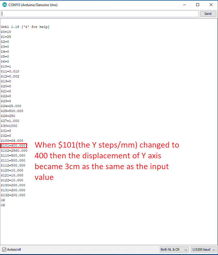
In Y axis we used screw mechanism with 8mm pitch. To find step per mm I used this formula: Step per mm = (Motor steps per revolution * Driver micro steps) ∕ screw pitch Step per mm = (200 * 16) ∕ 8 = 400 step∕/mm.

Z axis Calculation
Also in Z axis, we used screw mechanism but with a pitch equal to 1.25mm. To find step per mm I used the previous formula: Step per mm = (Motor steps per revolution * Driver micro steps) ∕ screw pitch Step per mm = (200 * 16) ∕ (Belt pitch *Pulley number of teeth)= 2560step/mm.
X axis Calculation
In X axis we used pully and belt mechanism our pully has 25 teeth and the pitch of the belt is 2mm. To find step per mm I used this formula: Step per mm = (Motor steps per revolution * Driver micro steps) ∕ (Belt pitch *Pulley number of teeth) Step per mm = (200 * 16) ∕ (2 *25) = 64 step∕/mm
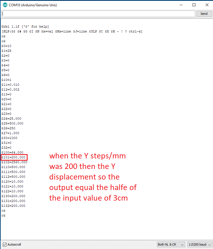
After we make the calculation we edited the Grble from the serial

each axis has a number so after we got the step/mm we edited them.
Finally this is our Qatayef machine :D
4. Problems
yes I had a problem, the load on the extruder stepper was very high and it couldnt move why??
Because I didnt fined a lead screws to transmmit the motion is I used a threaded rod M10 and two nuts so waht happened because
The lead screw used for the dynamic load so it has low friction coefficient to make the load moves smoothly along it.
And the threaded rod M10 and the nut that I used is for the static load so it has high friction coefficient

also we can noticed the ramp angle of the lead screw so it makes the movement easy any way in my design I used two threaded rodes so more friction but we have to make the extruded works!! so my friend ISRAA has worked an extruder with one threaded rod to reduce the friction also we reduced the mass of the extruder by making it 3d printing instade of the heavy acrylic
5. Opportunities For Improvements In The Design
In the future, when I have time for the improvement I will try to increase the machine rigidity, our machine has a 3d printed parts for example the left and right holders are 3d printed so I can make those parts by tormach metal milling CNC

In order to make the motion more smoothly for the machine I want to design and mill the parts with aluminum 6061 since it has less weight compareing with outher metals and its better to change the stepper motors to a steppers that have a higher tourqe.
For the nozzel Im thinking to design and add external supply for the cream, because the nozzel cream volume is not enough and everytime we want to fill the nozzel we have to remove it then fill it so its a hard process.
During the machine week we did not have enough time to make a board so we used arduino and in the future we will use our board and add LCD for the bed temperature.