you maybe ask a question, what is AVR?
AVR is a family refers to Atmel for example Samsung has many smartphones fmilies, such as Note, Galaxy S and bla bla bla, so Atmel has many families, one of them is AVR, and one of the best example for AVR chips is Arduino boards, we can see all Arduino microcontrollers mega, Due, and Uno all of them have AVR microcontrollers
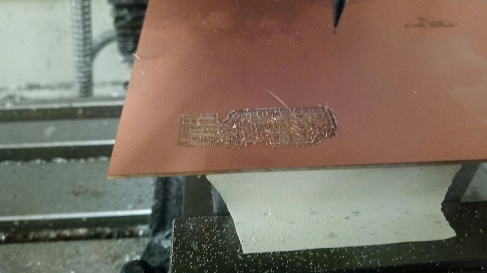
The first thing that we are going to do is to make our ISP using Roland SRM-20.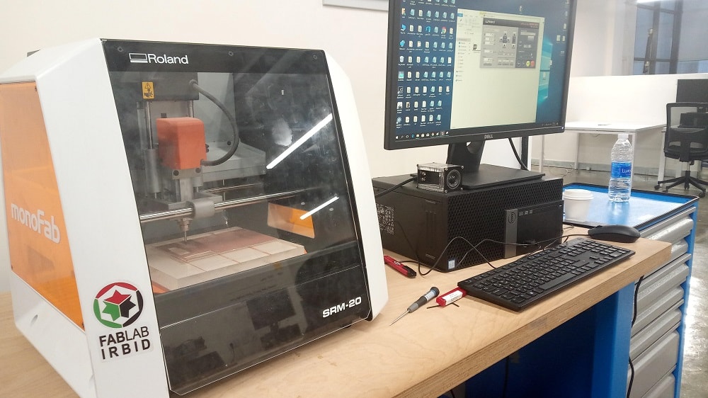
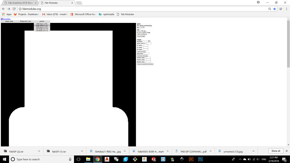
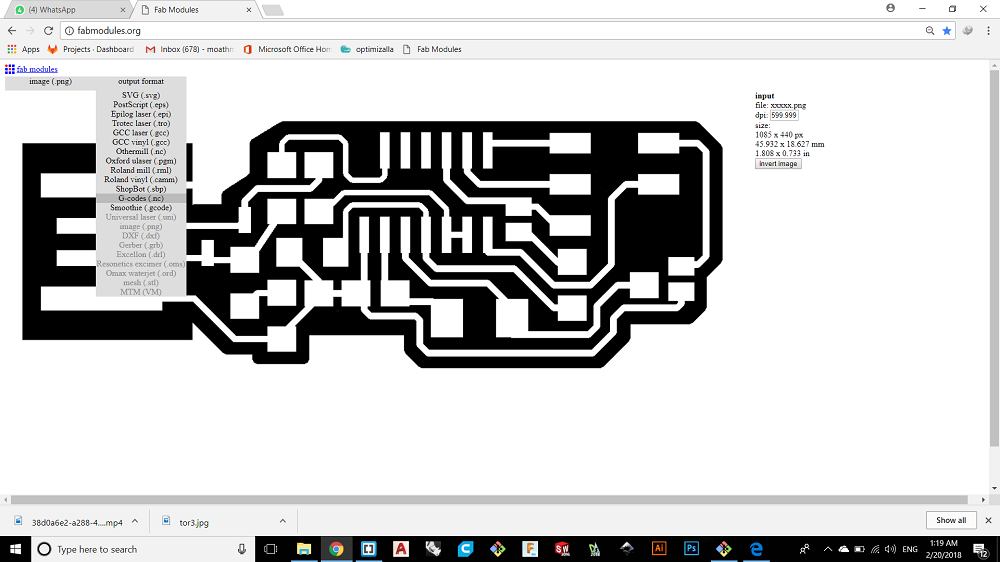
In this week we will start and introduced to Fabmodules to generate the tool path of our ISP utilizing a ready taken photo for the ISP.
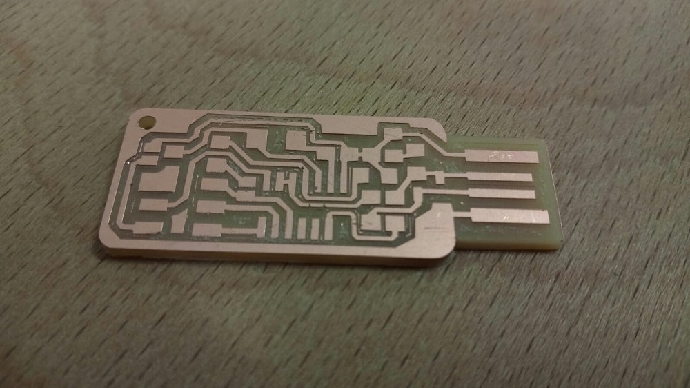
There are two pictures to make two cutting operations, the first one is the inside cut for traces and the second one is for the outside cut to get the piece out of the stock.
This is the inside and out side pictures

You can Download the files here FabISP
I uploaded the inside cut for traces first to the website by choosing image.png.
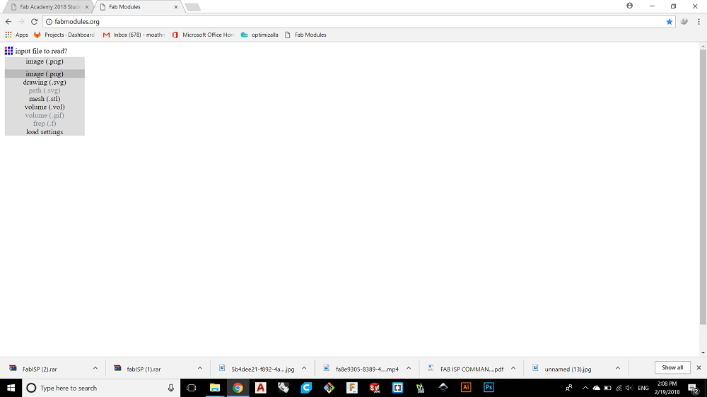
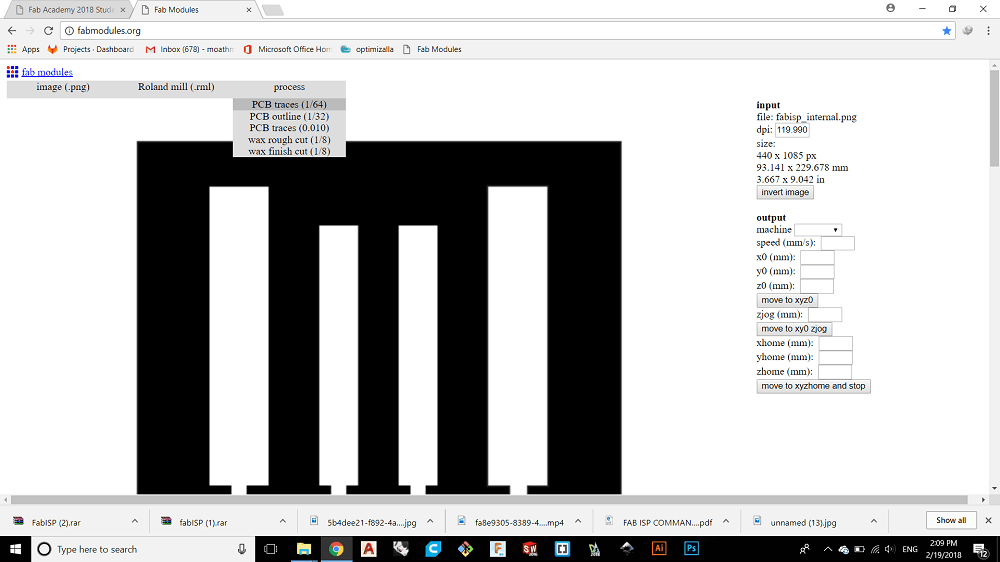
Then from output format I chose the machine type which is Roland mill.
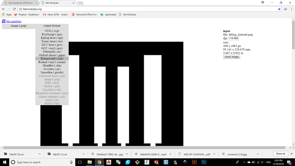
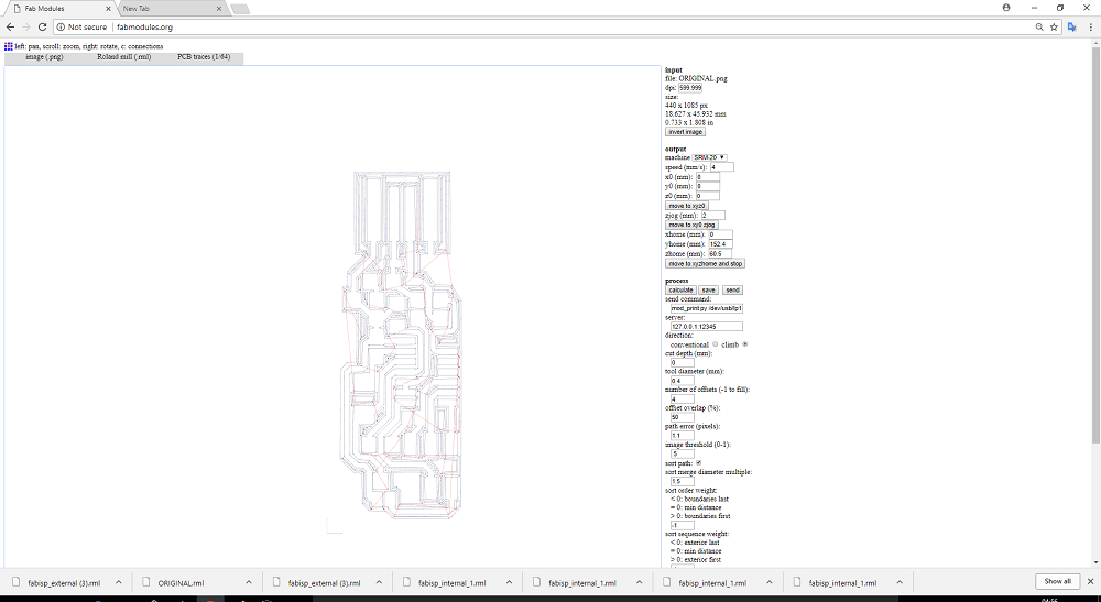
Here I will set the cutting variables like cutting speed (feed), R.P.M, offsets, stepover or overlap, the tool diameter ....etc.
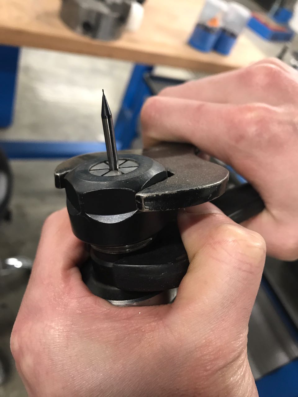
The tool diameter for the inside cut will be (1/64)" and the feed is 4mm/s - it needs to be slower for the outer border of the PCB since it will cut through so we need to reduce the speed to minimize the resistance, otherwise the endmill will break and we don't want to waste a lot of time and money!
x0,y0,z0: coordinates, all were set to zero.
Cut Depth: it was set to 0 since I just need the machine to scrape the surface of the copper sheet.
Number of offset 4 - this is set to have the separation between the traces wider making it easier to solder.
Offset Overlap: 55% - in any milling operation the overlap or the stepover recomended to be at maximum 60% of the tool diameter to get good finish.
we press calculate and the tool path will be generated.
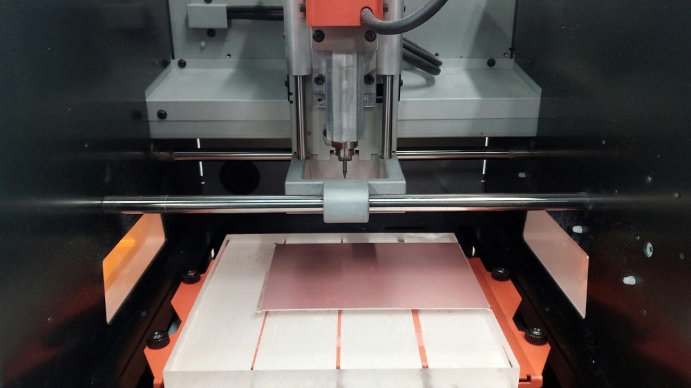
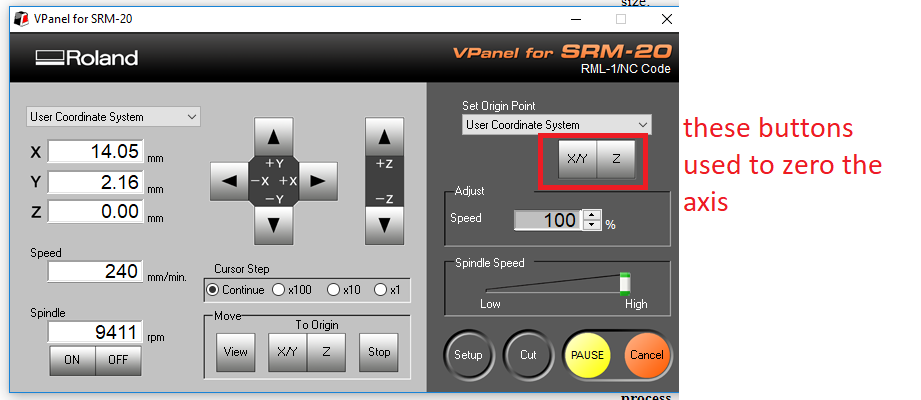
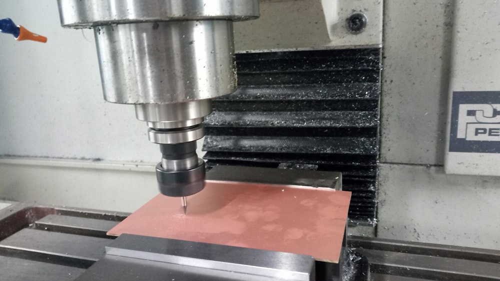
Now its time to start milling using Roland SRM-20 to mill my board, the interface software is Vpanel.
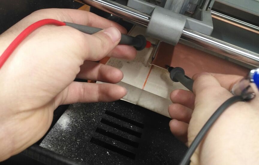
to zero the Z axis I make the cutting tool touch the plate by dropping down the z axis using vpanel and I used the avometer to make sure that the z axis touched the plate
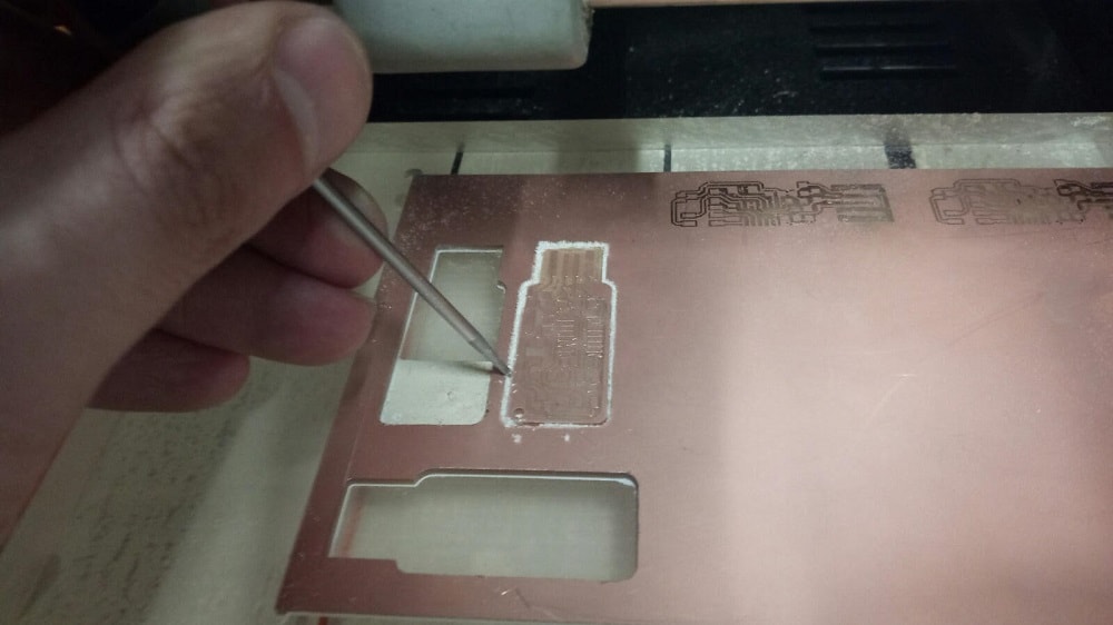
This is the board
After the inside cut finished then we will start the outside cut but we change the tool to a bigger one (1/32)" and we lower the feed from 4 to 1 and the depth of cut from 0 to 1.8 mm, with considering the thickness of the board so if you have 2mm of thickness board make the depth of cut 2.1mm to ensure through all cut .
after that we remove the board carfully.
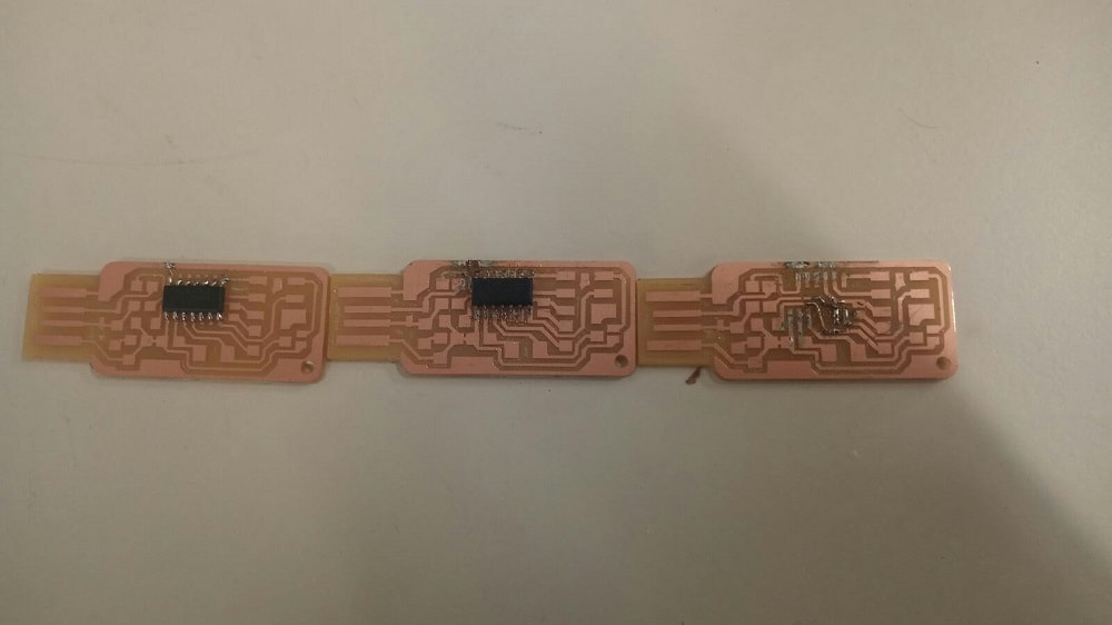
And this is my first board :D
The second thing to after milling and before brograming is soldering the components, I took the PCB design files, images for tracing and cutting fromHere.
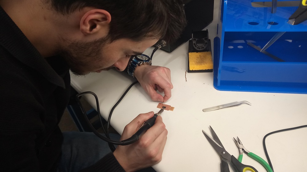
After soldering for the first time I faild tow times :P, soldering is not that easy
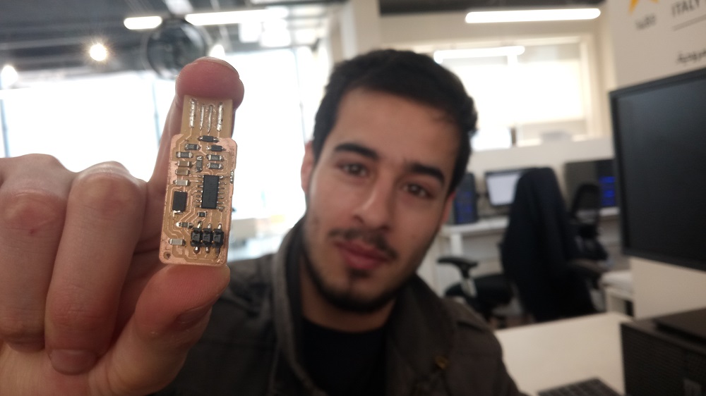
finally this is my final ISP :D
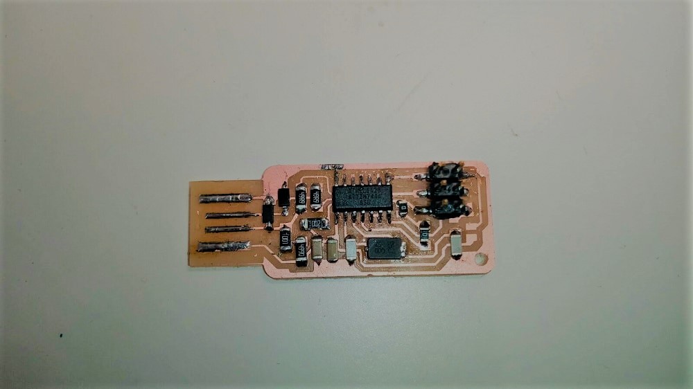
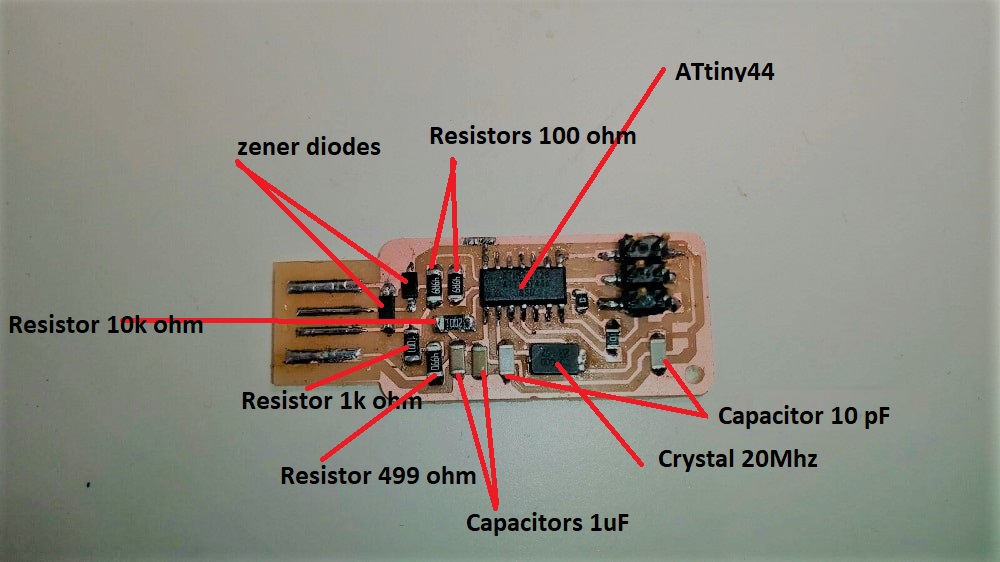
The components that I used are: 1 ATTiny 44 microcontroller
2x 3.3V zener diodes
1 Capacitor 1uF
1 Capacitor 1uF
2 Capacitor 10 pF
2 Resistor 100 ohm
1 Resistor 49 ohm
1 Resistor 1K ohm
1 Resistor 10K
one 6 pin header
1 Cystal 20MHz
After that I tried to mill a board on tormach pcnc 1100.
So from fabmodule web site we choose the output format is G-code.nc this is the only diffrence.
then I used the same bit on roland SRM-20
to zero the Z axsis I usd the avometer to avoid tool breakage.
the final result was not so good
because the maximum R.P.M of tormach p1100 is 5000 rpm so if we calculate the rpm of 1/64 it will be more than 5000 and the maximum rpm of the roland is 10000 so t gives a better surface finish.
The third section in this weekly assignment is programming the ISP.
For programing you can use Windows,IOS or Linux so it is better to use IOS or Linux for programing, I used Linux Ubunto virsion.
I have Windows on my laptop so what I did to get linux Ubuntu is install it on a USB drive, so I can use ubuntu any time I want by entering the USB in my laptop also you can watch many tutorials on youtube.
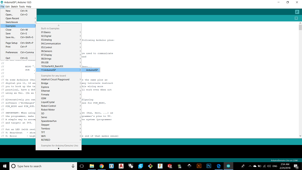
To program the ISP I used arduino uno so the arduino will programe the ISP, to do that I installed Arduino aoftware to instal the code on the arduino uno. There is already existing labrary (Examples) on the software so I used Arduino ISP as shown.
Then I plugged the the arduino with the USB by a cable and I checked that the arduino is connected well by seeing the port defined as arduino as shown in the next pictures.
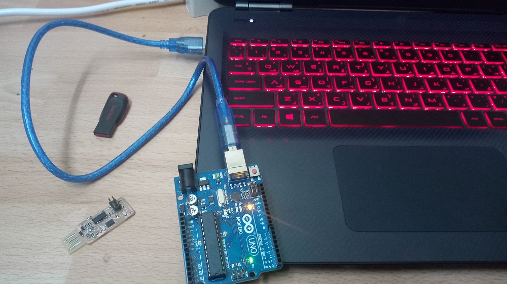
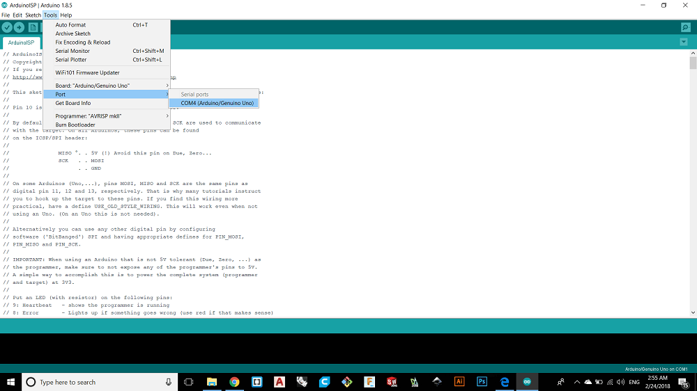
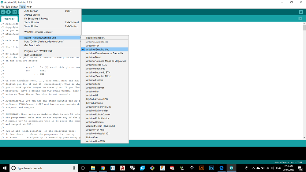
And then I checked the type of arduino
then I clicked on the upload button and waited untill the upload is finished.
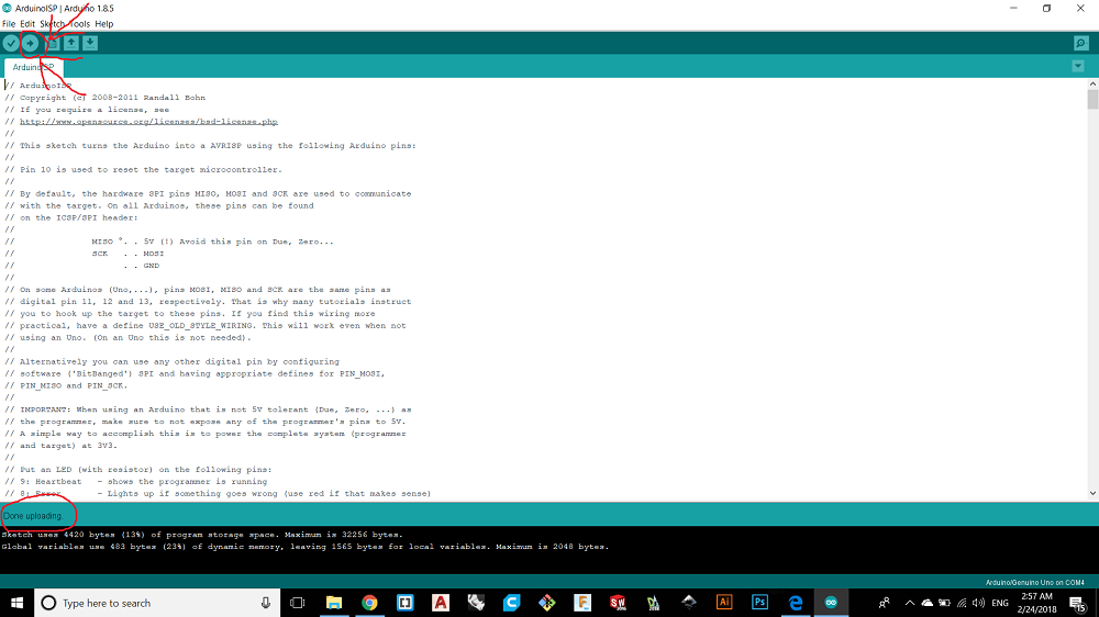
Now the arduino become a programer.
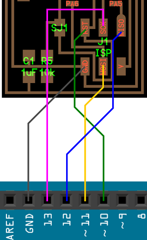
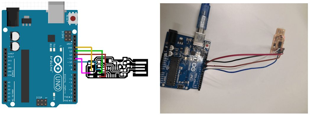
Now its the time to make BURN BOOTLOADER, If you have a new ATmega328 (or ATmega168) or as in our case ATtinny44, you'll need to burn the bootloader onto it often called firmware.
You can do this using an Arduino board as an in-system program (ISP) like I did before.
To burn the bootloader, follow these steps:
1- Upload the ArduinoISP sketch onto your Arduino board. (You'll need to select the board and serial port from the Tools menu that correspond to your board.)
2- Wire up the Arduino board and microcontroller as shown in the diagram to the right.
3- From tools select the board "ATtiny 24,44,84 and the processor ATtinny 44, usaally you need to install the library of ATtinny 44 because you will not find it.
4- Select "Arduino as ISP" from Tools > Programmer
5- Run Tools > Burn Bootloader
6- You should only need to burn the bootloader once. After you've done so, you can remove the jumper wires connected to pins 10, 11, 12, and 13 of the Arduino board.
Now it is the time to start with Ubuntu, to get ubuntu I made it bootable USB drive on my windows 10, after I opened ubuntu from my USB drive I connected the internet and started the following important steps to update the system.
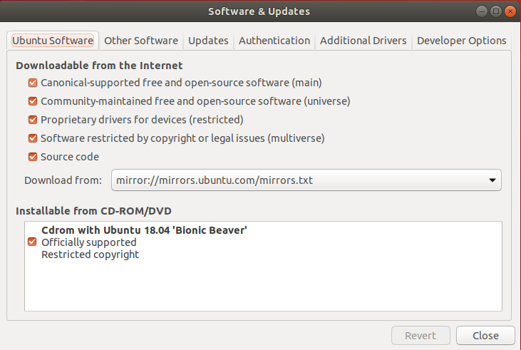
1. Open Software and Updates by searching for it in the Dash.
2. Open the "Ubuntu Software" tab.
3. Ensure that the first 4 check boxes on this tab are enabled as shown
4. Press ctr+alt+T to open the terminal and update the package lists, then test with these commands:
sudo apt-get update
sudo apt-get install flex byacc bison gcc libusb-dev avrdude
If you followed the above and tested the second command you should not get this ###### E: Unable to locate package(byacc)######
After I finished the updating process I commented these comments to instal install the necessary drivers and packages.
1- sudo apt-get install flex byacc bison gcc libusb-dev avrdude
This code is already commented to test the packge so no need to comment it again.2- sudo apt-get install gcc-avr
3- sudo apt-get install avr-libc
4- sudo apt-get install libc6-dev
A- The sudo command allows you to run programs with the security privileges of another user.B- gcc compliler used to translate the sorce files in C language for AVR microcontrollers.
C- Advanced Packaging Tool (APT) performing such functions as installation of new software packages, upgrade of existing software packages, updating of the package list index, and even upgrading the entire Ubuntu system.
D- libc6-dev contains files used by the compiler to build software using the C library.
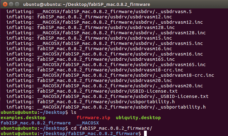
The following commands are to download the firmware
5. cd ~/Desktop
wget http://academy.cba.mit.edu/classes/embedded_programming/firmware.zip
unzip firmware.zip
Now its the time to plugging our ISP in to the arduino. 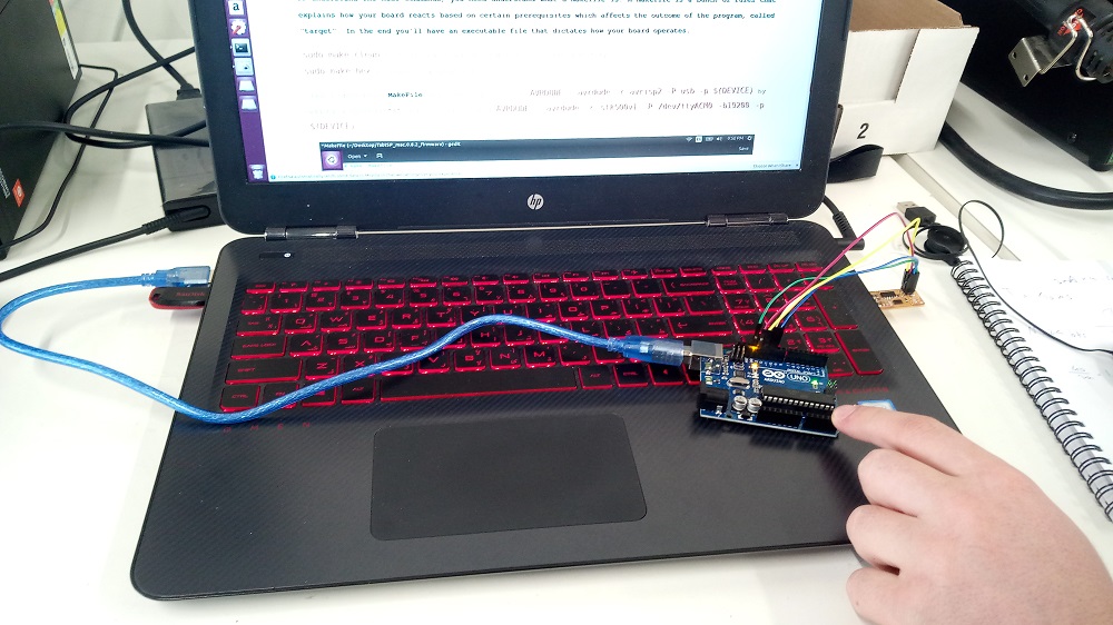
After that I entered the firmware folder by comminting these coments
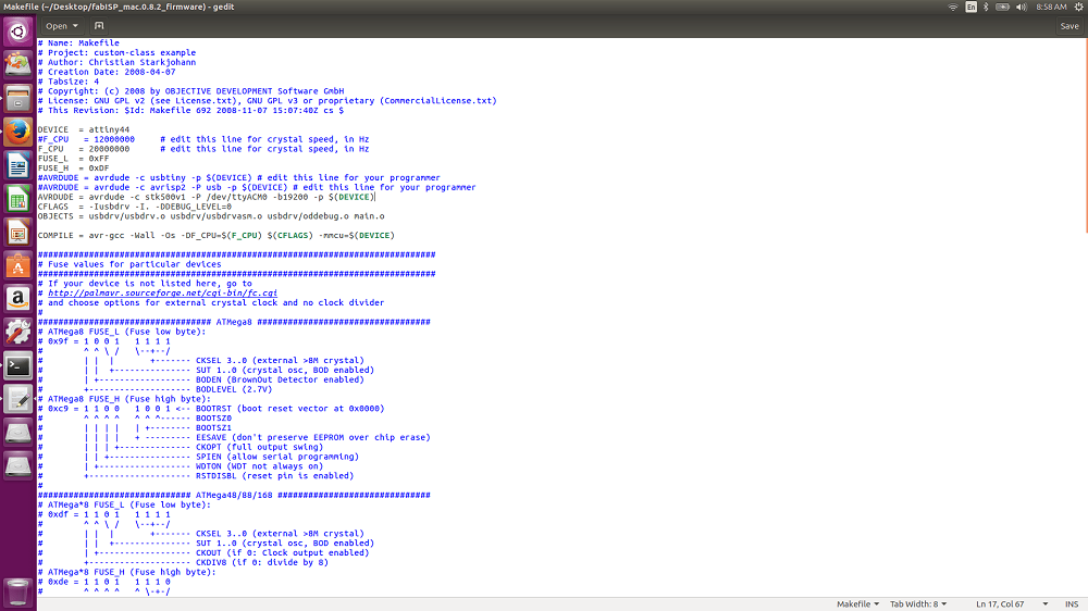
To understand the next commands, we need understand whatis makefile:
Makefile is a program building tool which runs on Unix, Linux, and their flavors. It aids in simplifying building program executables that may need various modules. To determine how the modules need to be compiled or recompiled together, make takes the help of user-defined makefiles.
Now we type these comands:
6. sudo make clean
: Deletes existing executable files in the directory.7. sudo make hex
: Creates new updated files.Then open the file makeFile, we have to know here how to comment the codes and that done by adding hashtag # in the start of the line.
so
I commented this line
AVRDUDE = avrdude -c avrisp2 -P usb -p $(DEVICE)
by adding a hashtag "#" Then i addedAVRDUDE = avrdude -c stk500v1 -P /dev/ttyACM0 -b19200 -p $(DEVICE)
Then typed:
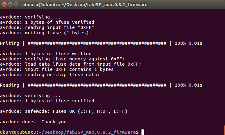
8. sudo make fuse
This links the executable file with the makefile.9. sudo make program
This compiles the program.