1.INTRODUCTION
In this week I am going to use Tormach PCNC 1100 milling machine, its a 3 axis milling machine has max spindle speed of 5000 rpm, to mill a wax rectangle in ordedr to make a mold for choclate.
also I am going to use Fusion 360 cam to generate the tool path.
1.Design
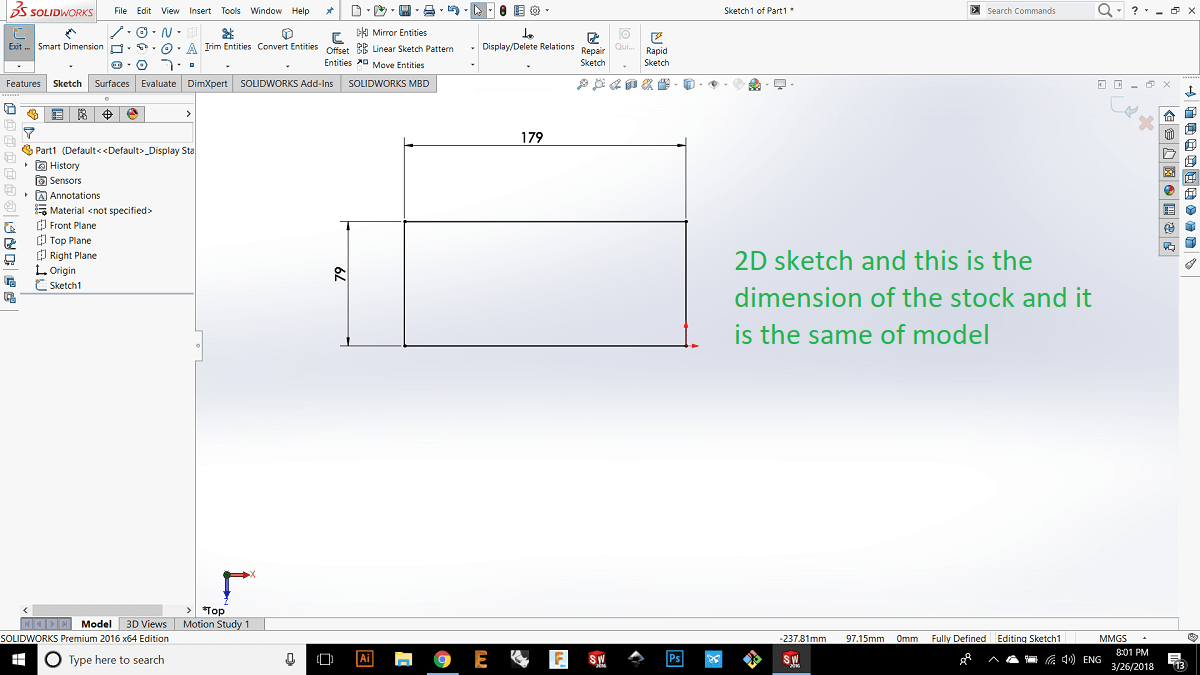
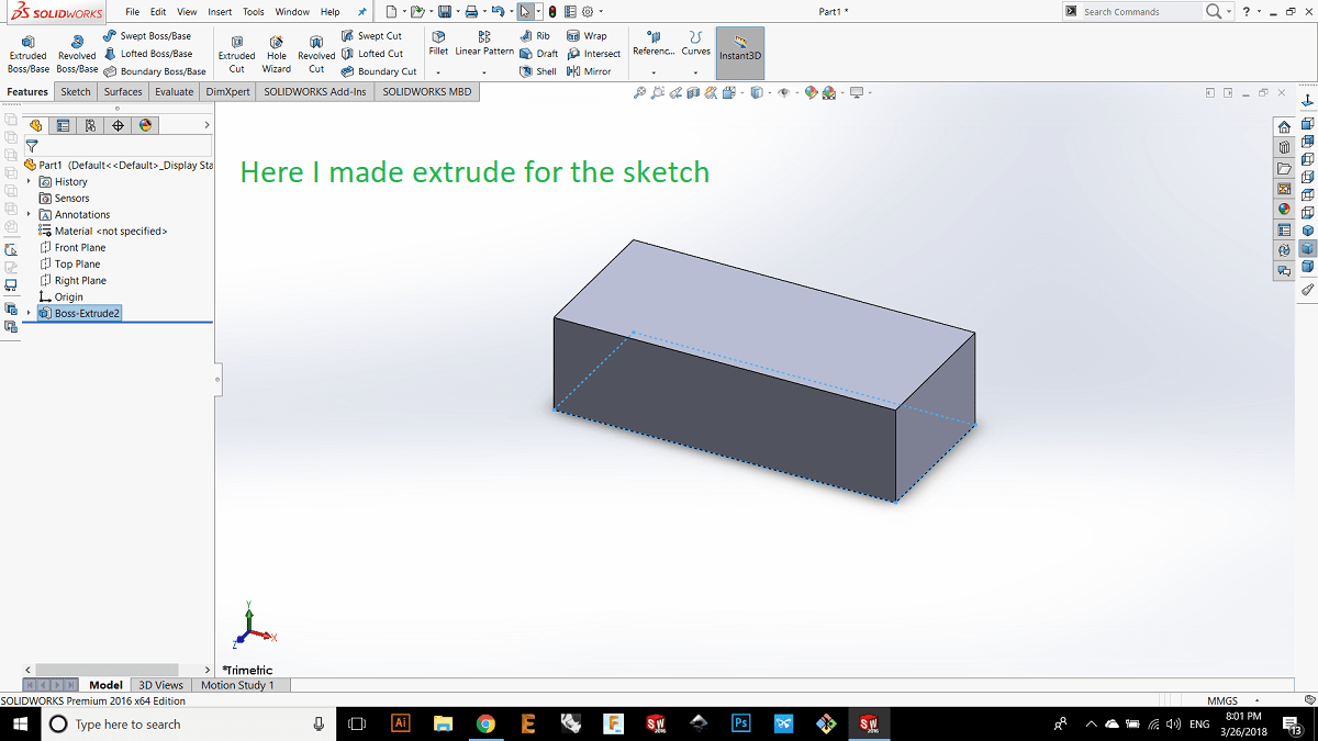
I designed the model using Solid works, I started the design with 2d sketck of a rectangle with the following dimension and then as the same as the wax stock thickness then I made extrude 50 mm.
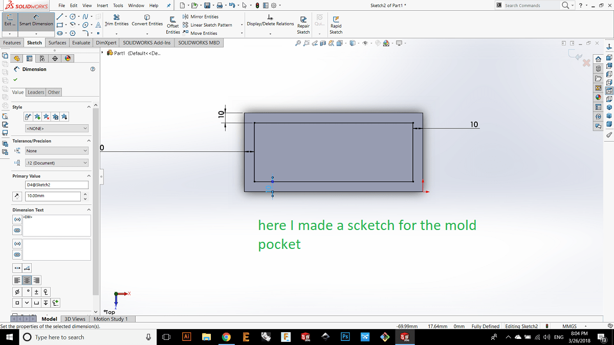
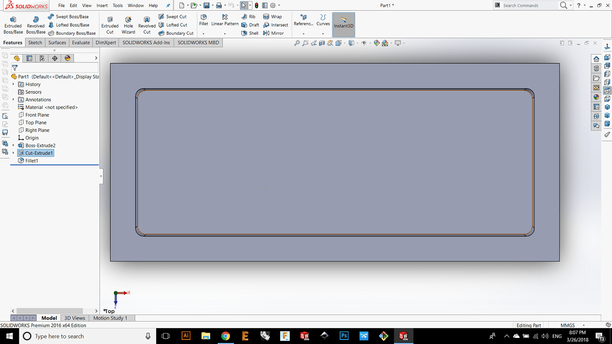
Now I'm going to make extrude cut with a draft angle of 5 degrees to make the ejection process for the die easy so the draft angle should be small in order to reduce the friction.
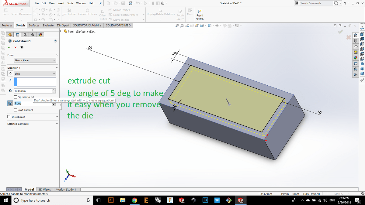
Here you can see the draft angle.
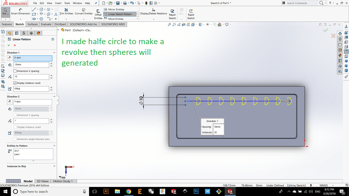
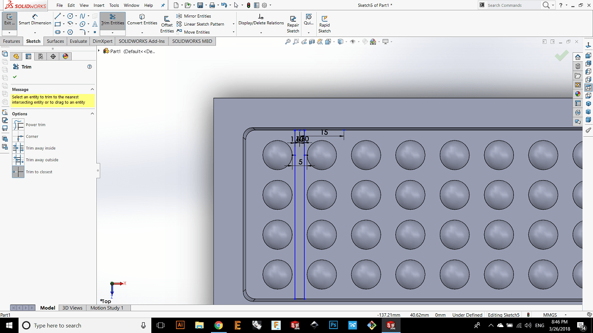
Now I'm going to make the shape of the mold, In solid work if we want to make a sphere we shoud draw a half circle and then use the revolve feature to make the halfe circle revolve around its diameter axis, so after I made a half circle I used sketch pattern in the x direction.
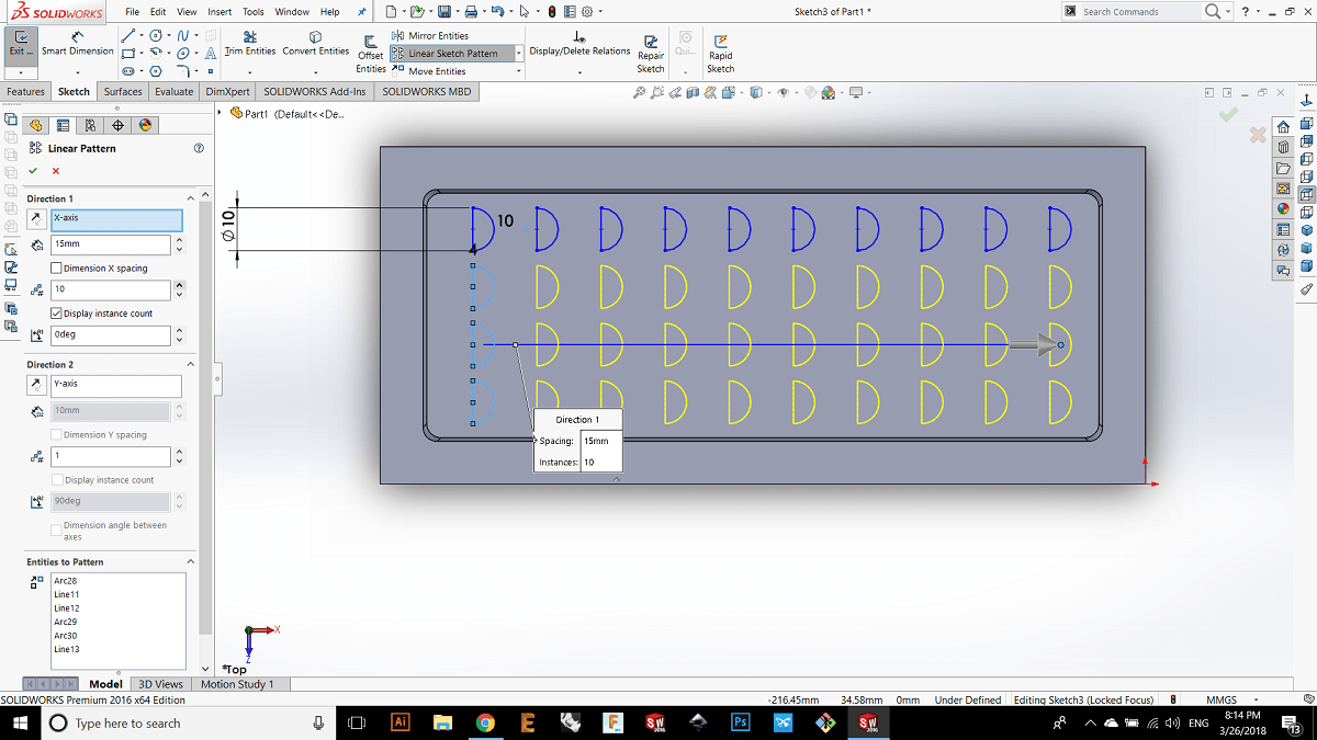
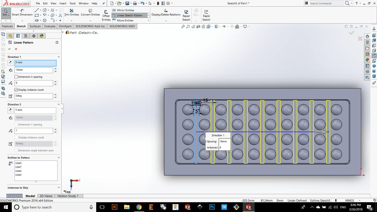
Here I made a sketch pattern on the y direction.
Here I made revolve to generate the spherical shape.
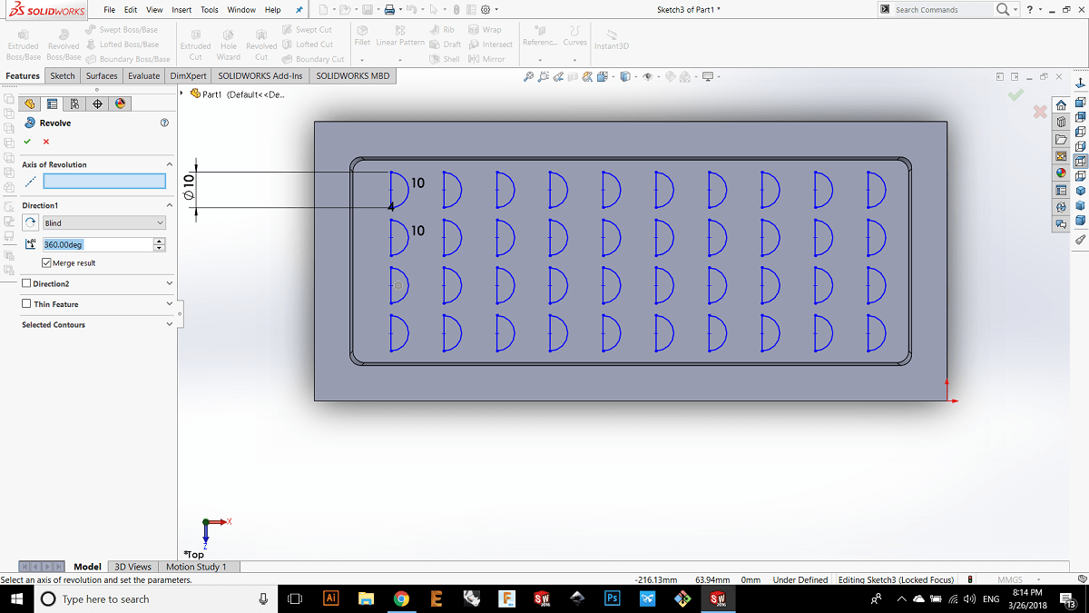
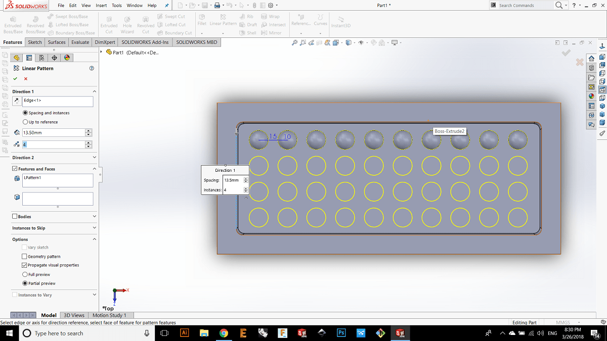
I noticed that I cant make a revolve for all halfs so I have to make revolve for each half separatly and that needs a lot of time because I have too many spheres, so I decided not to wast time by making just one sphere and then used the feature pattern for the spheres.
Here I want to make a slot in order to let the customer breaks the chocolate to separate pieces.
Here I used the sketch pattern.
And here I made extrude cut by 2mm.
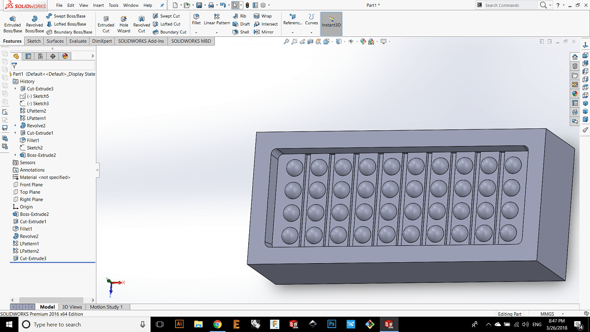
now its ready for the machining.
2.CAM
I decided to make the cam by fusion 360, and the raw material was wax and the machine that I usd is tormach pcnc 1100. After I chose the cam feature in fusion the first thing to do is to choose setup in order to make the stock dimenson and the zero point for X and Y axis, in my case I put the X and Y zeros on the top left of the stock by using the edge finderand this is because the fixed jaw of the work piece holder is the upper one.
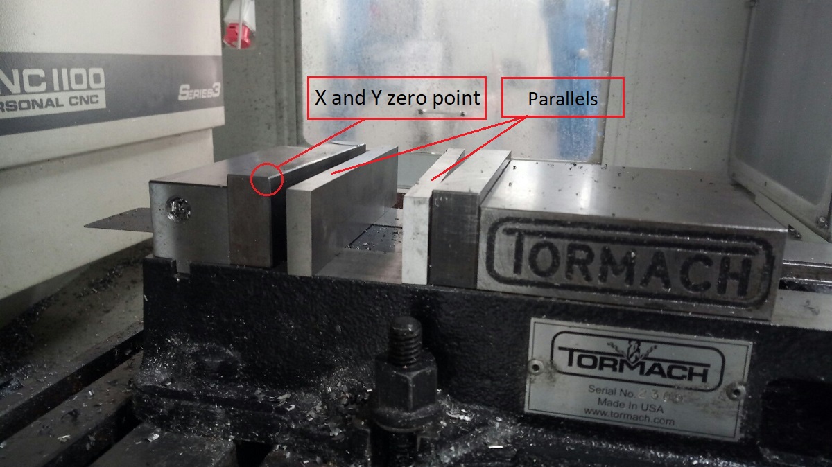

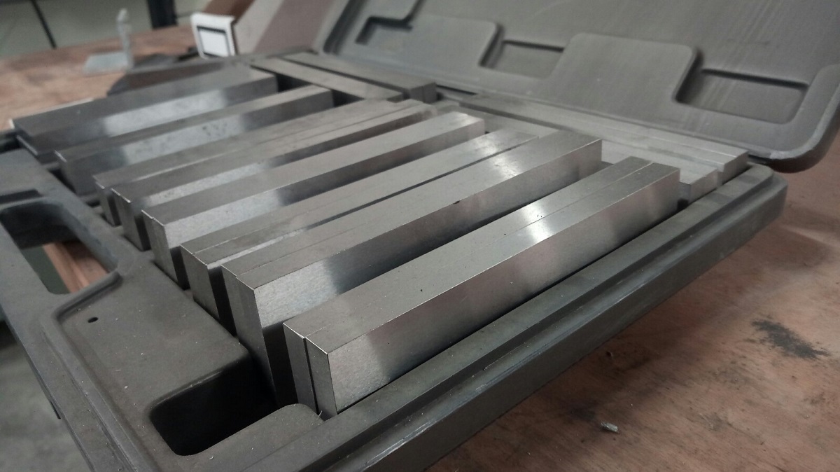
This is parallels and they are used to set the work piece at many hights as you want, and they are very acurate.
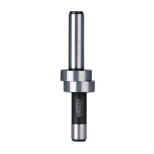
And this is the edge finder and its used to fined the edge of X and Y axis, to use the edge finder you have to set the spindle speed at low RPM because the edge finder is two separate pieces connected to each other by a spring so if you set the RPM for example 4000 rpm then the spring will not be able to connect the two pieces then the lower piece will fly, in my case I set the spindle speed at 500 RPM by typing M03 S500 on the pathpilot software which is the interface program for the tormach and what does the M03 mean is a command to make a CW rotation and S500 its mean set the spindle speed at 500.
After I set the zero X and Y and I put the wax on the parallels I made surfacing to the wax by using fly cutter.
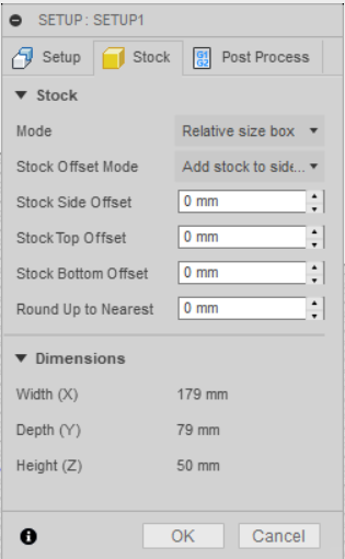
Now I went to stock and I chose relative size box and thats mean you will get a stok as the same as your model and then you determine if you want the stock to be bigger or smaller than the model, so if you want to make the stock bigger than the model by 2 mm you choose stock side offset 5mm and this is the same for stock top and stock button, but in my case I said I had made the model size as the same as the stock from beginning.
Now I want to mill the wax so I chose the first operation to be 3D pocket, for wax milling we need high RPM because the relation between the hardness and the RPM is invers relation for example if we want to mill a wood we set the RPM 18000 but if we want to mill cast iron or mild steel which they have high hardness we set the spindle speed at 900 rbm for 10mm solid carbide end mill so there is a bid diffrence between them.
Its important to say that my machine hase a maximum RPM of 5000 :(( so I used 5000 RPM and the feed rate 1500mm/min as shown, and the coolant off because its not mettal.
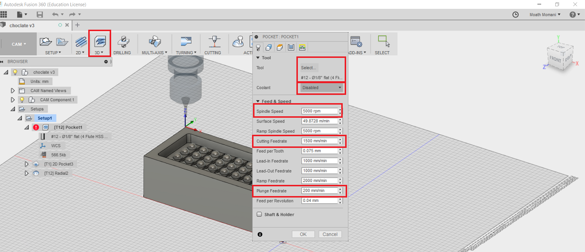
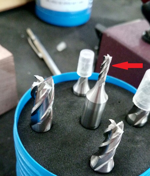
And this is the 4 flutes end mill HSS 1/8" that I used.
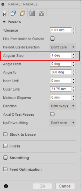
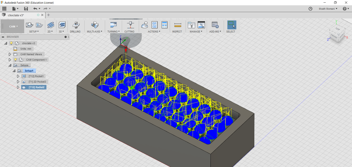
The second operation is radial fron 3D menue in order to make finishing for the spheres so I set the following cutting variables as shown in the next picture, generally in finishing we use a higher RPM but 5000 is the max limit :((
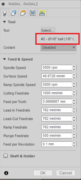
Notice for the radial operation I used ball nose 1/8" end mill because it used for finishing specially for curved surfaces.
Now from geometry I selected the models I want to mill
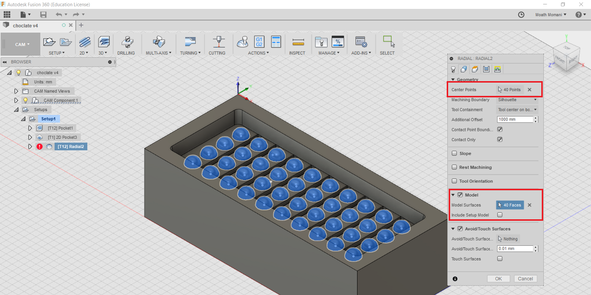
Then I set the radial offset (angular step) between each pass by 1 degree in order to get a better surface finish.
And this is the generated tool path for the radial operation.
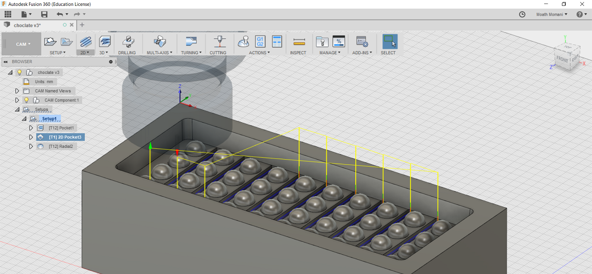
Now the last operation is a 2d pocket to make the slots so I changed the end mill to 2mm diameted solid carbide end mill so I reuced the feed rate to 500mm/m and the RPM did not changed beacause I set it at maximum.
3.MOLDING
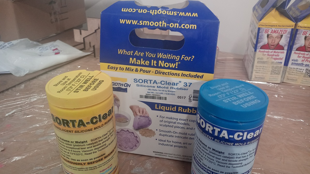
I used sorta clear to make a die for choclate so this material generally used for food.
I filled two cups with equal volume.
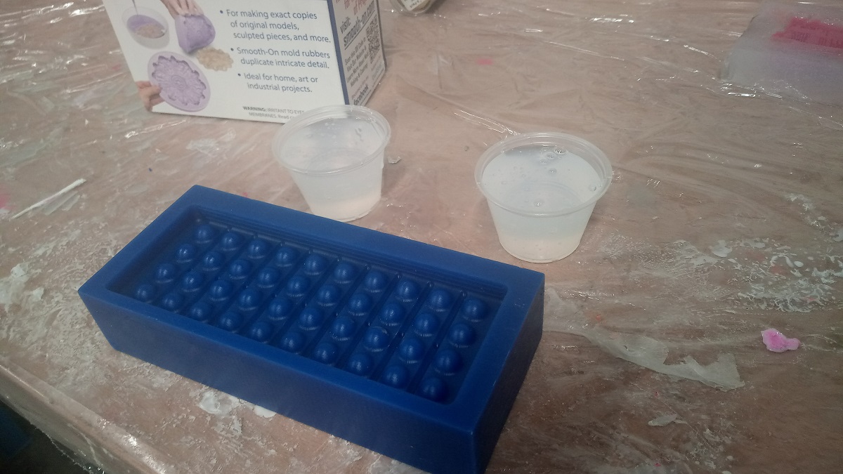
I mixed them well to make the mixture homogeneous.
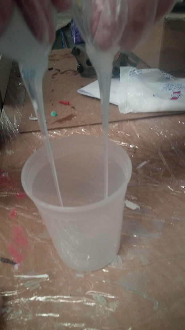
4.Problem!
After I mixd the sorta clear alot of bubbles have genarated inside of the mixture so because of that the final chocolate mold will contain alot of bubbles holes on its surfase so I need to remove the bubbles in order to get a good surface finish and how I removed the bubbles by making a vacuum space and put the mixture inside the space so the bubbles will become bigger and then it will move out the mixture and the the sphere surface will have no bibbles inside.
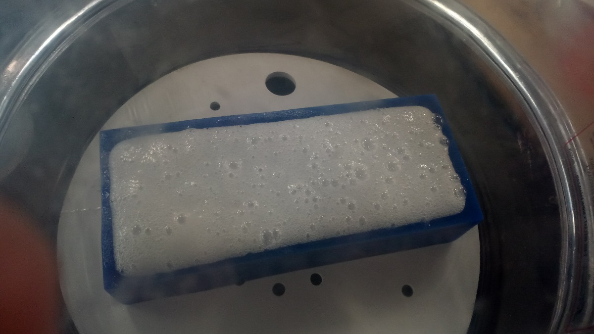
And this is how I used the vacuum pump to remove the bubbles.
This is how the bubbles go out of the mixture.
See here the spheres suface has no bubbles :D all the bubbles went to the other surface.
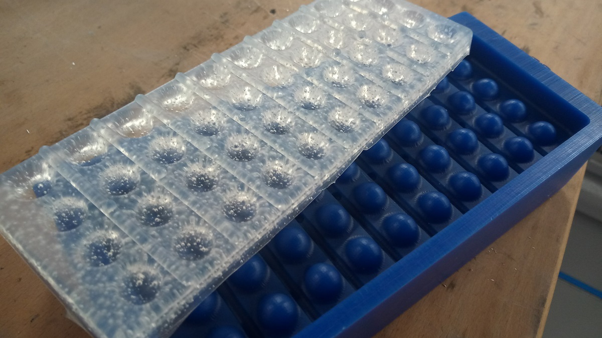
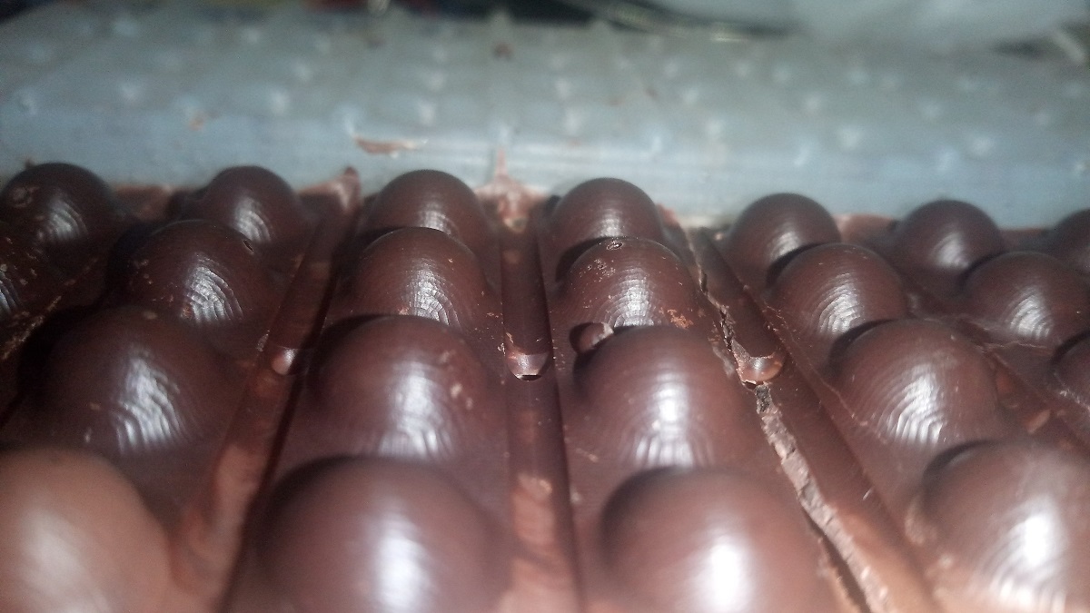
And this is my final product :))
you can download my chocolate design HERE