Introduction
In this week I am going to use two methodes of programming, the first one is by using Processing to make interface program for a dc motor and the second one by Python to plot graph of serial data from the board analog input for potentiometer.
1.CAD and CAM
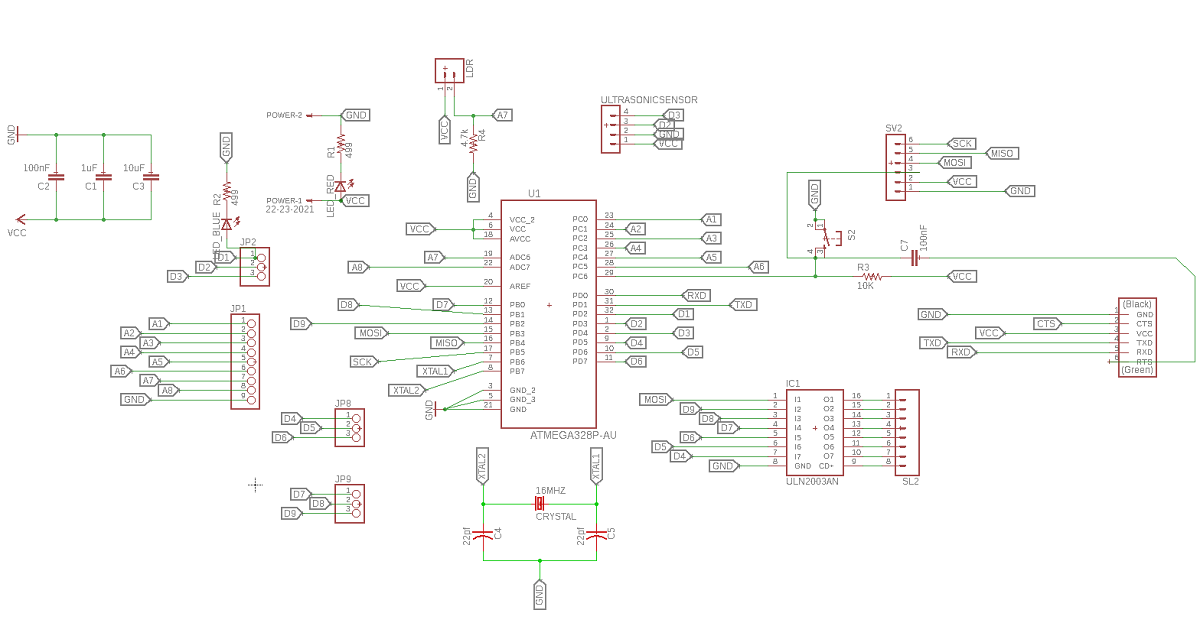
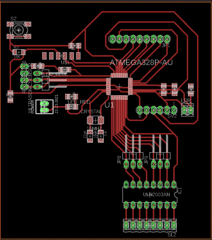
Using autodesk Eagle I designed a board with Atmega 328 and I added 4 pins for ultrasonic sensor which are the VCC, GND and pins 3 and 4 in atmega 328 pins out also I added LDR sensor connected with AD6 also I integrated my board with ULN2003AN and here is the schematic and board designs:
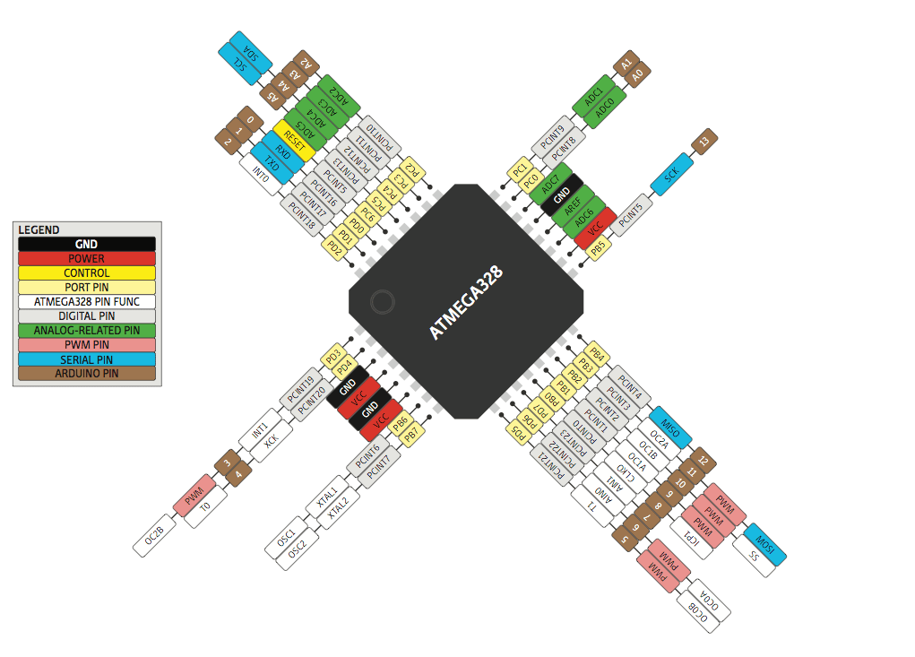
and this is Atmega 328ap pins out
After I designed my board I used the cam processor FLAT CAM
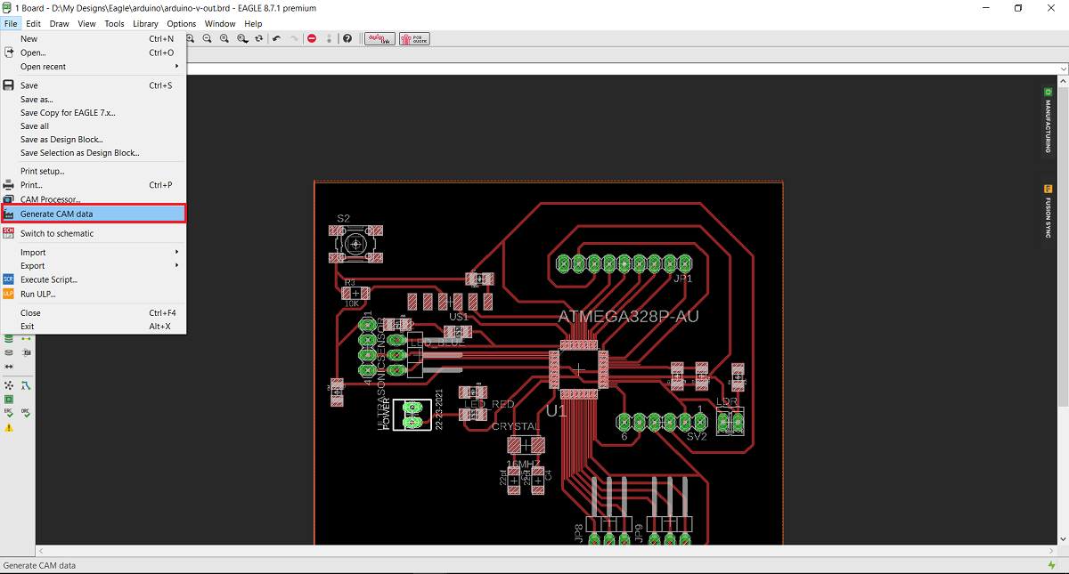
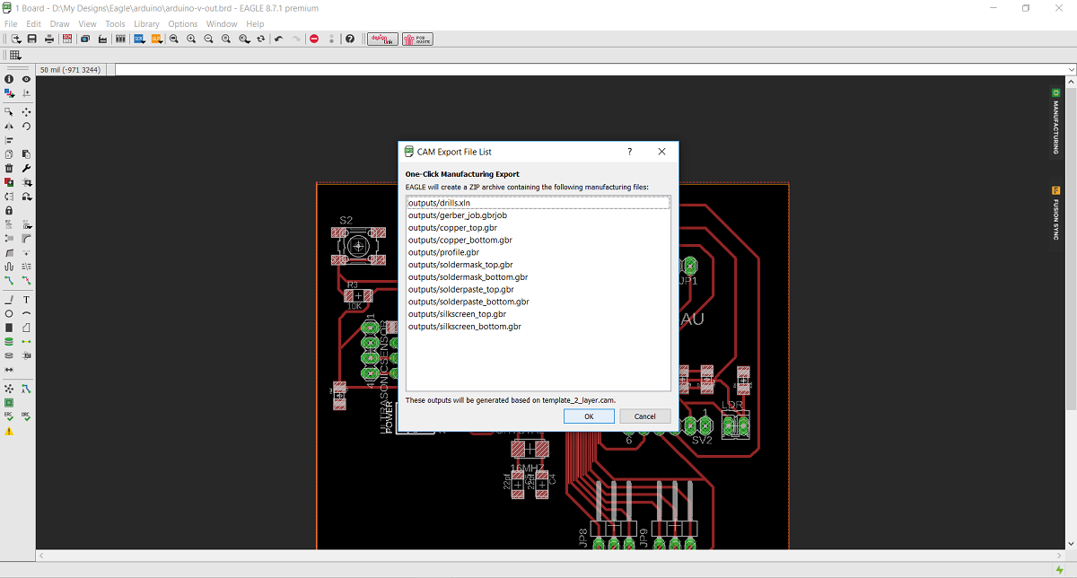
In order to use flat cam I have to get the cam files from eagle - Board layout - file - generate cam date
And this is the Gerber and Eexellon files that I will get in a zip file .
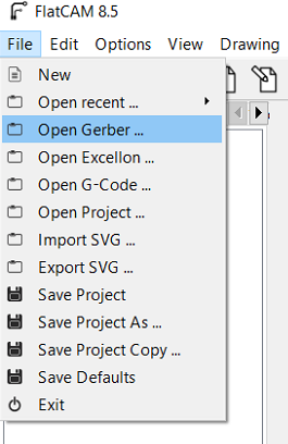
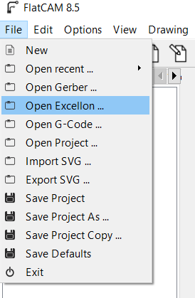
After I extracted the zip file I opened flat cam, from file I chose open gerber file wich mean I opened the file that contain the traces and the board ouside cut, then I chose open Exellon file which mean I Opened the file that contain the holes that I want to drill.
The first thing I did Is to open flat cam software then from file menue I chose open Gerber
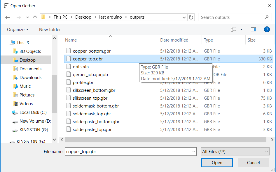
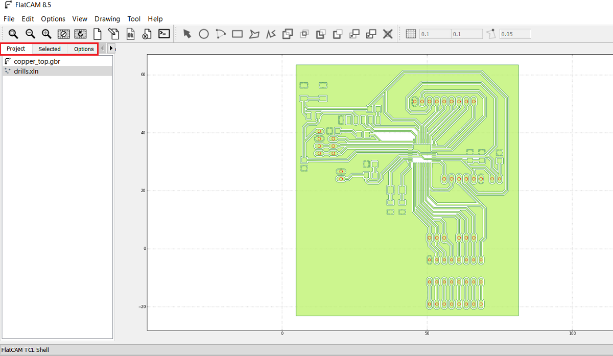
Then I selected cupper top in order to make the tool path for inside cut for the traces by 0.2 solid carbide end mill and the outside cut by 0.79 flat endmill
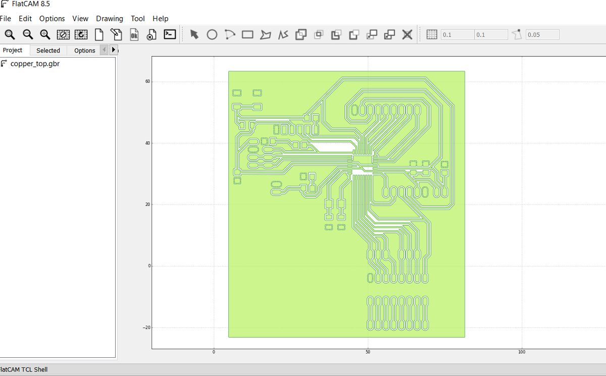
After I opened the selected file this is how its look like
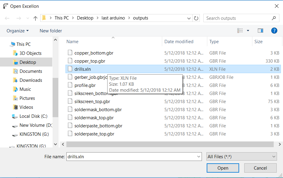
The second step is to open the Exellon file
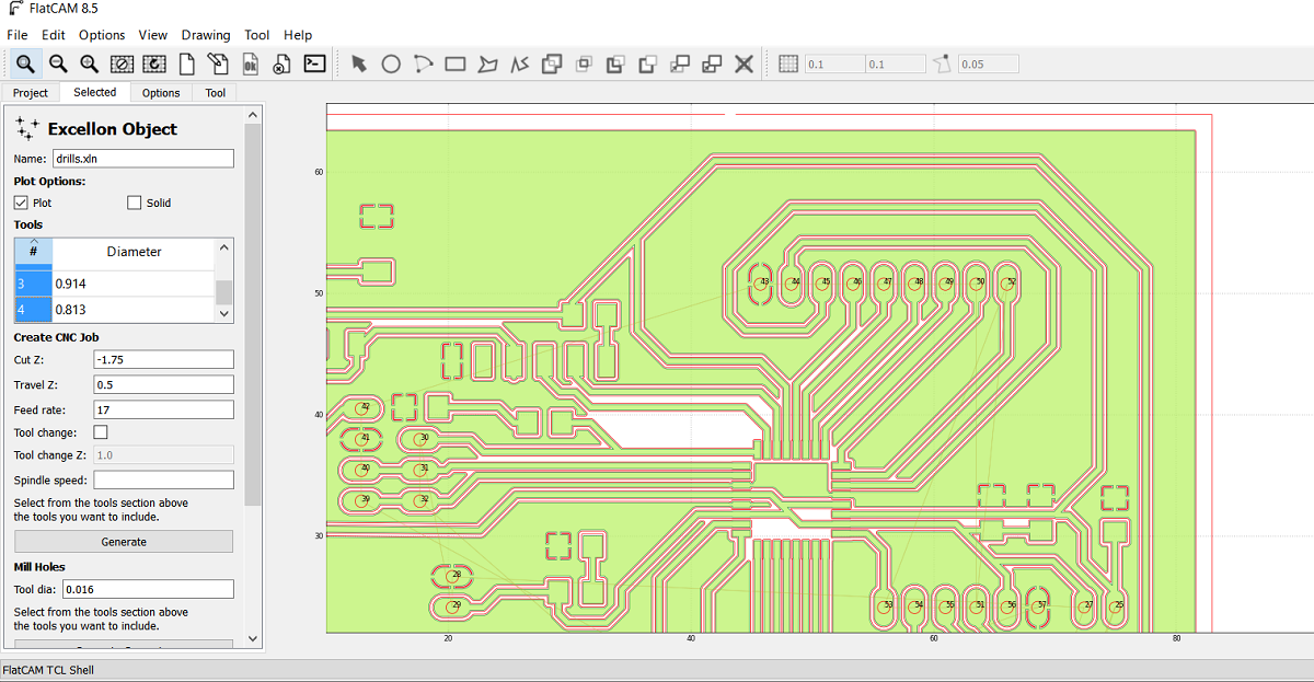
And this is the Exellon file shown as drill.xln
After I opened the Exelon file this is the red lines as shown for the holes
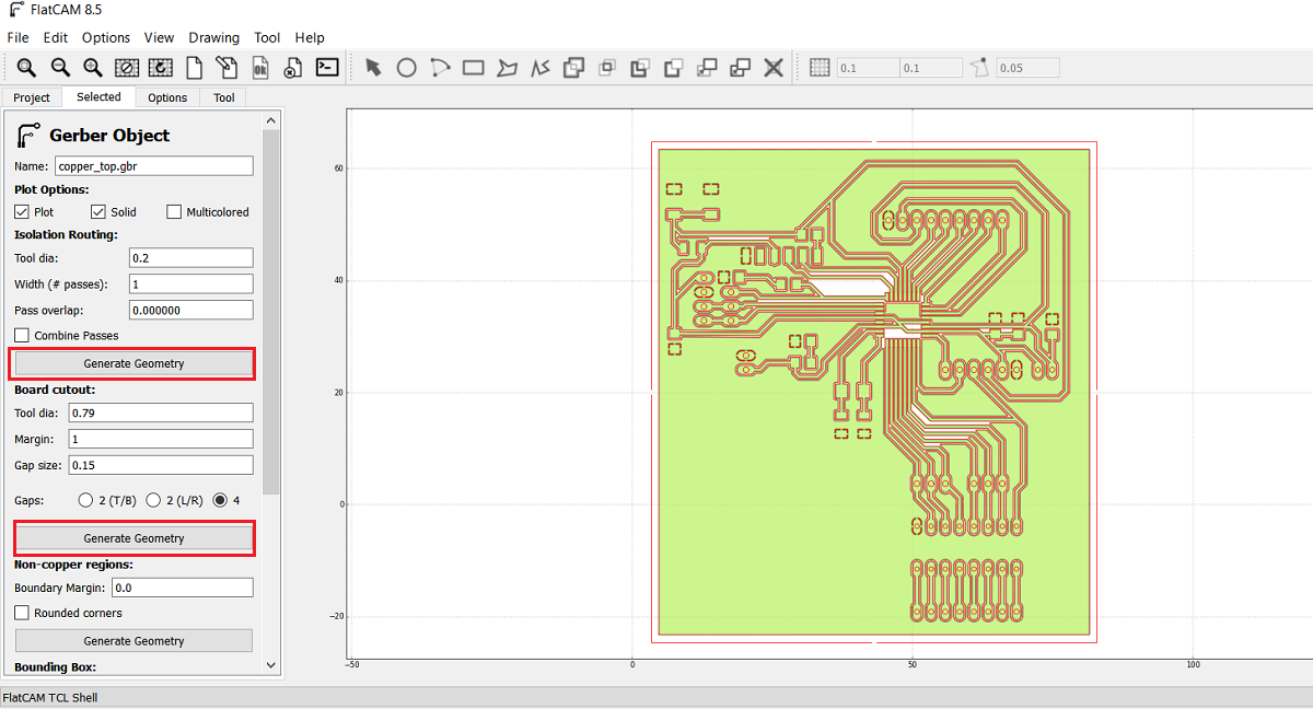
As shown in the above picture I got two jobs the first is for the inside and outside cut and the second one is for the drilling so I selected the cupper-top.gbr and then I went from project menue to select menue which in I can select the cutting variables, here I select the tool diameter of 0.2mm and the number of passes of 1 and the overlap is zero then i pressed generate geometry after this you can see the generated path for the inside cut and I did the same for board cut out and I generated the geometry as shown
Now after I finished cupper-top I went to project menue and I selected drill.xln so the main reason that forced me to learn and use flat cam instade of fabmodules is the drilling part as shown here I select all the holes diameters in this job so the 0.79 mm endmill will make all the holes but in fabmodules you have to make all the holes by black color in paint and then you can open the picture in fabmodule so using flat cam im more easy and professional
Here I put the cutting variables as shown
Now after I generated the insde, outside and drills files I got the CNC files so I opend each file.
In order to set the spendle speed I type s5000 in the exported G code this is mean the RPM is 5000 and its the maximum spindle speed in tormach PCNC 1100 and then I exported the G code as .nc
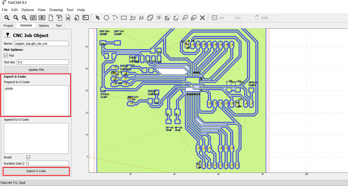
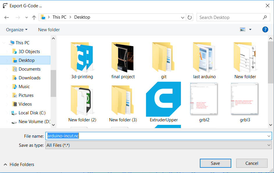
I repeated the process for the out and drill cnc files.
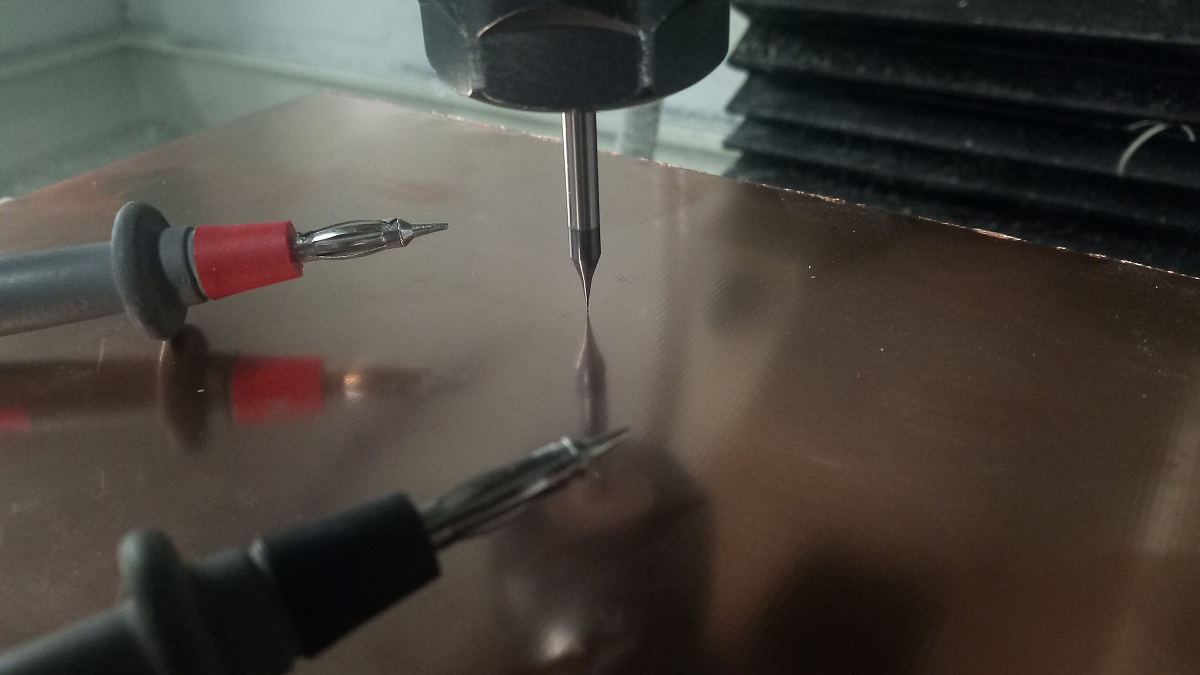
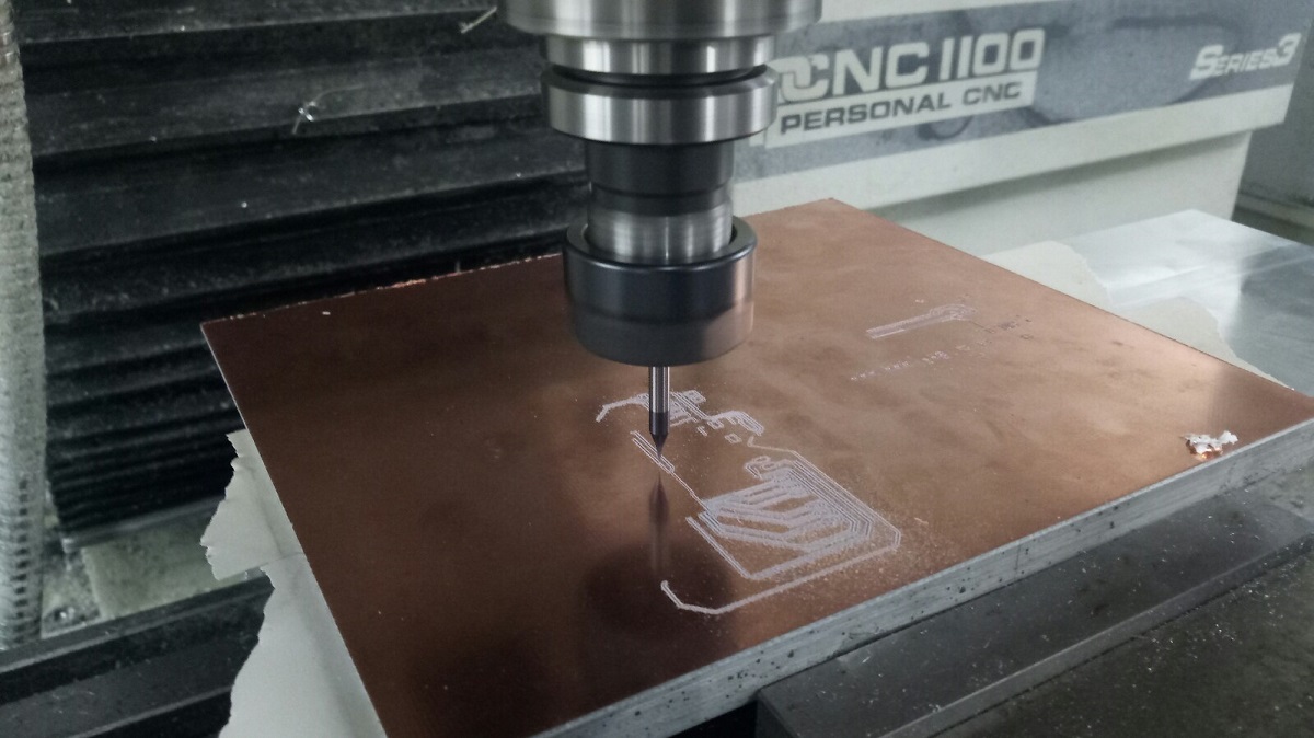
After I got the nc files I put then in a usb and the machine that I used is Tormach pcnc 1100 then I opened the file as shown
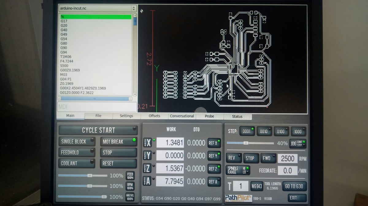
I used the Avometer to zero the z axis and thin I started the milling
And this is my board after soldering :D
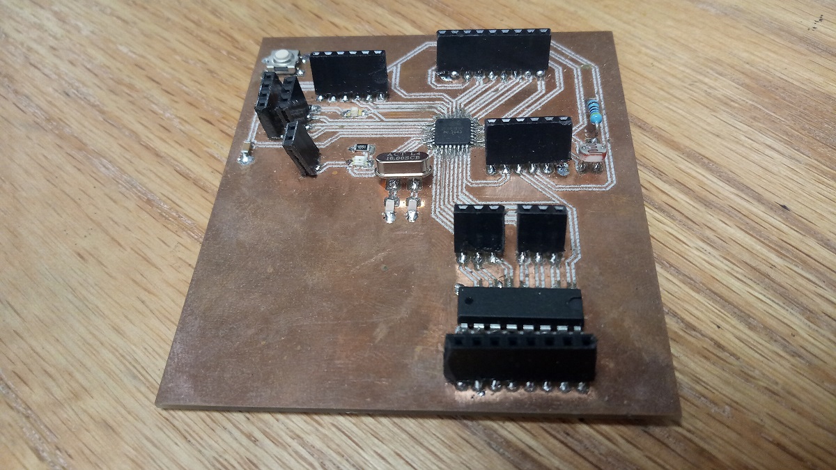
And this is the components that I used :
1.Atmega 328p is the IC.
2.Two capacitors 100nf.
3.LDR sensor.
3.Crystal 16MHz
4.Two capacitors 22pf
5.One capactor 10nf
6.One capacitor 1nf
7.Two resistors 499 ohm
8.One resistor 10k ohm
9.One resistor 4.7k ohm
10.Pin headers
11.RST buton
12.ULN 2003AN
2.programing
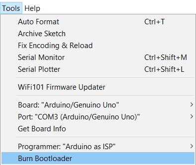
After sodering in order mo make my board programable with FTDI cable or TTL cable I have to burn bootloader and after upload a code directly using the TTL cable so to program it I used Arduino IDE, in the tools menu I selected select the right board (Arduino Uno/Genuino) and the right port after that from examples I chose Arduino ISP and I uploaded the code to arduino after I connected the board with Arduino via
RST: with Arduino Pin 10
MOSI: Master Output Slave Input with Arduino Pin 11
MISO: Master Input Slave Output with Arduino Pin 12
SCLK: Serial Clock (output from master) with Arduino Pin 13
VCC: Positive supply voltage with Arduino VCC
GND: Ground with Arduino GND
2.Processing
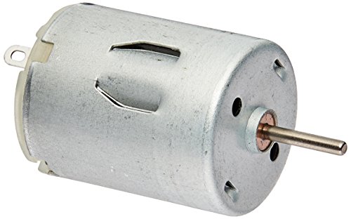
I want to make 3 buttons interface of a dc motor the firs button for CW rotation and the second button for CCW rotation and the last button is to make the motor off.
the first thing that I did is installing processing software to make the interface program.
Now I start working in arduino IDE to make the program and this is the code.
int Right = 2;
int Left = 3; // define two digital pins
char PinState;
void setup() {
  // put your setup code here, to run once:
pinMode(Right,OUTPUT);
pinMode(Left,OUTPUT);
Serial.begin(9600);

}

void loop() {
  // put your main code here, to run repeatedly:
  if(Serial.available() > 0) //if some date is avaliabe in serial port
   PinState = Serial.read(); //read the vaule

  if(PinState == '1'){ //if statement will be 1
    digitalWrite(Right,HIGH);
    digitalWrite(Left,LOW);

  }
if(PinState == '0'){ //if statement will be  0
digitalWrite(Right,LOW);
digitalWrite(Left,HIGH);

}
if(PinState == '2'){ //if statement will be 2
digitalWrite(Right,LOW);
digitalWrite(Left,LOW);
}
}
After that I start using processing to make the interface program
It is look like arduino so much but diffrent codes
This is the code that I used to make the first interface program,
import processing.serial.*; //import the library for serial communication
Serial myPort;               //define name of the serial communication
PImage bg;
void setup(){
  size(500,312); //set the image size
  bg=loadImage ("dc-motor.jpg");
  myPort=new Serial(this, "COM3",9600); //arduino COM port
}


void draw(){
background(bg);
if(mousePressed && (mouseButton== LEFT)){
  myPort.write('0');
}
if(mousePressed && (mouseButton == RIGHT)){
  myPort.write('1');
}

}
When you run the program if you clicked right mouse button them the motor rotate and if you clicked lefft mouse button the rotation will reflict
This is a video for the first code
Now lets start with the second code, the interface contain three buttons
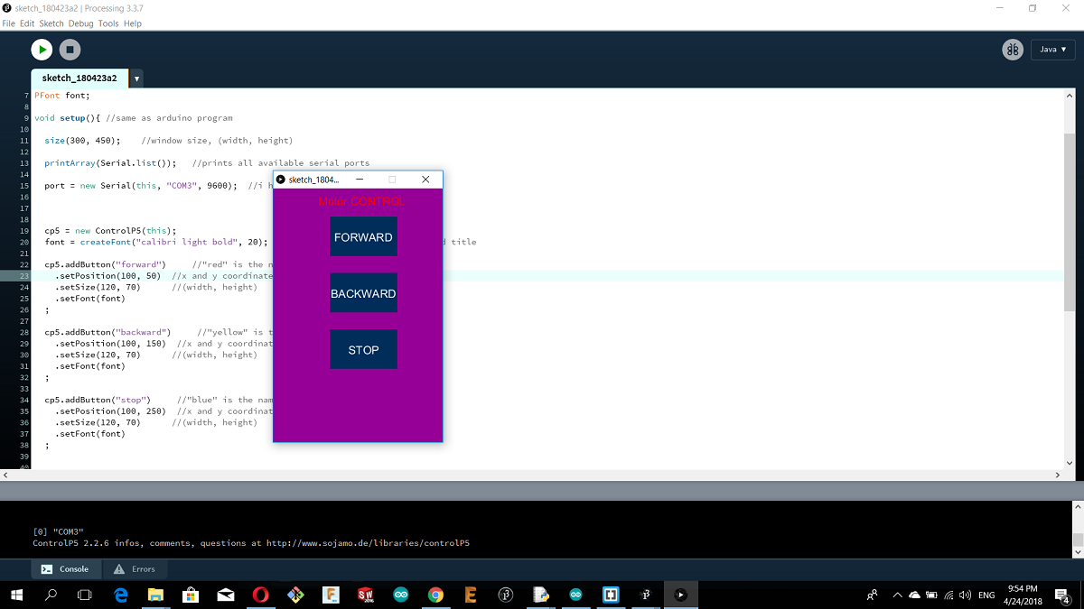
As shown in the picture there is 3 buttons for CW rotation and the 2nd one for CCW rotation and the 3ed one is off button
And here is the processing code
import controlP5.*; //import ControlP5 library
import processing.serial.*;

Serial port;

ControlP5 cp5; //create ControlP5 object
PFont font;

void setup(){ //same as arduino program

  size(300, 450);    //window size, (width, height)

  printArray(Serial.list());   //prints all available serial ports

  port = new Serial(this, "COM3", 9600);  //i have connected arduino to com3


  cp5 = new ControlP5(this);
  font = createFont("calibri light bold", 20);    // custom fonts for buttons and title

  cp5.addButton("forward")
    .setPosition(100, 50)
    .setSize(120, 70)
    .setFont(font)
  ;

  cp5.addButton("backward")
    .setPosition(100, 150)
    .setSize(120, 70)
    .setFont(font)
  ;

  cp5.addButton("stop")
    .setPosition(100, 250)
    .setSize(120, 70)      //(width, height)
    .setFont(font)
  ;


}

void draw(){  //same as loop in arduino

  background(150, 0 , 150); // background color of window (r, g, b) or (0 to 255)

  //lets give title to our window
  fill(255, 0, 0);               //text color (r, g, b)
  textFont(font);
  text("Motor CONTROL", 80, 30);  // ("text", x coordinate, y coordinat)
}

//lets add some functions to our buttons
//so whe you press any button, it sends perticular char over serial port

void forward(){
  port.write('0');
}

void backward(){
  port.write('1');
}

void stop(){
  port.write('2');
}
Here is a video :D
3.Python
Before I start programming through python,I have to demonstrate some concipts about arduino.
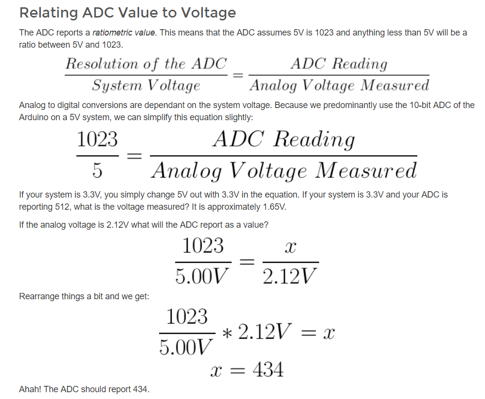
What is the ADC?
An Analog to Digital Converter (ADC) is a very useful feature that converts an analog voltage on a pin to a digital number.Not every pin on a microcontroller has the ability to do analog to digital conversions. On the Arduino board, these pins have an ‘A’ in front of their label (A0 through A5) to indicate these pins can read analog voltages.
ADCs can vary greatly between microcontroller. The ADC on the Arduino is a 10-bit ADC meaning it has the ability to detect 1,024 (2^10) discrete analog levels. Some microcontrollers have 8-bit ADCs (2^8 = 256 discrete levels) and some have 16-bit ADCs (2^16 = 65,536 discrete levels).
Honestly this is first time I use python, so I found two seriese of python software. Pythone 2 series and python 3 series I installed Python 2 series 2.7.14 for windows also I used python in ubuntu.
After I installed it I installed Vpython 2.7 VPython makes it easy to create navigable 3D displays and animations, even for those with limited programming experience. Because it is based on Python, and this is the Vpython software
After, I installed pyserial. PySerial is a Python API module to access the serial port when making a serial communication with arduino and pyserial includes the serial libraries.
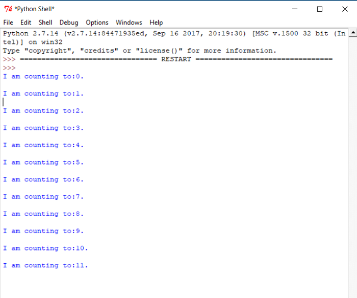
This is a simple arduino code to print the numbers from zero to infinity.
int counter=0;
void setup() {
  // put your setup code here, to run once:


Serial.begin(9600);
}

void loop() {
  // put your main code here, to run repeatedly:
Serial.print("I am counting to:");
Serial.print(counter);
Serial.println(".");
counter=counter+1;
delay(2000);
}
After, I opened Vpython to write the following code in python.
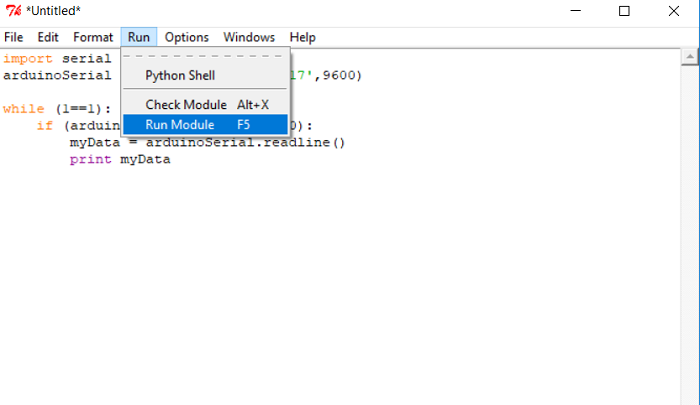
import serial    #to import the library
arduinoSerial = serial.Serial('com17',9600)    # the arduinoSerial equal the output from the arduino code in serial monitor with cosidering the same port and pound rate

while (1==1):        #in python there is no void loop as arduino so I made a loop in this way while always 1 equal 1
    if (arduinoSerial.inWaiting()>0):           #if there is data in the serial then go and notice that there is no simicolon in python
        myData = arduinoSerial.readline()       #in python we define the variable once so we dond need to define myData in void setup as arduino
        print myData
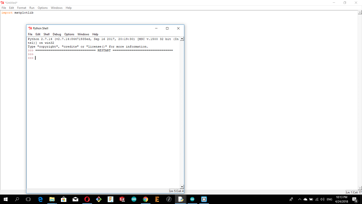
what I have to do now is just to run the module as shown.
and here is the serial monitor (python shell)
After the previous simple code I want to write an advanced code to show how to import new libraries.
What I want to write in python is a code to plot a graph of serial data from the board analog input for potentiometer so I need the arduino code then I need the python code. To run the python code on vpython I have to install some modules(libraries), So lets start with the arduino code.

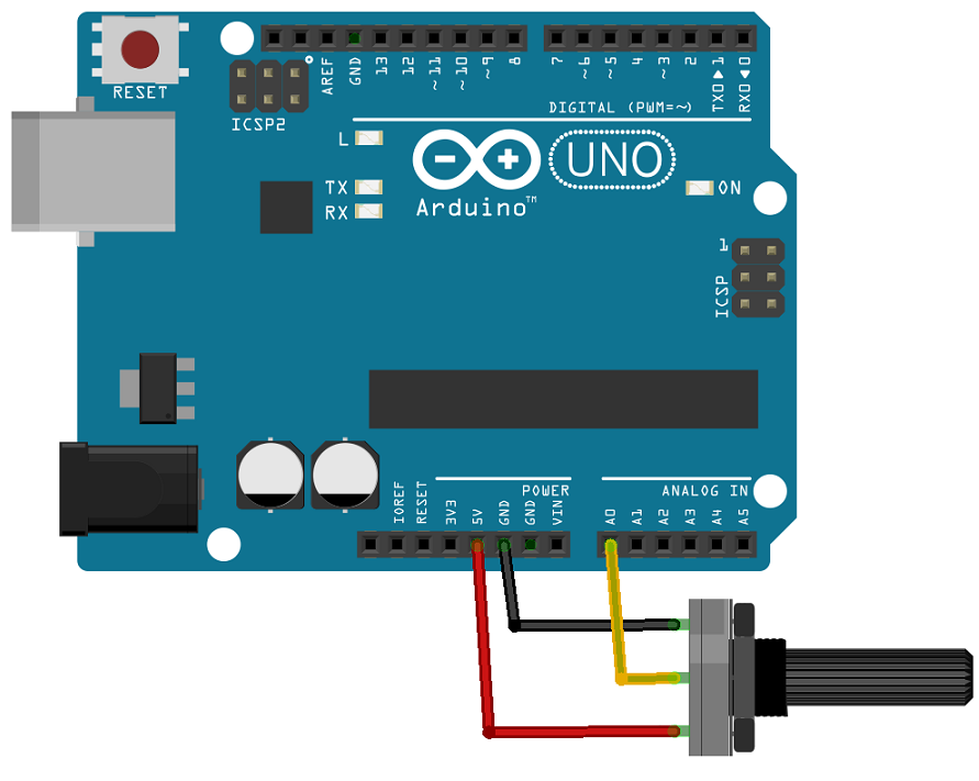
I connected the potentiometer with the breadboard as shown in the picture
And this is the Arduino code for python
const int analogIn = A0;
int analogVal = 0;

void setup() {
  Serial.begin(19200);
 }

void loop() {
  analogVal = analogRead(analogIn);
  Serial.println(analogVal);
  delay(1000);

}
Problem??
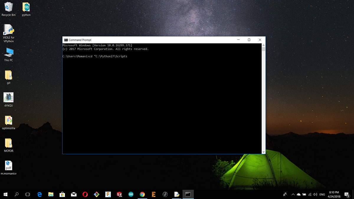
After I uploaded the code to arduino, it is the time to write the python code but first I have to install the necessary modules for the code because if I type import serial in vpython it will not recognize it so what I have to do is installing them, and this is the way how to install python modules.For my case I installed python on C drive so you just copy this link where the scrips location
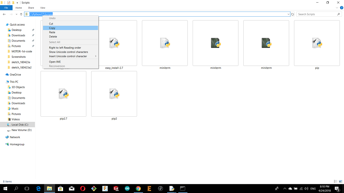
after that open the command prompt and type:
cd "(the scripts location)
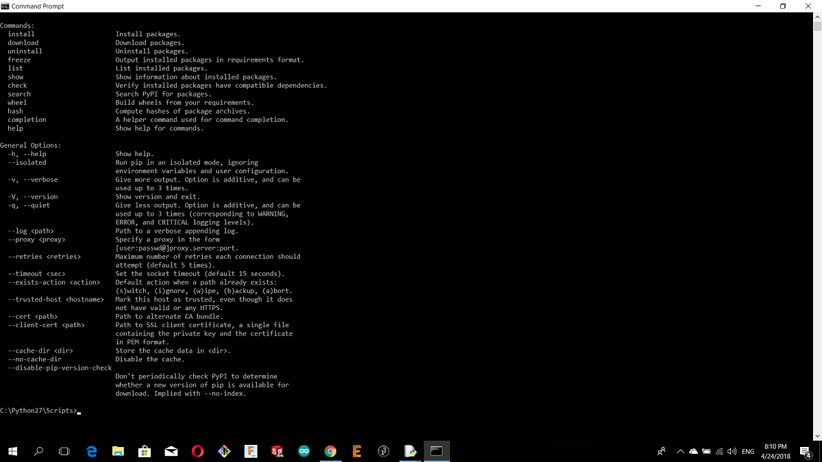
then type pip
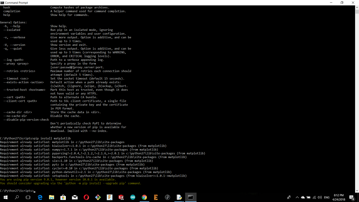
Now i want to install first matplotlib module the first so type :
pip install matplotlib
and the module will installed
then
pip install serial
then pip install drawnow
For now we installed 3 necessary modules to run my python code in vpython
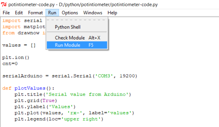
and here is my python code in vpython
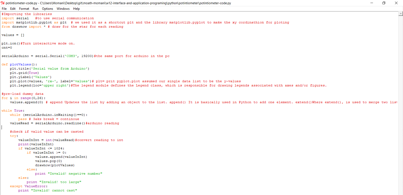
Focuse on your port
Now its the time to run the code
and this is a video
You can download my sorce files from here
For processing
1.DC MOTOR ARDUINO CODE
2.FIRST PROCESSING CODE and MOTOR PICTURE
3.SECOND PROCESSING CODE
For python
1.ARDUNO CODE FOR PYTHON
2.VPYTHON CODE FOR POTINTIOMETER