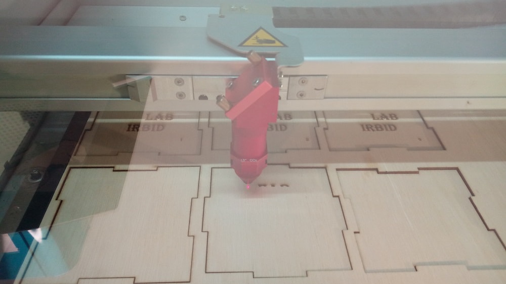
In this week I am going to use 2 machines:
1.Laser cutter.
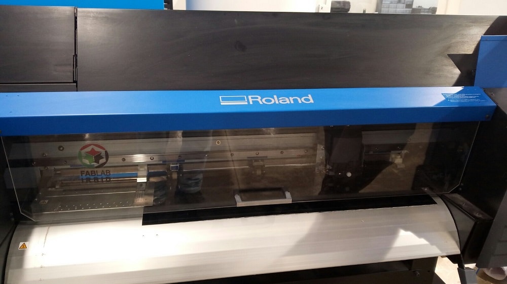
2.Roland vinyl cutter.
1.Laser cutter
Laser cutting is a technology that uses a laser to cut materials, and is typically used for industrial manufacturing applications, there are 3 types of laser used in laser cutting:
1.Gas laser cutting
Gas laser cutting machines, using C02 gas, is a commonly used form of laser cutting, but with a wavelength of 10.6 micrometres, it is only useful for non-metals.
2.Crystal laser cutting
Crystal laser cutting, is conducted using nd:YAG (neodymium-doped yttrium aluminium garnet) or nd:YVO (neodymium-doped yttrium ortho-vanadate) laser cutting machines. This process is similar to the fiber laser cutting process, and with a wavelength of 1.064 micrometres, can be used on both metals and non-metals.
3.Fiber laser cutting
Fiber laser cutting is a process where the core component used is an optical fiber, typically doped with rare elements such as erbium, thulium and dysprosium. A fiber laser cutting machine has the same wavelength of that as a crystal laser cutting machine, 1.064 micrometres, and so can work with both metals and non-metals.
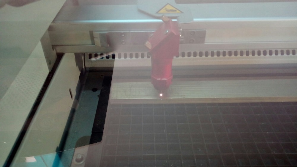
The machine that I used is trotec speedy 400 its a CO2 laser machine, the maximm power in the machine is 300 W which is relatively low comparing with the fiber and crystal laser cuttters that can reach power of 3KW.
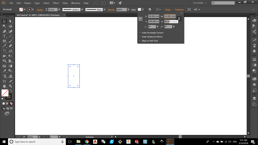
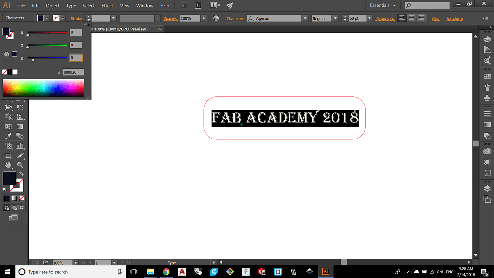
The first thing I did is the design using Illustrator to measure something called kerf, Kerf is defined as the width of material that is removed by acutting process.It was originally used to describe how much wood was removed by a saw, because the teeth on a saw are bent to the side, so that they remove more material than the width of the saw blade itself, preventing the bladefrom gettingstuck in thewood.
I chose rectangle from the tool bar
and I made many copies
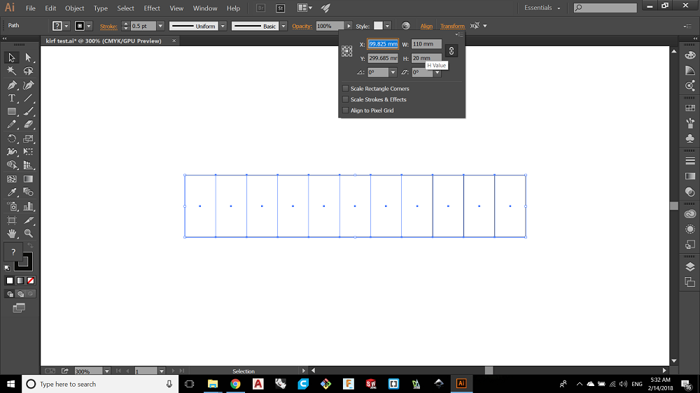
The total lenght of the all rectangles is 110mm and all the lines are not repeated on each others, every line is a single line.
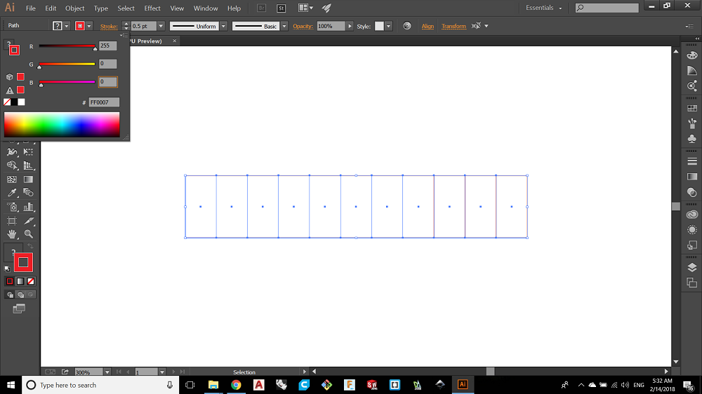
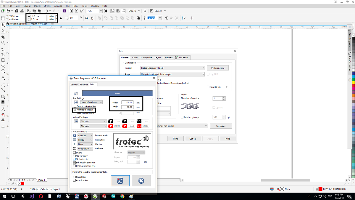
Now to make the lines defined to the laser we should conseder this points:
1. The color type is RGB.
2. For cutting the lines should be red and the line size is hairline 0.01px.
3. For engraving the color shoud be black.
Note:we can define any color we want.
After that I printed the design CTR+P.
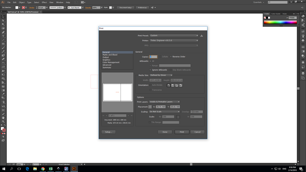
As we see the trotec laser defined as a printer.
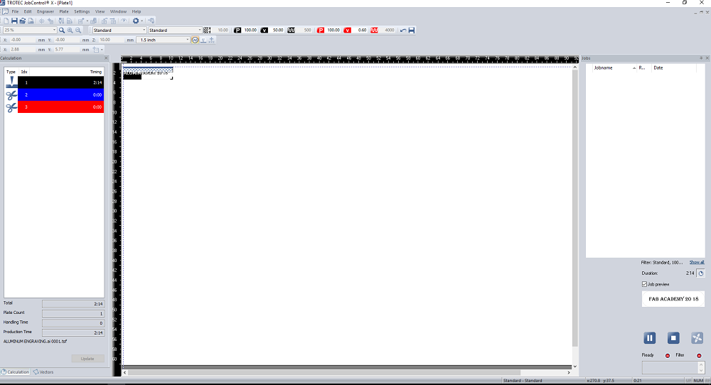
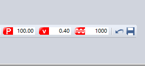
this is the interface program for the laser, we choose the cutting variables like the same in the CAM softwares.
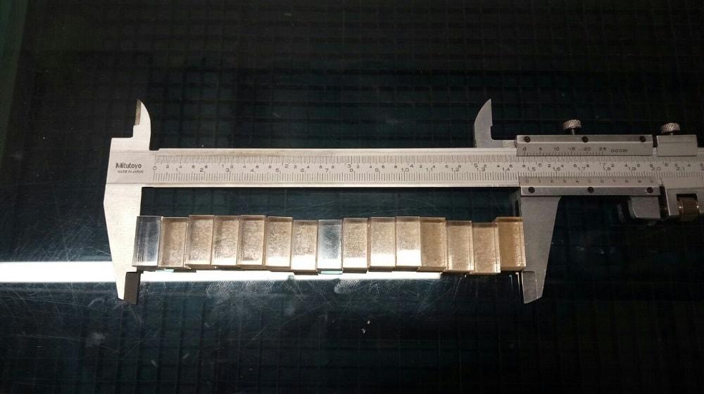
Now I am going to test the kerf for plywood of thickness 5mm.
I tried the cut 3 times for different speeds of cut.
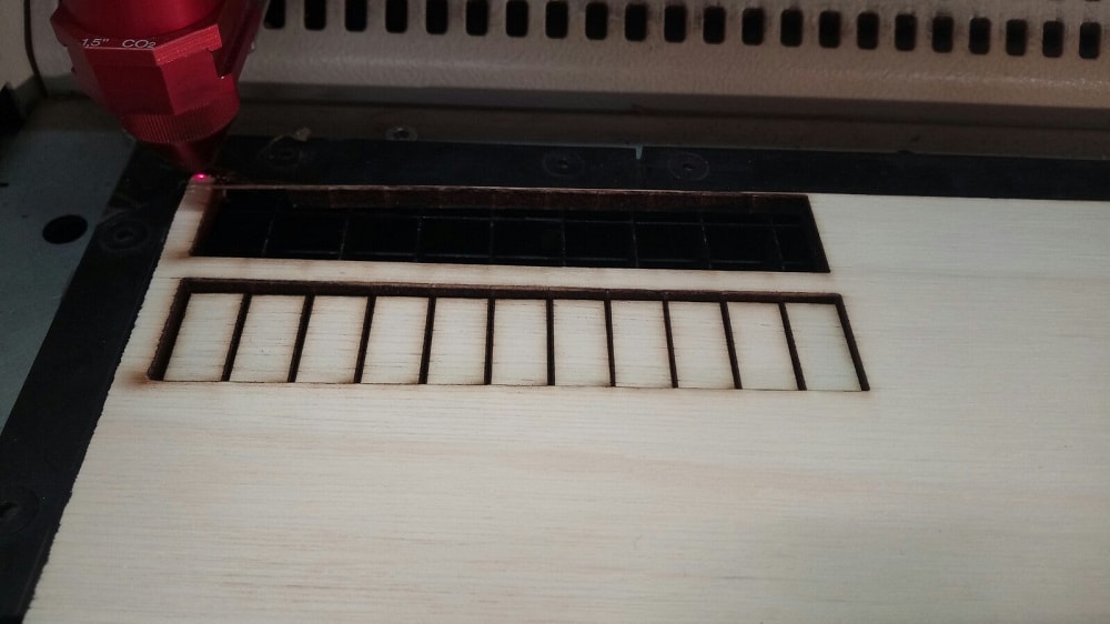
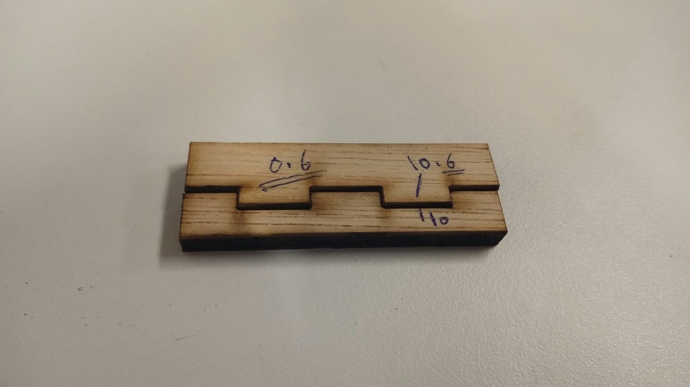
First cut
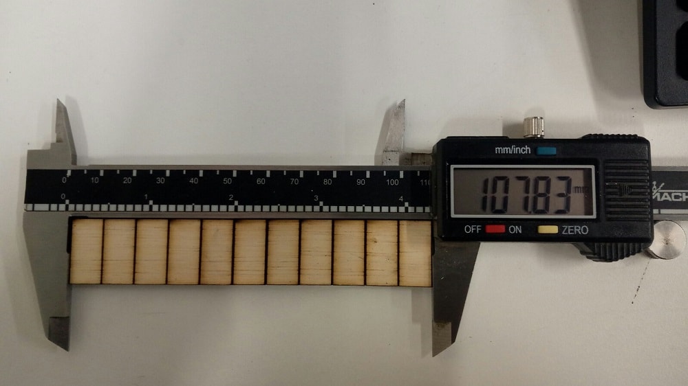
The Kerf=(110-107.83)/12 = 0.18mm
After the calculation we can see a perfect mesh.
Second cut
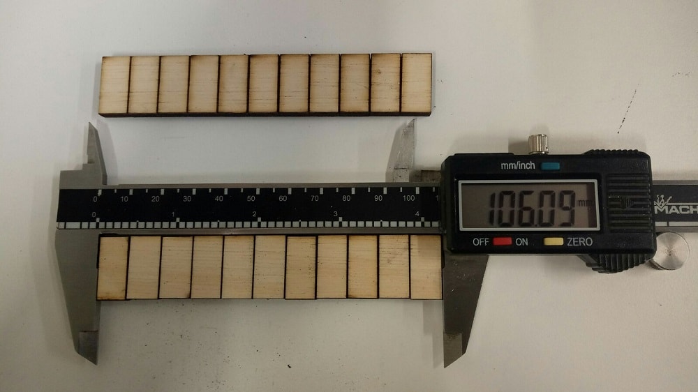
The Kerf=(110-106.09)/12 = 0.32
Third cut
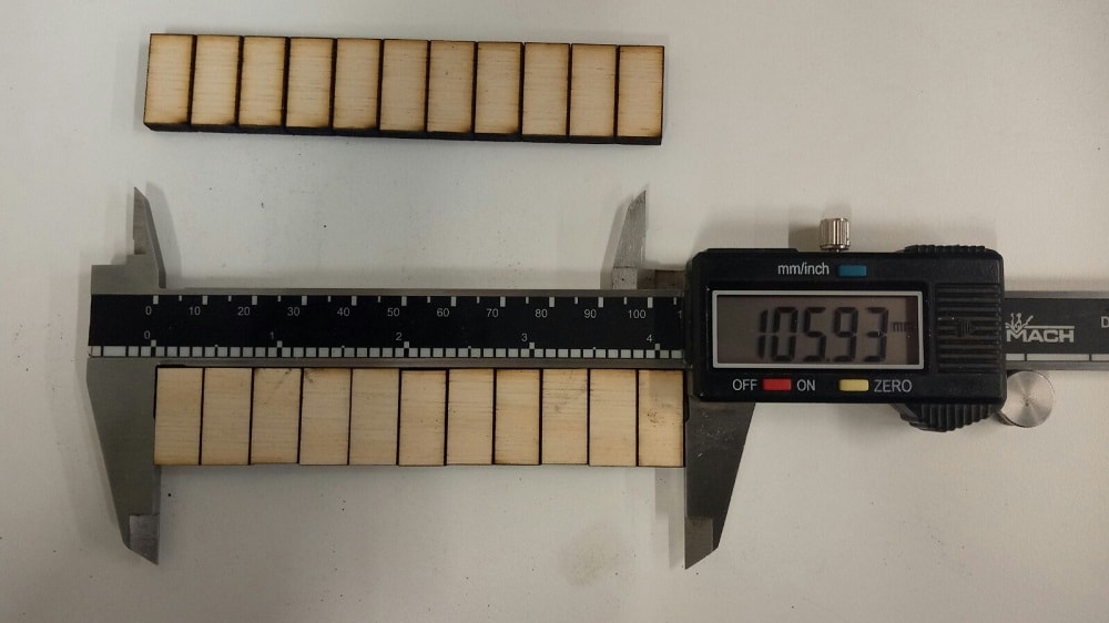
The Kerf=(110-105.93)/12 = 0.34
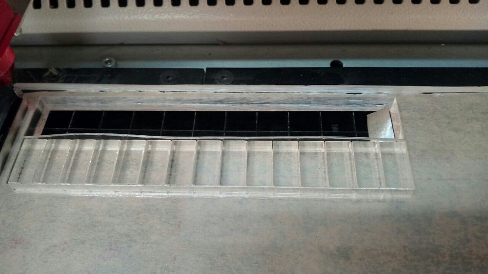
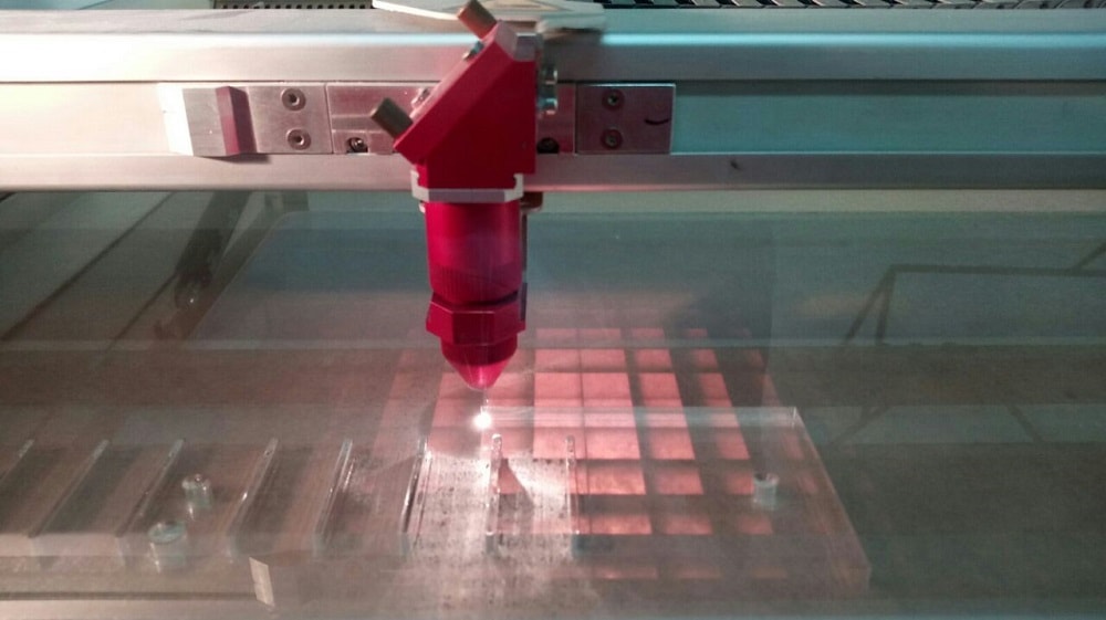
Now I am going to test the kerf for Acrylic of thickness 10mm, I tried many cutting speeds and frequencies so the the best speed to cut the 10mm of acrylic is v=0.15 p=100 hz=55k.
After that I start the design, I chose Draft sight which is a free 2d design software, to measure the kerf.
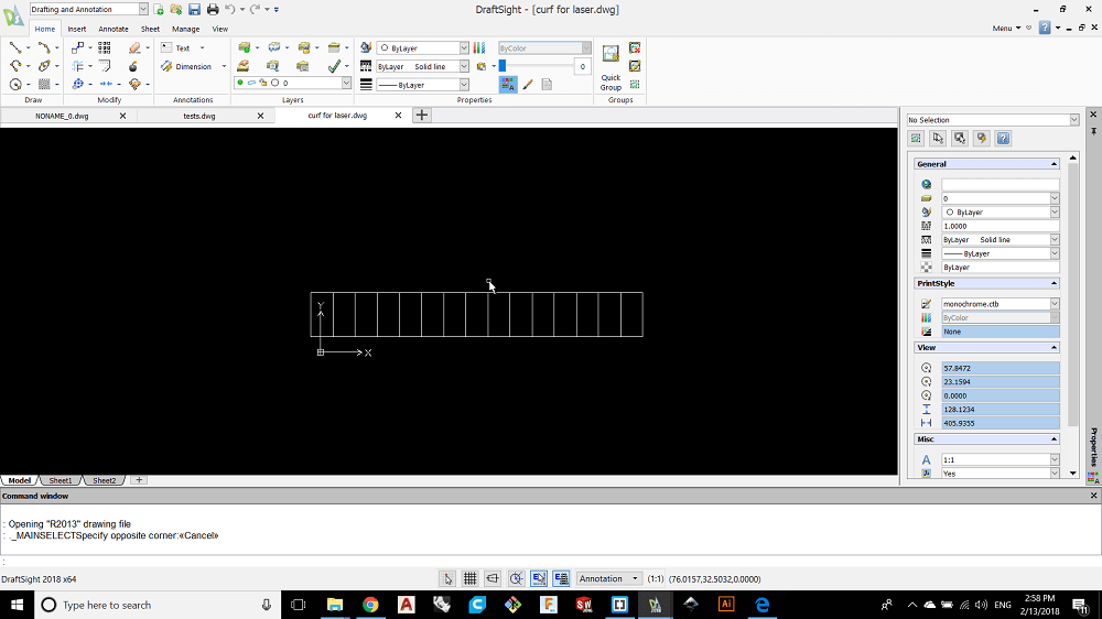
after that i measured the kerf and its equal to the real length befor cutting - acutual length after cutting devided by the number of the cut lines.
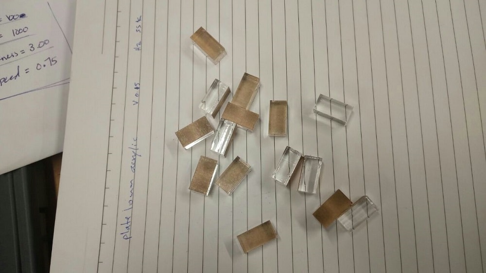
in our case the kerf =150-147.2/16= 0.175mm
I noticed that the relation between the Kerf and the cuting speed inverse relation and Kefr has a propotional relation with power.
After that I designed a box using draft sight and I used the plywood 5mm thickness.
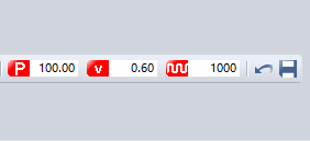
The cutting variabels that I will use are v=0.6 , p=100 and F=1000 with considering the calculated kerf of 0.18mm.
.png)
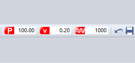
the setting that i used is v=0.6 and power=100 hz=1000 with considering the erf value.

I tried to engrave on aluminum and cupper with a very law speed of 20 and power 100%
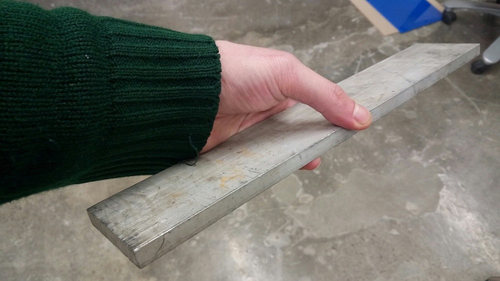
the results not good, the machine can not engrave on metals.
there is one important thing that helps to cut the materials and this thing is the focal length of the lence so if we want to cut 12mm of acrylic its better to use a lence with hifh focal length , I used 2.5" to cut this plate but if i used 1.5" lence in the same conditions you will see that the 2.5" lence is better to cut.
and the reason is the focal length of the lence.
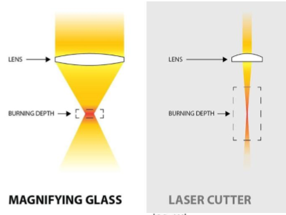
BUT for Engraving the 1.5" lence is better.
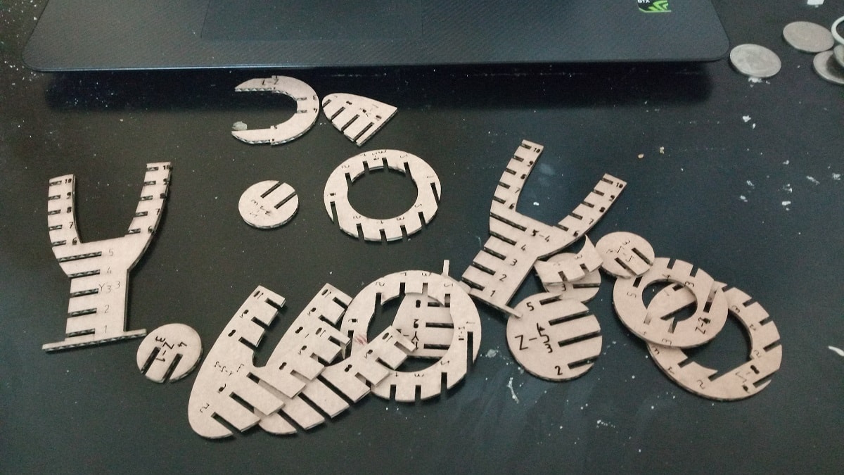
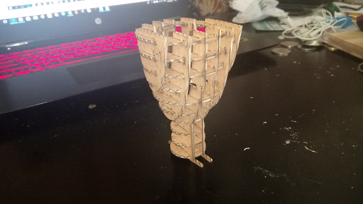
Now I'm going to make a 3D model from 2D cut by creating a 3D model and slice it in fusion 360 slicer and im going to use cardboard 2mm thickness in this process so the first thing is to calculate the kerf for the cardboard
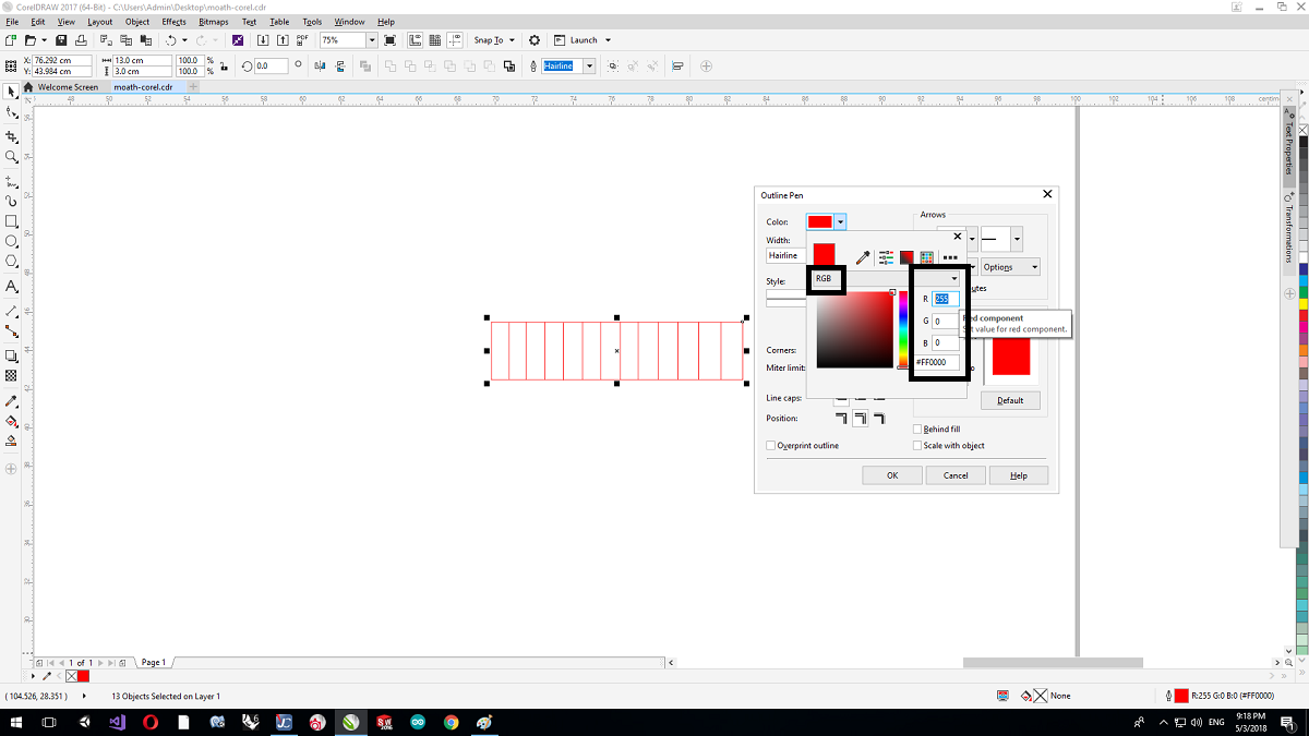
I started the design by using Corel Draw software so I made the design and the most important thing is to make the color type is RGB for red 255,0,0
then I printed the job
I used two cuts to measure the kerf
1. P=100 V=2.5 Hz=200

2. P=100 V=3 Hz=200

And this is the kerf
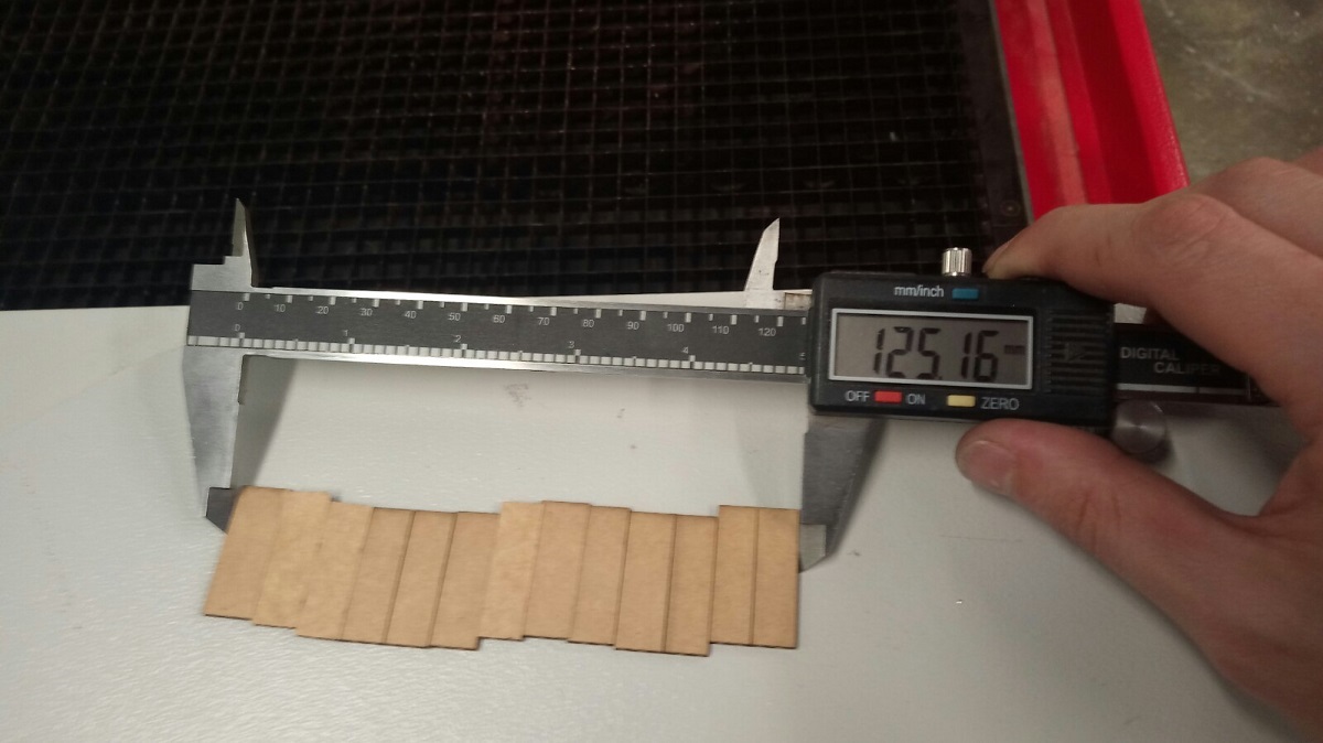
(130-125,2)/14 = 0.3
I designed the model using fusion, I chose sclupt and I made a sphere
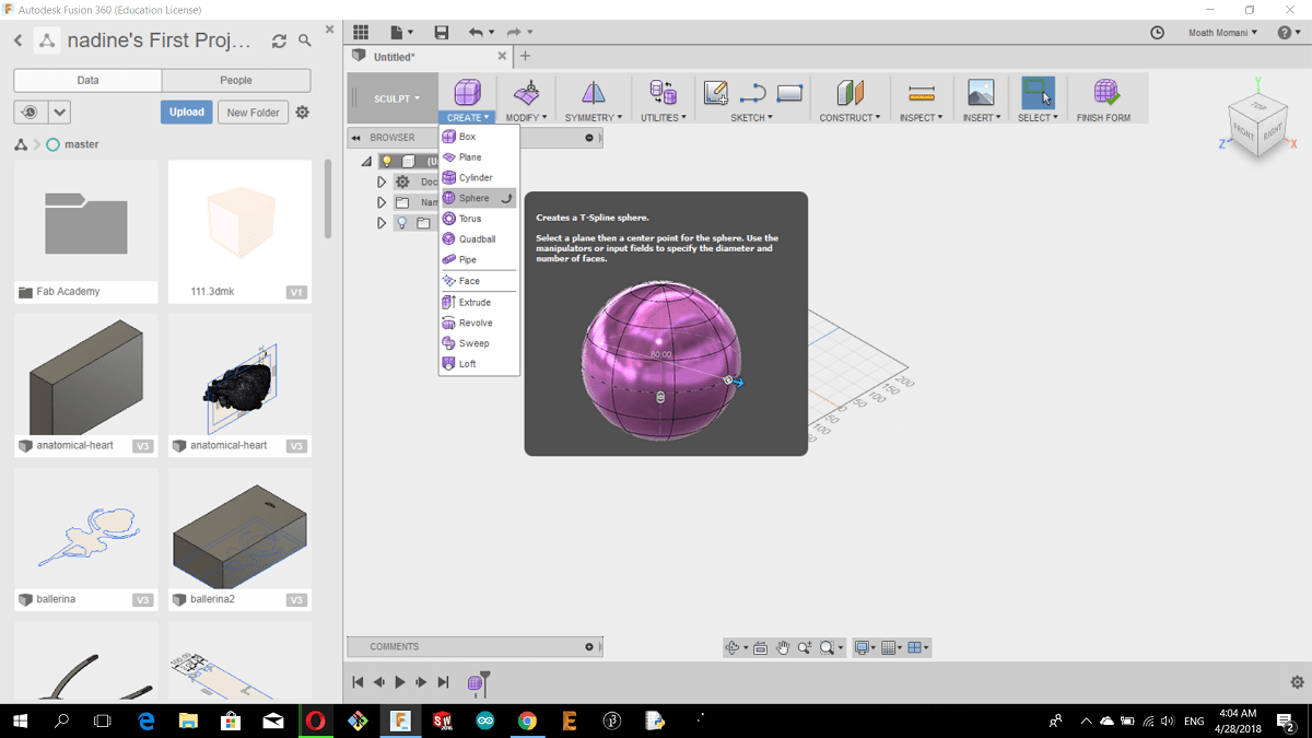
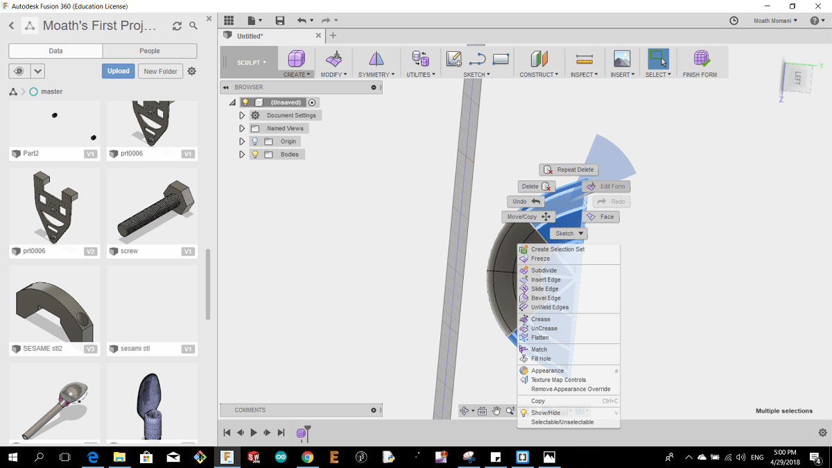
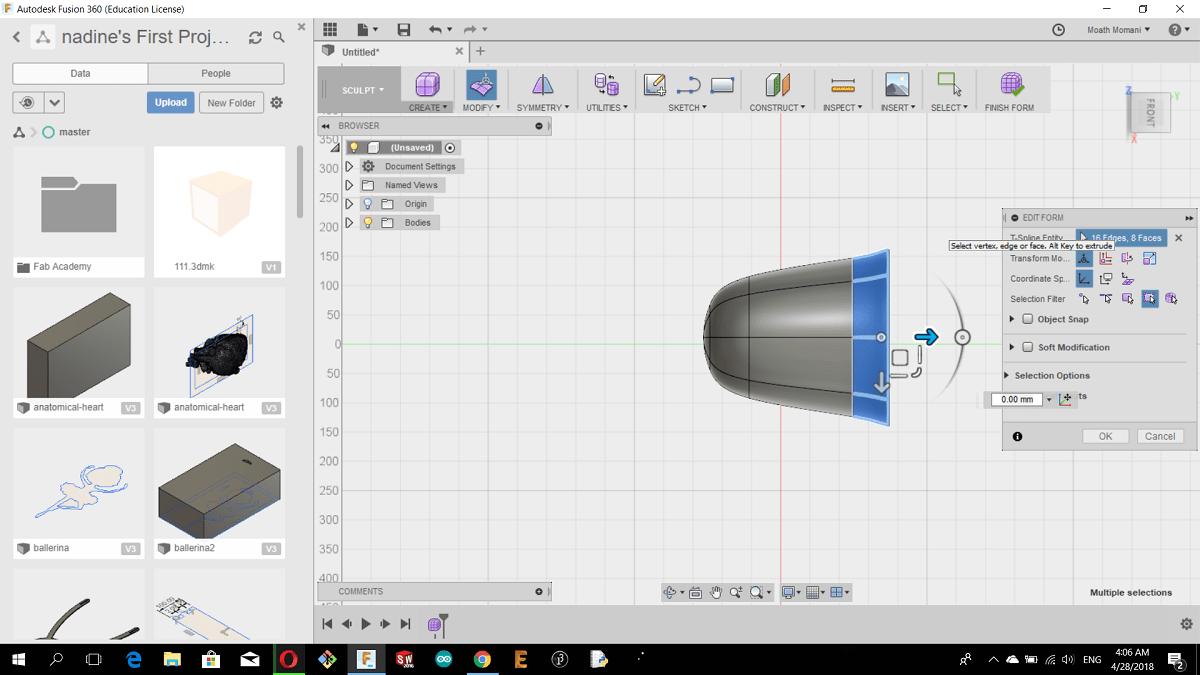
then right I selected the half of the sphere and deleted it, then right click and edit form
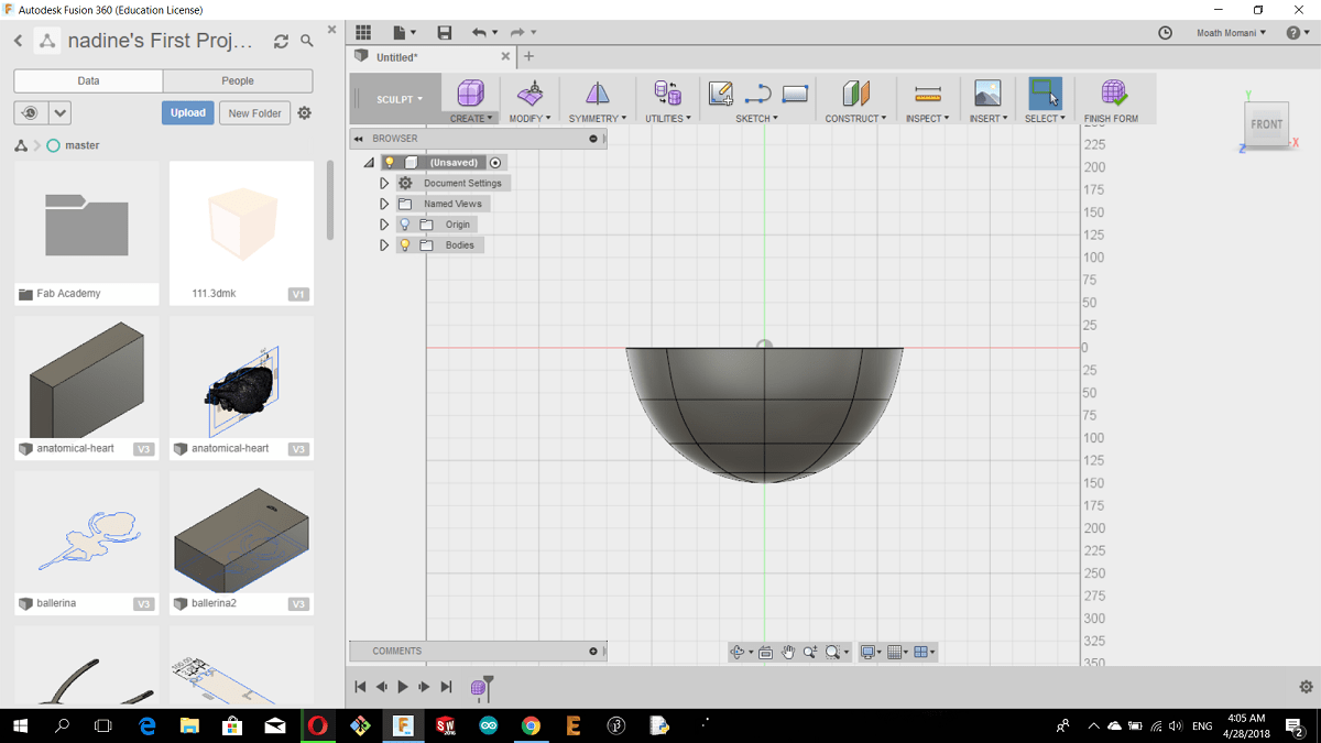
You can edit the shape as you want by right click on the selected and choose edit form
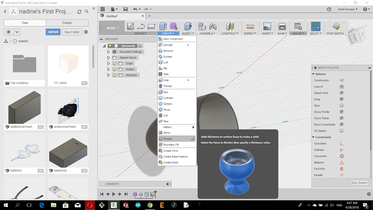
After I edited the sphere I went to model and I chose thicken from CREAT menue
After I finished the model I chose slicer from MAKE menue
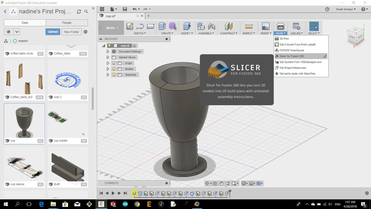
Then I chose interlocked slice
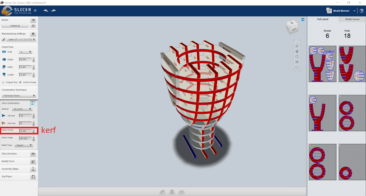
Then get plans and I saved it as DXF
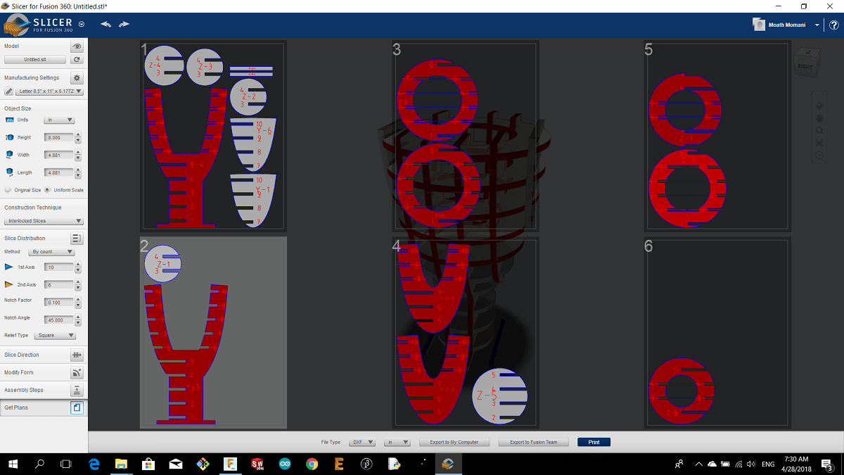
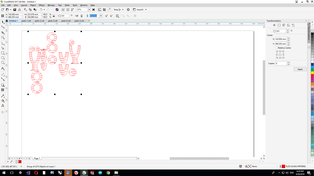
I used the cad software coreldraw
and i opened the dxf files and I made the colors RGB red 255 ,0 ,0 then i printed it


Best cutting variables
1. Plywood 5mm thickness: P=100 V=0.6 Hz=1000 kerf=0.18mm
2.Transparent Acrylic 10mm thick P=100 V=0.15 Hz=55000 kerf=0.175mm
3.Cardboard 2mm thick P=100 V=1.5 Hz2000 kerf=0.3
Use of parametric tools
Parametric design is a process based on algorithmic thinking that enables the expression of parameters and rules that, together, define, encode and clarify the relationship between design intent and design response.
For example in my design I made a rectangle shape and I designed a circle inside, and I made the relation between this circle and the cup circle equal

So whats happen when I change the dimension of one circle the other circle will changed as the same dimension
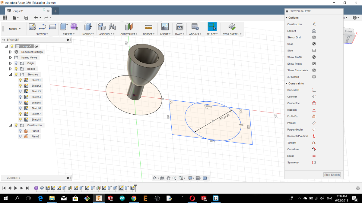
So by using a parametric cad software you can make many relation between the parts like a hole and a shaft so when you change the hole diameter the shaft will change as the same as the hole diameter
2.Roland vinyl cutter
i made my design by draft sight

i edit the colers using Corel draw software and i import the design as pdf
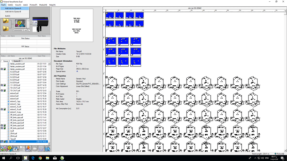
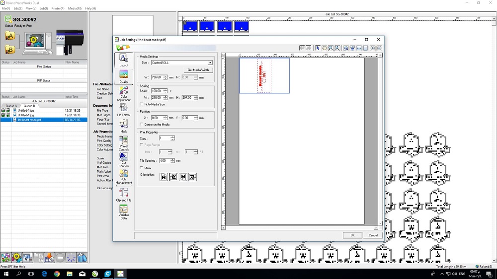
then i open it on the roland software
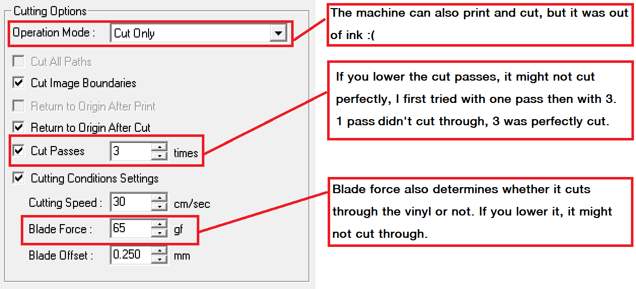
I failed in this try because the letters are very small and the cutting force is relatively low, so I repeat everything.
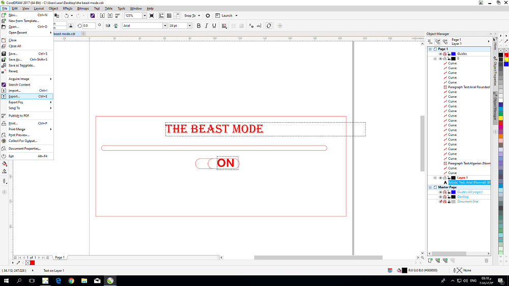
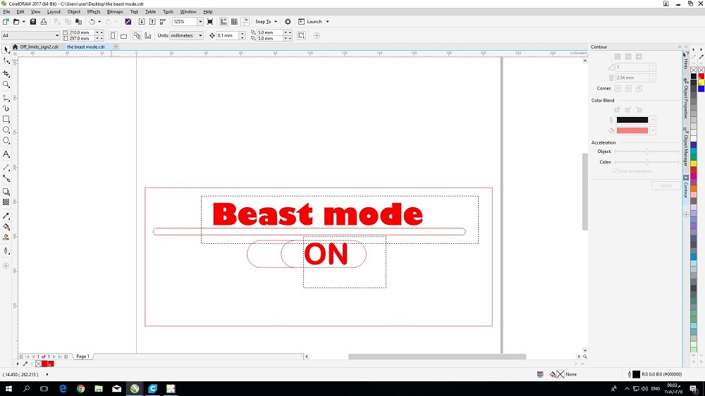
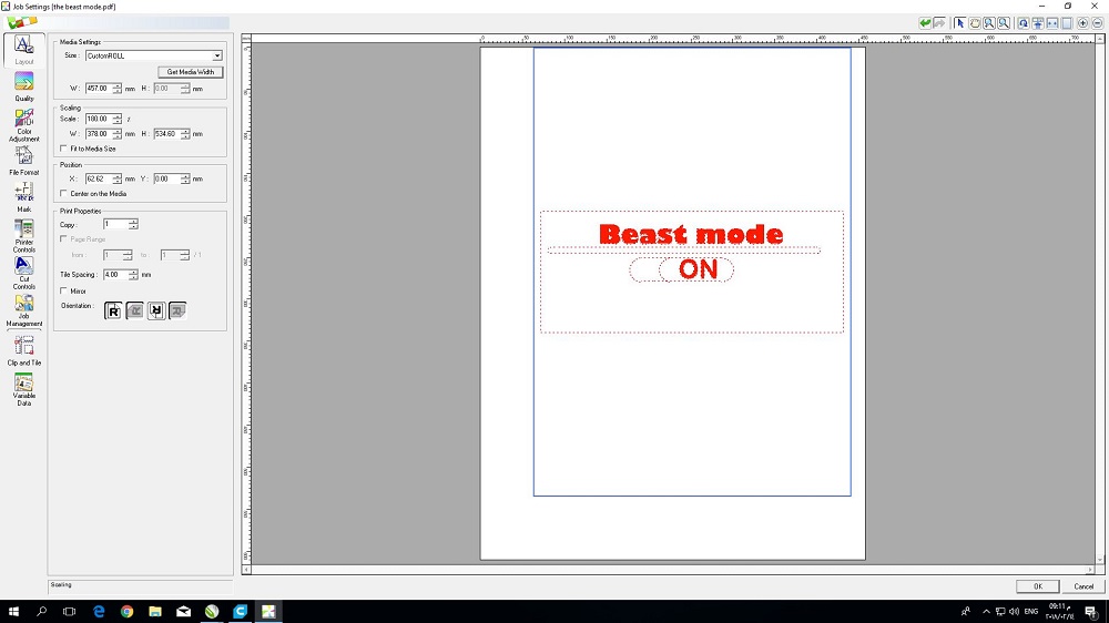
I used this time CorelDRAW software to design, I changed the font size and type by making it bigger to remove the sticker safly later avoiding the first problem
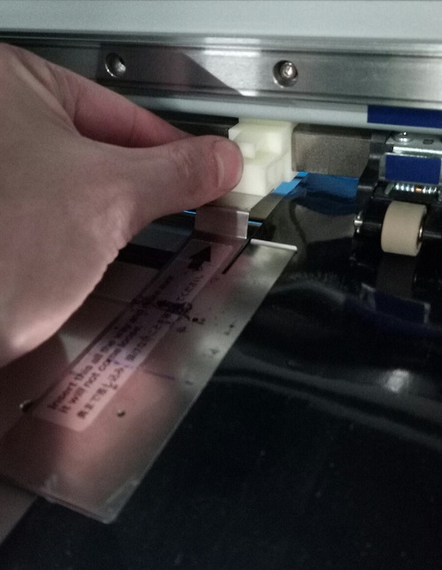
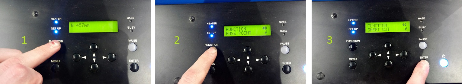
the first thing I put the limiters on the machine because we want to git the media width.
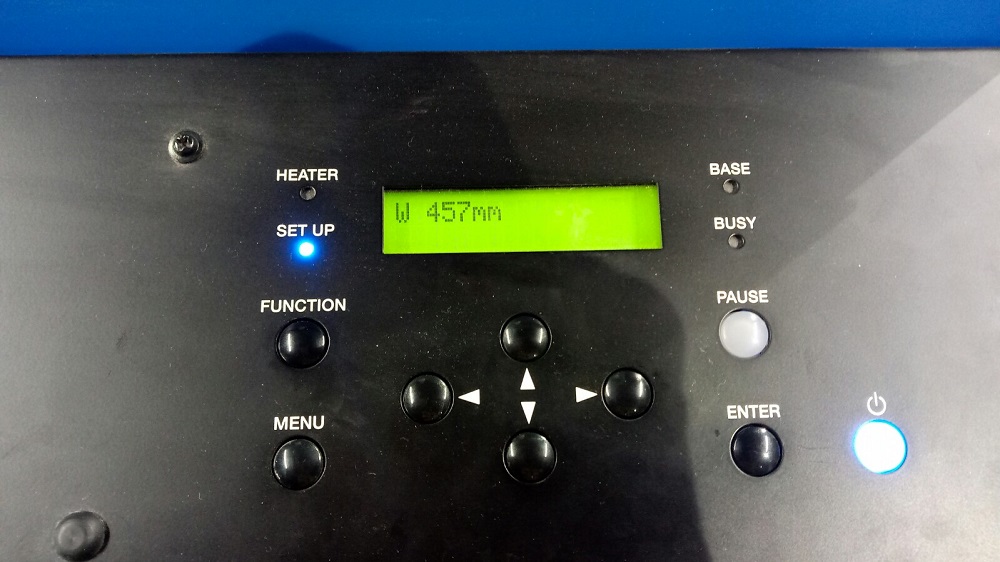
After I closed the machine it will start to calculate the media width.
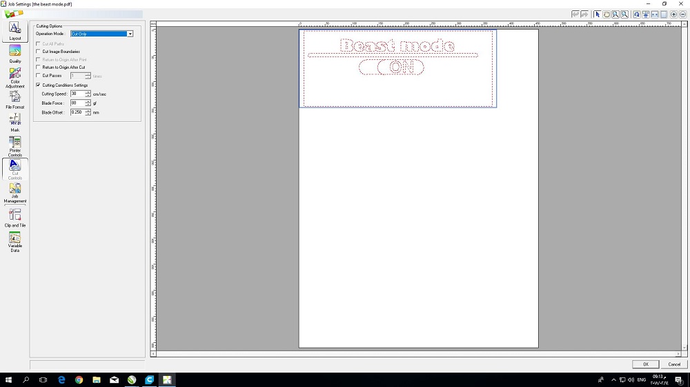
I opend the interace programe of the machine and I imported the pdf file, then got the media width on the software and I determined the cutting force and the psess
After I the machine finished the jop I cut the part that I want .
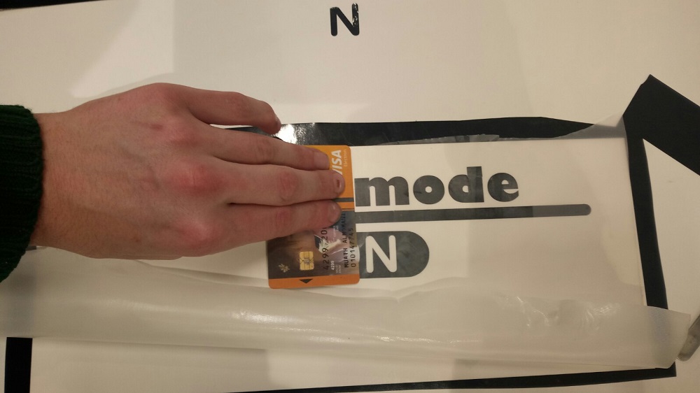
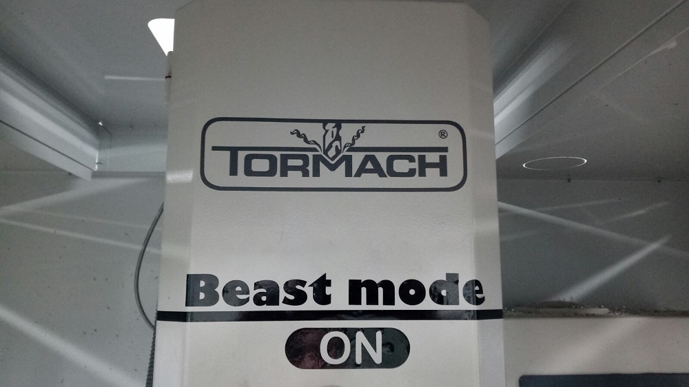
Finally I sticked the Beast mode sticker on my tormach spindle :D
1.Laser cutter
Best cutting variables
1. Plywood 5mm thickness: P=100 V=0.6 Hz=1000 kerf=0.18mm
2.Transparent Acrylic 10mm thick P=100 V=0.15 Hz=55000 kerf=0.175mm
3.Cardboard 2mm thick P=100 V=1.5 Hz2000 kerf=0.3
2.Transparent Acrylic 10mm thick P=100 V=0.15 Hz=55000 kerf=0.175mm
3.Cardboard 2mm thick P=100 V=1.5 Hz2000 kerf=0.3
Use of parametric tools
2.Roland vinyl cutter
you can download my files here
Test design for plywood and acrylic.DWG
Test design for cardboard for coreldraw.cdr
BOX.dwg in draftsight
Fusion file for the cup
Slicer files for the cup
BEAST MODE.dwg