1.CAD and CAM
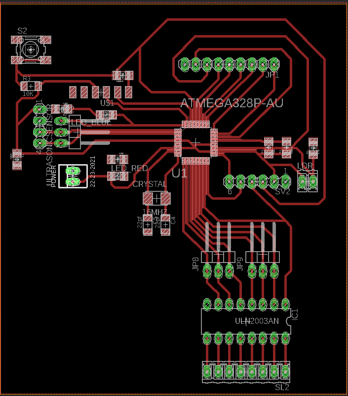
Using autodesk Eagle I designed a board with Atmega 328 and I added 4 pins for ultrasonic sensor which are the VCC, GND and pins 3 and 4 in atmega 328 pins out also I added LDR sensor connected with AD6 also I integrated my board with ULN2003AN and here is the schematic and board designs:
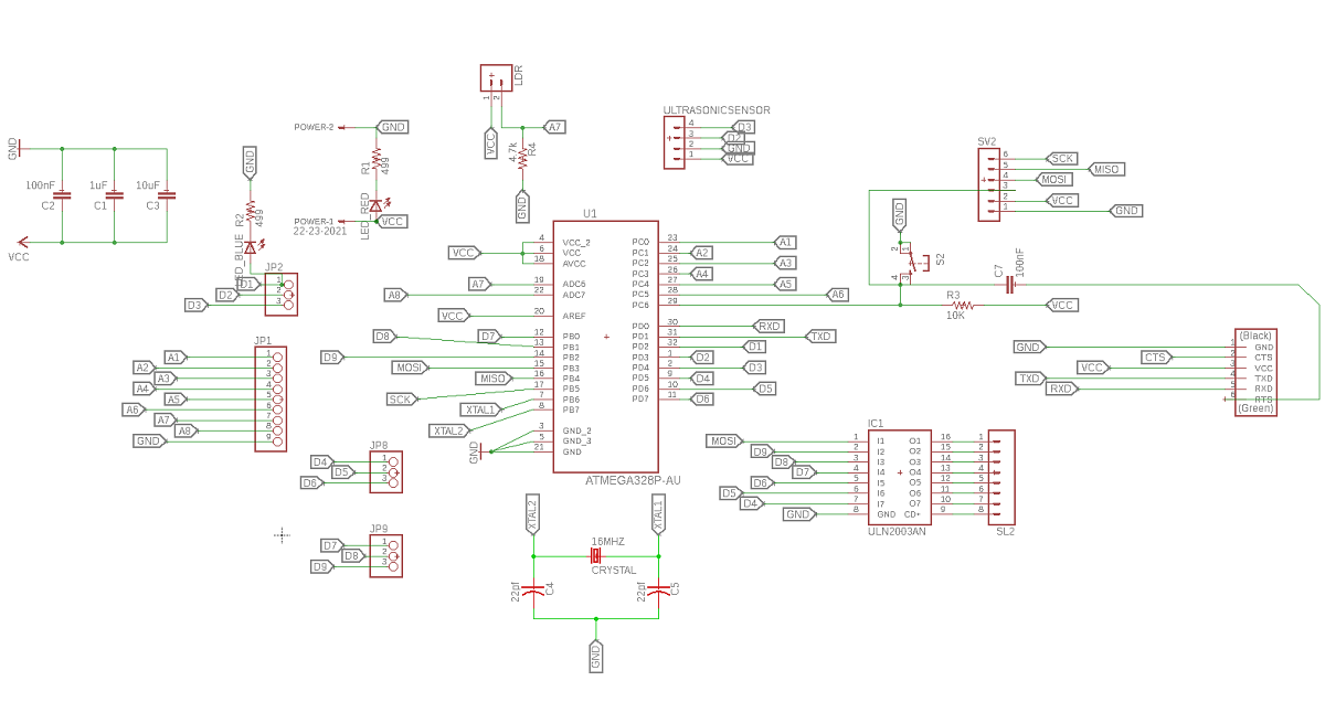
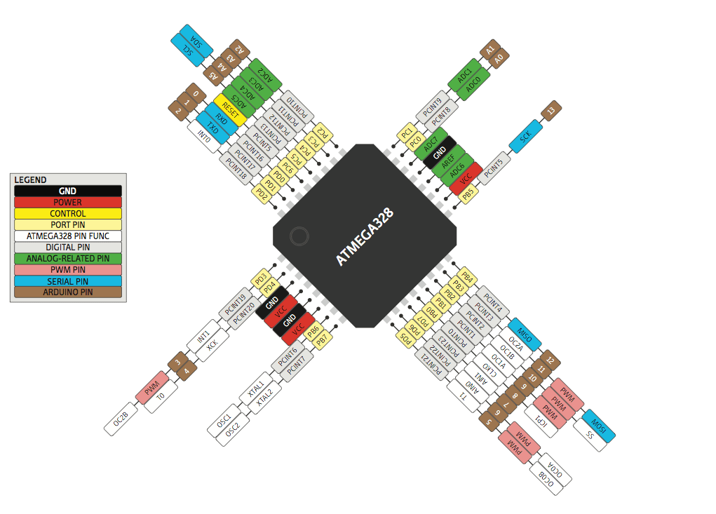
and this is Atmega 328ap pins out
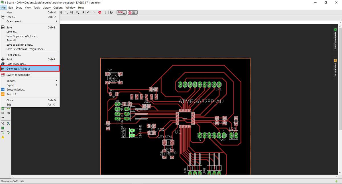
After I designed my board I used the cam processor FLAT CAM
In order to use flat cam I have to get the cam files from eagle - Board layout - file - generate cam date
And this is the Gerber and Eexellon files that I will get in a zip file .
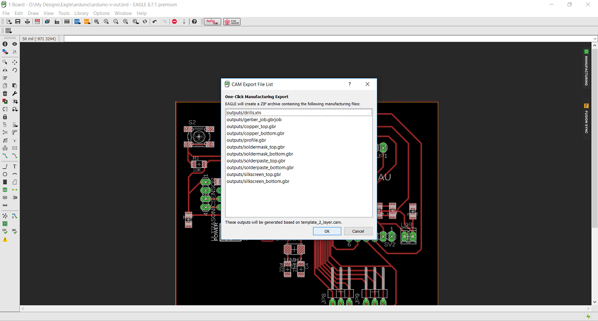
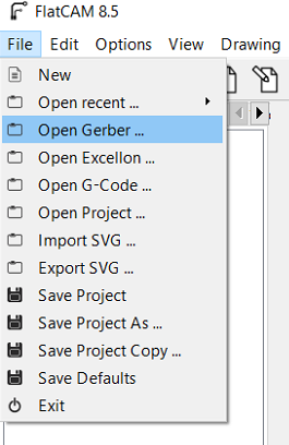
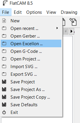
After I extracted the zip file I opened flat cam, from file I chose open gerber file wich mean I opened the file that contain the traces and the board ouside cut, then I chose open Exellon file which mean I Opened the file that contain the holes that I want to drill.
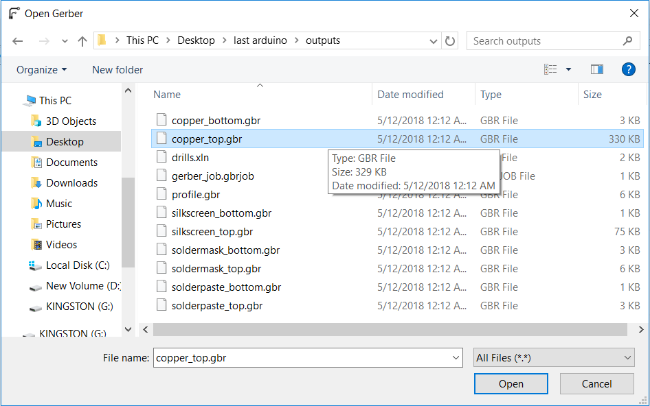
The first thing I did Is to open flat cam software then from file menue I chose open Gerber
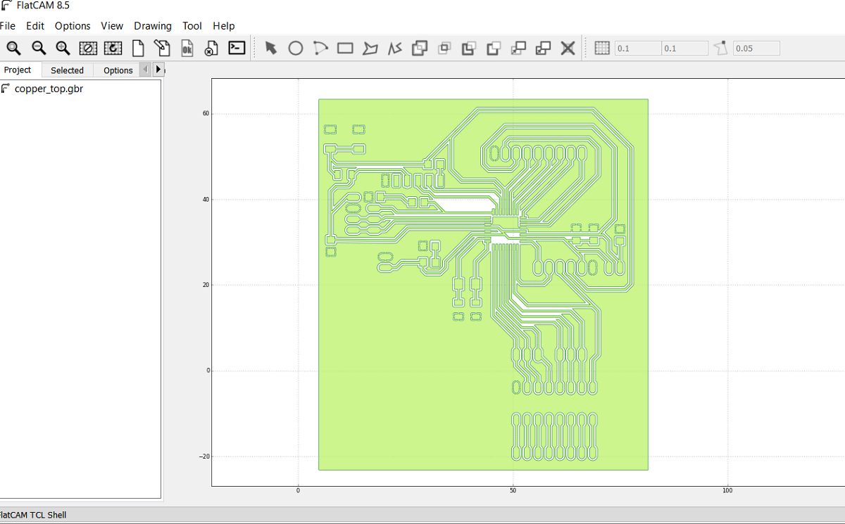
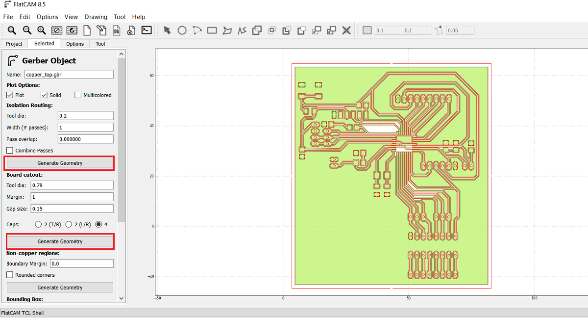
Then I selected cupper top in order to make the tool path for inside cut for the traces by 0.2 solid carbide end mill and the outside cut by 0.79 flat endmill
After I opened the selected file this is how its look like
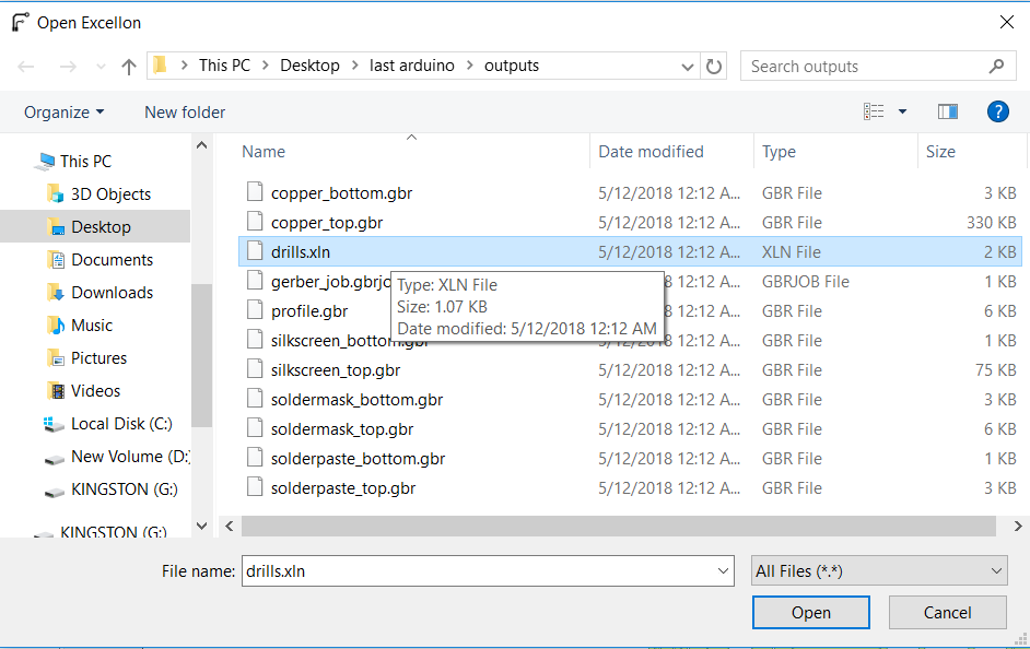
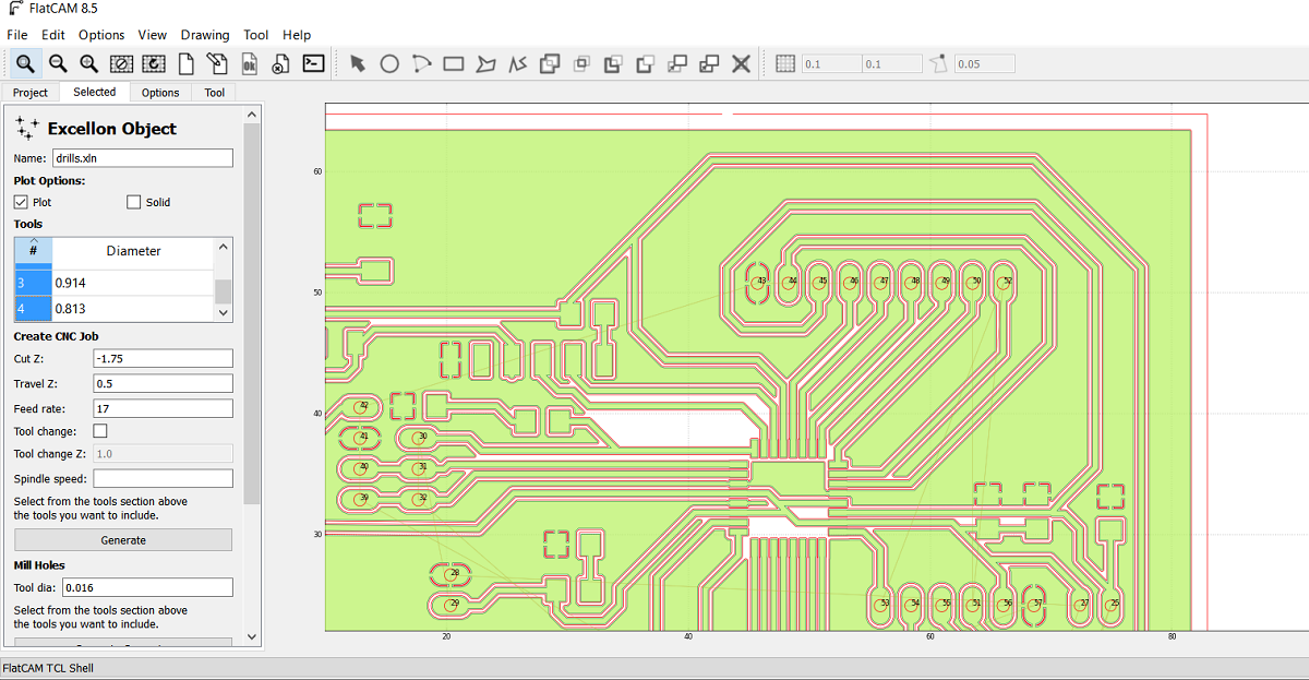
The second step is to open the Exellon file
And this is the Exellon file shown as drill.xln
After I opened the Exelon file this is the red lines as shown for the holes
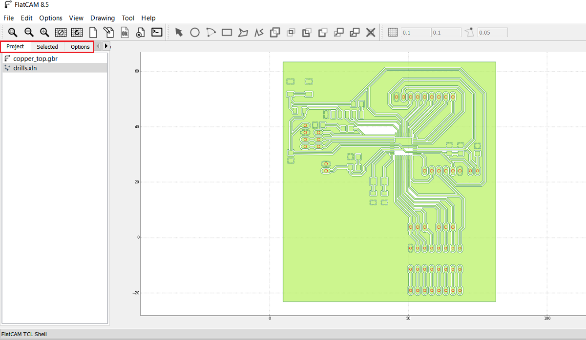
As shown in the above picture I got two jobs the first is for the inside and outside cut and the second one is for the drilling so I selected the cupper-top.gbr and then I went from project menue to select menue which in I can select the cutting variables, here I select the tool diameter of 0.2mm and the number of passes of 1 and the overlap is zero then i pressed generate geometry after this you can see the generated path for the inside cut and I did the same for board cut out and I generated the geometry as shown
Now after I finished cupper-top I went to project menue and I selected drill.xln so the main reason that forced me to learn and use flat cam instade of fabmodules is the drilling part as shown here I select all the holes diameters in this job so the 0.79 mm endmill will make all the holes but in fabmodules you have to make all the holes by black color in paint and then you can open the picture in fabmodule so using flat cam im more easy and professional
Here I put the cutting variables as shown
Now after I generated the insde, outside and drills files I got the CNC files so I opend each file.
In order to set the spendle speed I type s5000 in the exported G code this is mean the RPM is 5000 and its the maximum spindle speed in tormach PCNC 1100 and then I exported the G code as .nc
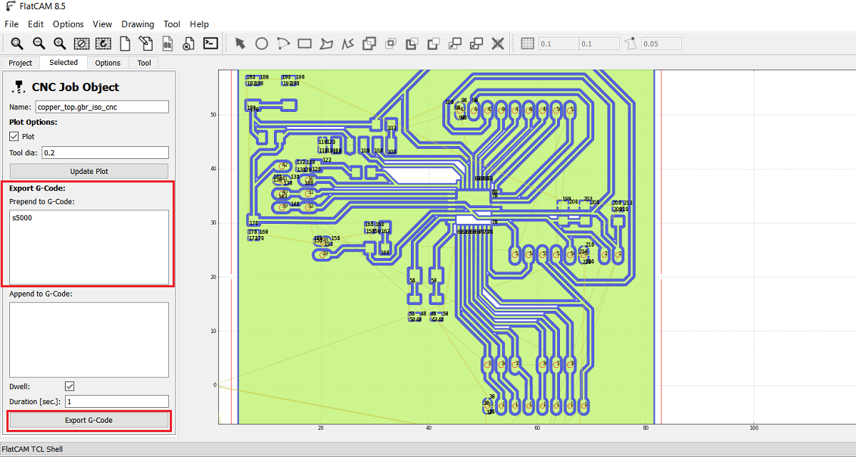
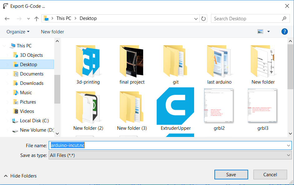
I repeated the process for the out and drill cnc files.
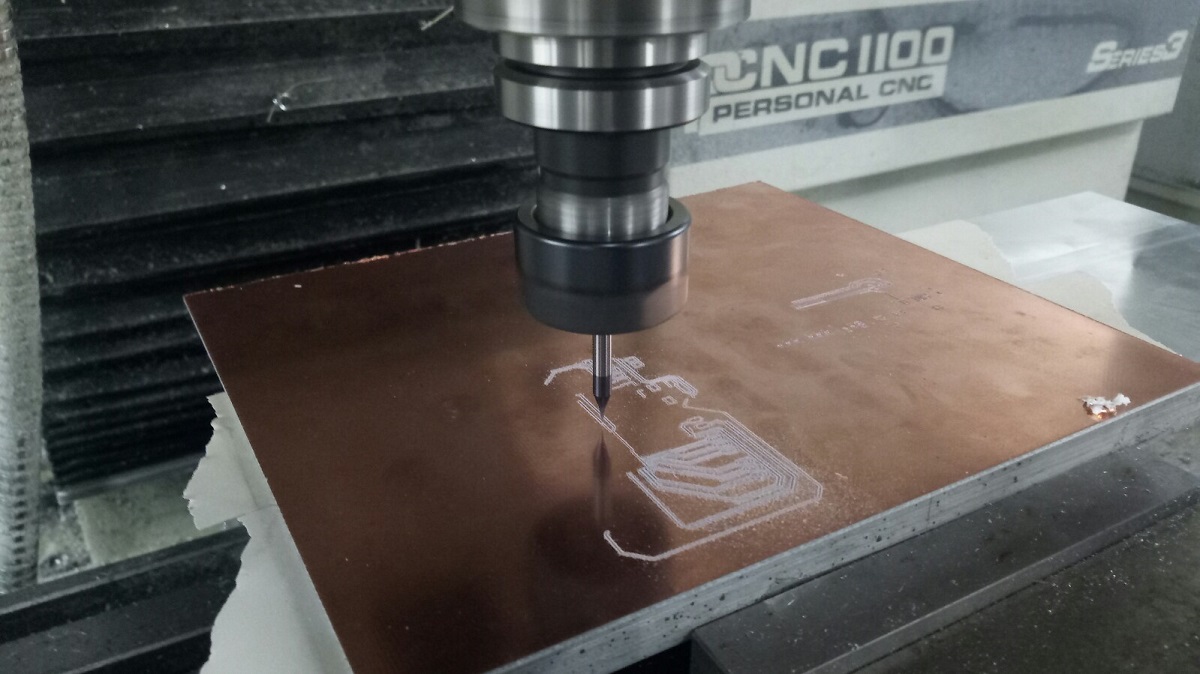
After I got the nc files I put then in a usb and the machine that I used is Tormach pcnc 1100 then I opened the file as shown
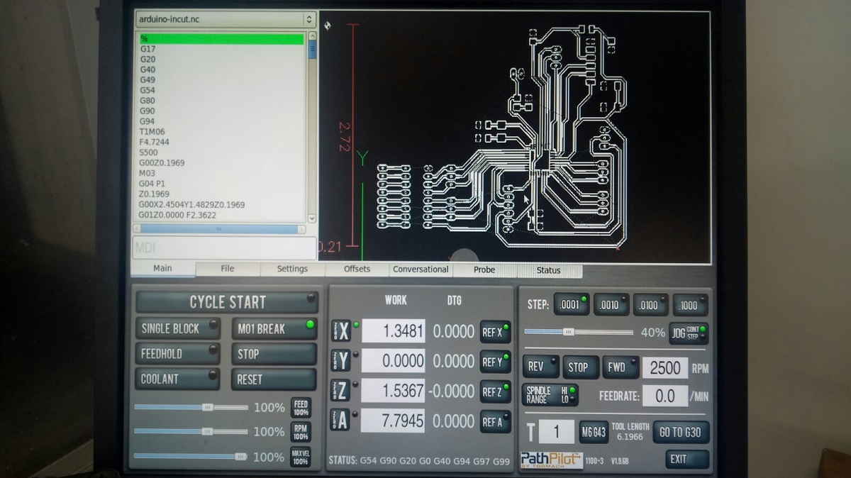
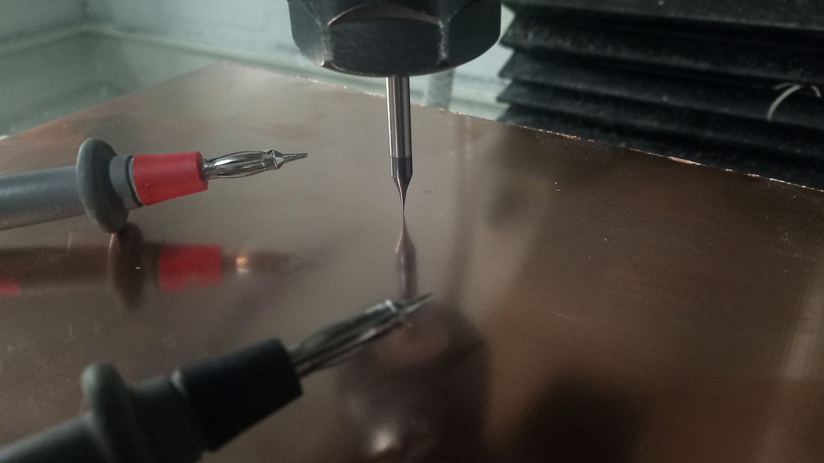
I used the Avometer to zero the z axis and thin I started the milling
And this is my board after soldering :D
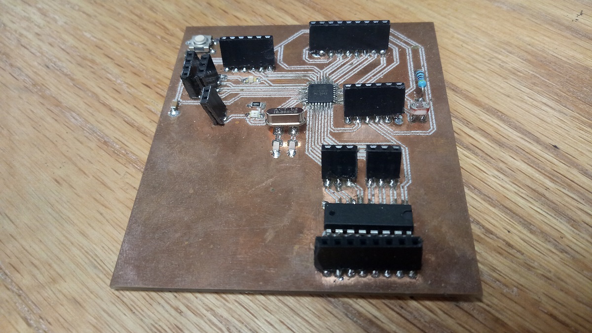
And this is the components that I used :
1.Atmega 328p is the IC.
2.Two capacitors 100nf.
3.LDR sensor.
3.Crystal 16MHz
4.Two capacitors 22pf
5.One capactor 10nf
6.One capacitor 1nf
7.Two resistors 499 ohm
8.One resistor 10k ohm
9.One resistor 4.7k ohm
10.Pin headers
11.RST buton
12.ULN 2003AN
2.programing
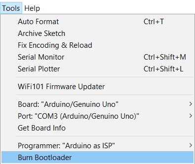
After sodering in order mo make my board programable with FTDI cable or TTL cable I have to burn bootloader and after upload a code directly using the TTL cable so to program it I used Arduino IDE, in the tools menu I selected select the right board (Arduino Uno/Genuino) and the right port after that from examples I chose Arduino ISP and I uploaded the code to arduino after I connected the board with Arduino via
RST: with Arduino Pin 10
MOSI: Master Output Slave Input with Arduino Pin 11
MISO: Master Input Slave Output with Arduino Pin 12
SCLK: Serial Clock (output from master) with Arduino Pin 13
VCC: Positive supply voltage with Arduino VCC
GND: Ground with Arduino GND
A. Ultrasonic sensor
A. Progeaming Ultrasonic sensor
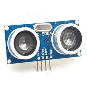
The HC-SR04 Ultrasonic Module has a range of 2cm to 700cm and it has 4 pins, Ground, VCC, Trig and Echo. The Ground and the VCC pins of the module needs to be connected to the Ground and the 5 volts pins on the my Board respectively and the trig and echo pins to any Digital I/O pin on the my Board, I made 4 pins for ultrasonic which the are pin 2 and 3 for trig and echo, VCC and GND.
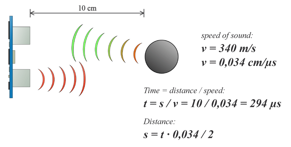
In order to generate the ultrasound you need to set the Trig on a High State for 10 µs. That will send out an 8 cycle sonic burst which will travel at the speed sound and it will be received in the Echo pin. The Echo pin will output the time in microseconds the sound wave traveled.
For example, if the object is 10 cm away from the sensor, and the speed of the sound is 340 m/s or 0.034 cm/µs the sound wave will need to travel about 294 u seconds. But what you will get from the Echo pin will be double that number because the sound wave needs to travel forward and bounce backward. So in order to get the distance in cm we need to multiply the received travel time value from the echo pin by 0.034 and divide it by 2.
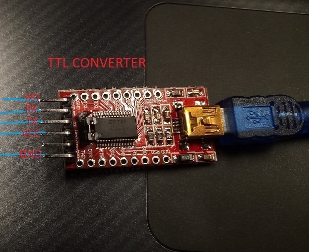
To upload the code to my board I used TTL cable
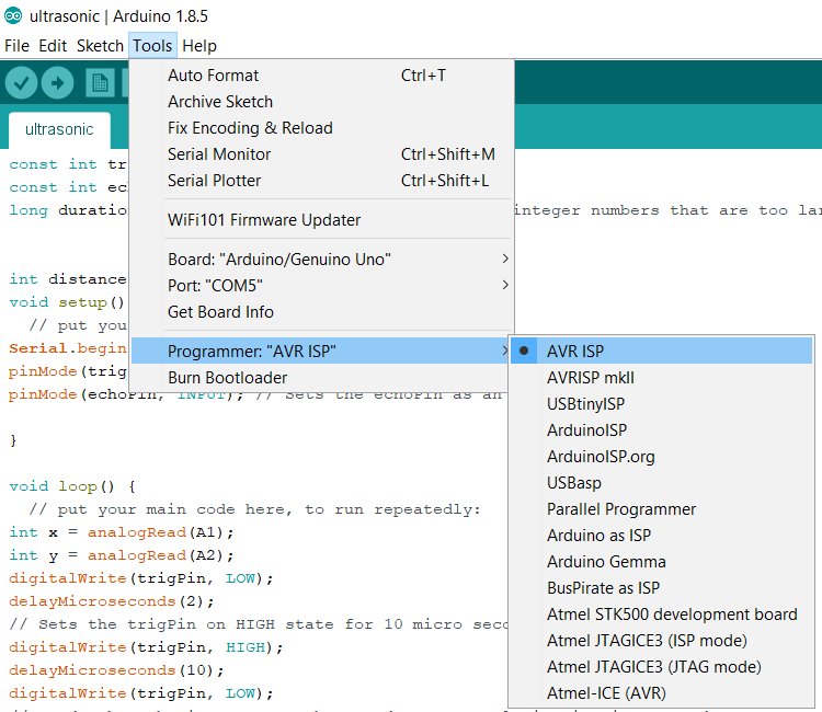
From Arduino IDE - tools I chose the following
And this is the code for ultrasonic sensor
const int trigPin = 4;
const int echoPin = 3;
long duration; //Use the Long data type to contain integer numbers that are too large to fit in the Integer data type The default value of Long is 0.


int distance;
void setup() {
  // put your setup code here, to run once:
Serial.begin(9600);
pinMode(trigPin, OUTPUT); // Sets the trigPin as an Output
pinMode(echoPin, INPUT); // Sets the echoPin as an Input

}

void loop() {
  // put your main code here, to run repeatedly:
int x = analogRead(A1);
int y = analogRead(A2);
digitalWrite(trigPin, LOW);
delayMicroseconds(2);
// Sets the trigPin on HIGH state for 10 micro seconds
digitalWrite(trigPin, HIGH);
delayMicroseconds(10);
digitalWrite(trigPin, LOW);
// Reads the echoPin, returns the sound wave travel time in microseconds
duration = pulseIn(echoPin, HIGH);
// Calculating the distance
distance= duration*0.034/2;
// Prints the distance on the Serial Monitor
Serial.print("Distance: ");
Serial.println(distance);

Serial.print("soil: ");
Serial.println(x);

Serial.print("light: ");
Serial.println(y);

delay(1000);
Serial.println("");

}
I connected the ultrasonic sensor trig pin with Atmega328 pin4 and echo pin with Atmega pin 3 also VCC and GND
Proof
B. Soil Moisture Sensor
Im going to interface an FC-28 soil moisture sensor with my board, This sensor measures the volumetric content of water in soil and gives us the moisture level, the dielectric constant can be thought of as the soil's ability to transmit electricity. The dielectric constant of soil increases as the water content of the soil increases. This response is due to the fact that the dielectric constant of water is much larger than the other soil components, The sensor gives us both analog and digital output, I will use the analog pin.
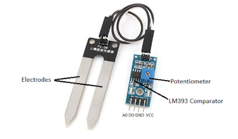
The module also contains a potentiometer, which will set the threshold value. This threshold value will be compared by the LM393 comparator. The output LED will light up and down according to this threshold value.
Specifications
The specifications of the FC-28 soil moisture sensor are:Input Voltage: 3.3–5V
Output Voltage: 0–4.2V
Input Current: 35mA
Output Signal: both analog and digital
Pin-out
The FC-28 soil moisture sensor has four pins:VCC: Power
A0: Analog Output
D0: Digital Output
GND: Ground
Now I will connect the analog pin of the module with analog pin 0 in Atmega also VCC and GND and this is the code.
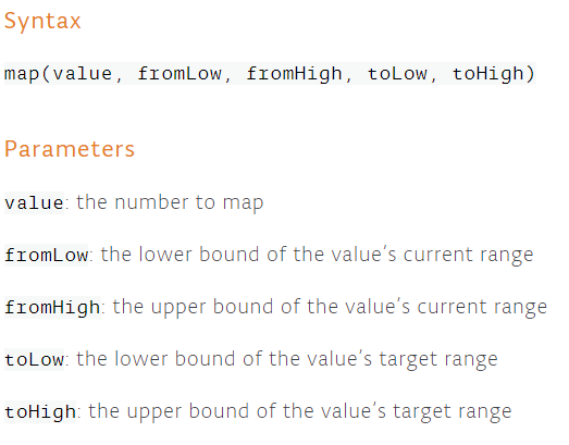
int sensor_pin = A0;
int output_sensor_value;


void setup() {
  // initialize serial communication at 9600 bits per second:
  Serial.begin(9600);
  Serial.println("sensor reading");
}

// the loop routine runs over and over again forever:
void loop() {
  // read the input on analog pin 0:
  output_sensor_value = analogRead(A0);
  output_sensor_value = map(output_sensor_value,550,10,0,100);
  Serial.println(output_sensor_value);
  Serial.println("%");
  delay(1000);        // delay in between reads for stability
}
In the loop function, I will read from the sensor analog pin and will store the values in the “out_ value” variable. Then, I will map the output values to 0-100, because the moisture is measured in percentage. When I took the readings from the dry soil, then the sensor value was 550 and in the wet soil, the sensor value was 10. So, I mapped these values to get the moisture. After that, I printed these values on the serial monitor.
I uploaded the code and this is the proof
C. LDR Sensor
WHAT IS LDR SENSOR?
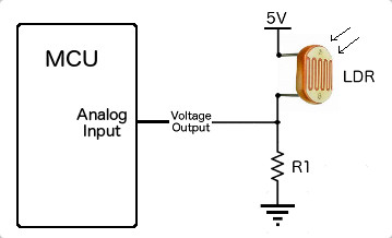
A photoresistor or light-dependent resistor, LDR, is a light-controlled variable resistor. The resistance of a photoresistor decreases with increasing incident light intensity; in other words, it exhibits photoconductivity. ... A photoresistor is made of a high resistance semiconductor.
I have already integrated LDR sensor in my board which in its connecte with analog pin 7 VCC and GNG and the next picture show the connection of LDR sensor
and this is the code
int sensorPin = A6; // select the input pin for LDR

int sensorValue = 0; // variable to store the value coming from the sensor
void setup() {
Serial.begin(9600); //sets serial port for communication
}
void loop() {
sensorValue = analogRead(sensorPin); // read the value from the sensor
Serial.println(sensorValue); //prints the values coming from the sensor on the screen

delay(100);

}
and this is the proof
3. problems
when I used fab module to generate a file.nc in order to make the board using a cnc milling which is Tormach pcnc 1100 machine insteade of roland the first time when I lunched the job in cnc milling and I had already set the Z axis zero for the machine but the machine lost the zero and I broke the bit so What I have done to avoid this problem is to lunch the machine and immediately stopped it so the endmill does not break and then took the zero of the machine for the second time and the machine will work without any problems, but in flat cam the machine will consider the firs zero as usual.
Download the files here:
1. Board schematic and Board layout
2. CAM files
3. Ultrasonic code
4. Soil moisture code
5. LDR code