Assignment 2.2
3D Design Concepts
Before starting to design with 2D design tools, an explanation of two different concepts of 3D design is reasonable: The concepts are subtractive and additive manufacturing. The main difference is in the process of shaping an object. With subtractive, i.e. traditional manufacturing, in most cases, you are chaping away bits of the original object to create a new object. In additive manufacturing which is 3D printing, you are basically starting from ‘nothing‘ ,as in the case of 3D printing, and creating an object by ‘adding' layers of an object repeatedly until you have created the desired object.
1. Subtractive manufacturing
Pro: The methods result in smoother surfaces than additive methods.
Contra: Subtractive manufacturing is less easy when producing the complex parts because very small details are harder to produce than with additive method. It lacks the key ability to create nested objects.
2. Additive manufacturing
Pro: Less waste of material because only the material that is needed is used, there is less material wasted, usually only support material.
Contra: Many 3D printers can produce at a speed of one to five cubic inches per hour which is very slow compared to other processes. Depending on the part, other manufacturing processes may be a lot faster.
3D Design: TinkerCAD
TinkerCAD is a 3D Design tool that runs in the browser. This feature allows user to be able to access their designs always and not depending on bringing their laptop everywhere.
I decided to design the watering place for my interactive crib in TinkerCAD and OpenSCAD (next paragraph underneath) to achieve the feeling that I can compare the 3D design tools. This way I might be able after testing the tools to decide which tool I prefer for which type of design.
1. At first I designed a box from the given basic shapes as the outer borders for the watering place.

2. The second step was designing the space for the water. Therefore of another basic shape box, which fits into the first one was designed.
But this box was defined as a hole shape, not as a solid to achieve that this part is cut out of the first box. To cut out the space for the water in the first box the tool 'Group'
 ![]() is used.
is used.

3. Adding a hole in the watering place ground for the water to drain (again by a hole shape and using the tool 'Group').
4. Now the shape for the water pipe was added. I used a box basic shape (solid) for the outer appearance and a cylinder shape (hole) to design the space for the water pipe inside the box. Grouping combined these two elements again.
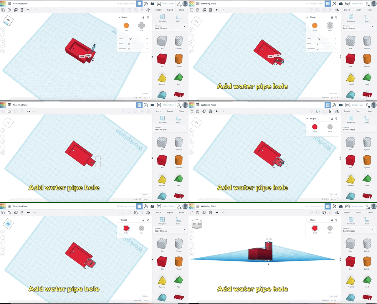
5. Finally, both boxes (the one for the water and the one for the water pipe) had to be combined using the tool 'Group' another time.

General review of TinkerCAD:
Concluding, in my opinion TinkerCAD is a tool, that provides easy understanding for a new user when he wants to design simple shapes. But the tool is not as powerful as e.g. Fusion360 in terms of options. Still because the easy accessing and because it took me only a short time to figure out the options I needed for my design I think TinkerCAD is a good option.
3D Design: OpenSCAD
Parametric Design
OpenSCAD is a new tool for me. Of course, I have heard the name but never thought about trying it before. I liked to stick to tools I knew. I guess that is just a human habit. But I got to know that designing with OpenSCAD is a way of designing that suits for me as I have a computer science background. I decided to design a basic shape for my final project as a first design step in OpenSCAD which is a watering place for the animals of my crib.
1. I used internet blogs like OpenSCAD_User_Manual: Transformations to achieve an understanding of OpenSCAD and parametric design.
2. First I took the function 'cube' to build a basic box.
3. Afterwards I looked for a command to be able to substitute some material of my cube. This can be realized by the function 'difference()'. The first line of the function describes the object that is the basis and from which parts will be substituted. The parts that are substituted are written in all the following lines of the function.
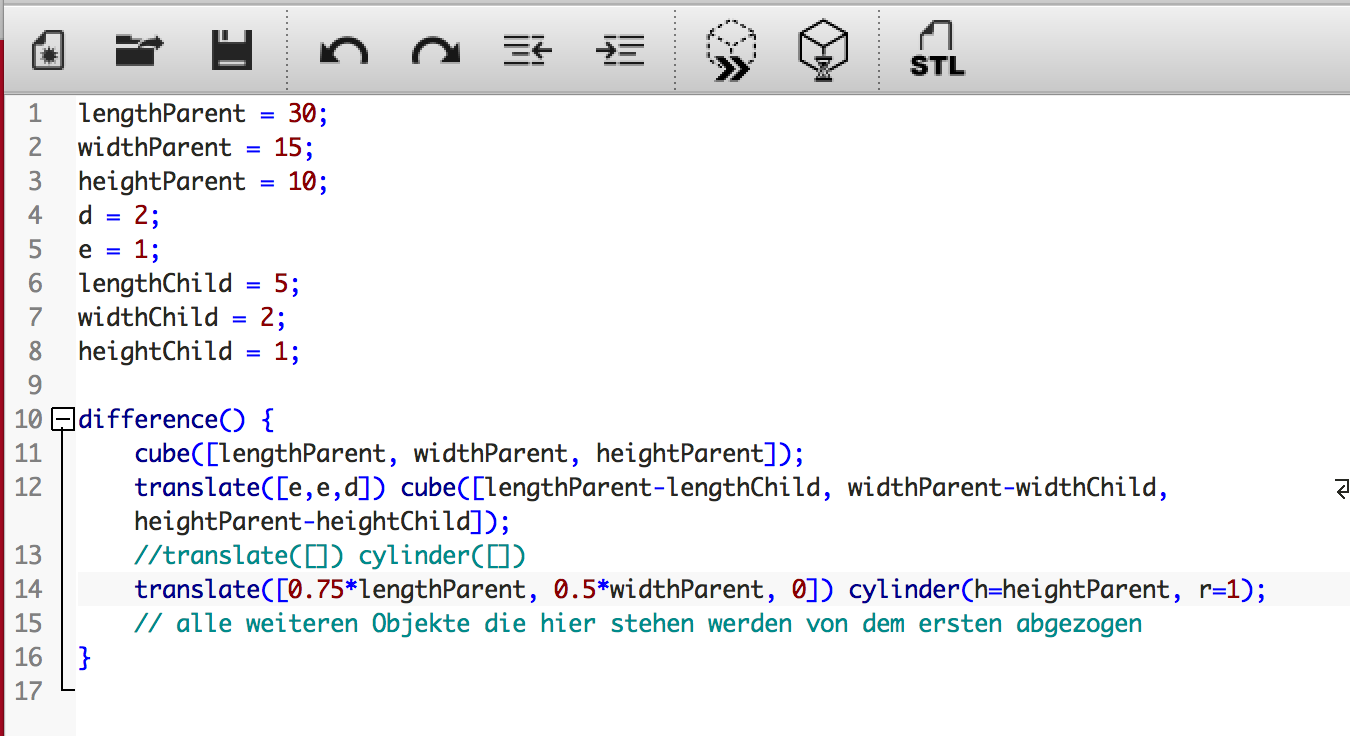
4. First, I designed my model with hard-coded dimensions. I.e. after my hard-coded model was finished I started to substitute the number by variables to achieve an parametric design.
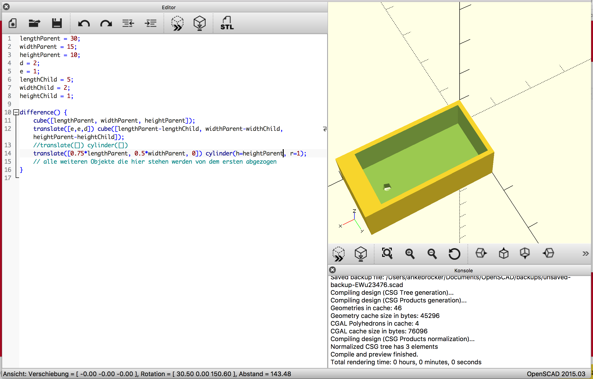
The watering place has been designed with the concept of parametric design. As I do not know yet how big the final object will be parametric design provides a big advantage compared to a hard-coded design. I am now able to change the value of the variables heigth, width and length and all other parameters are changed accordingly. Of course, getting my head into the parametric design was challenging at first, but after about 40 minutes the basic commands were clear. I think 40 minutes are a very short time and definitely worth the saved time later on.
Additive Design
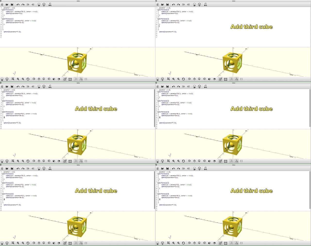
I designed a second model with OpenSCAD. This 3D model does include nested objects, which are harder to realize by subtractive manufacturing. Therefore, this model was realised with the concept of additive manufacturing.
3D Design: Fusion 360
Fusion360 is not in general a free tool but students can get a three year free version.
1. For me the Fusion360 interface looked very powerful when I saw it the first time. Because it offers so many different options and tools I decided to read through a few tutorials to achieve an idea of how to create basic shapes. The following two links were really helpful.
Helpful links:
Tutorial Fusion360 Basic sketching
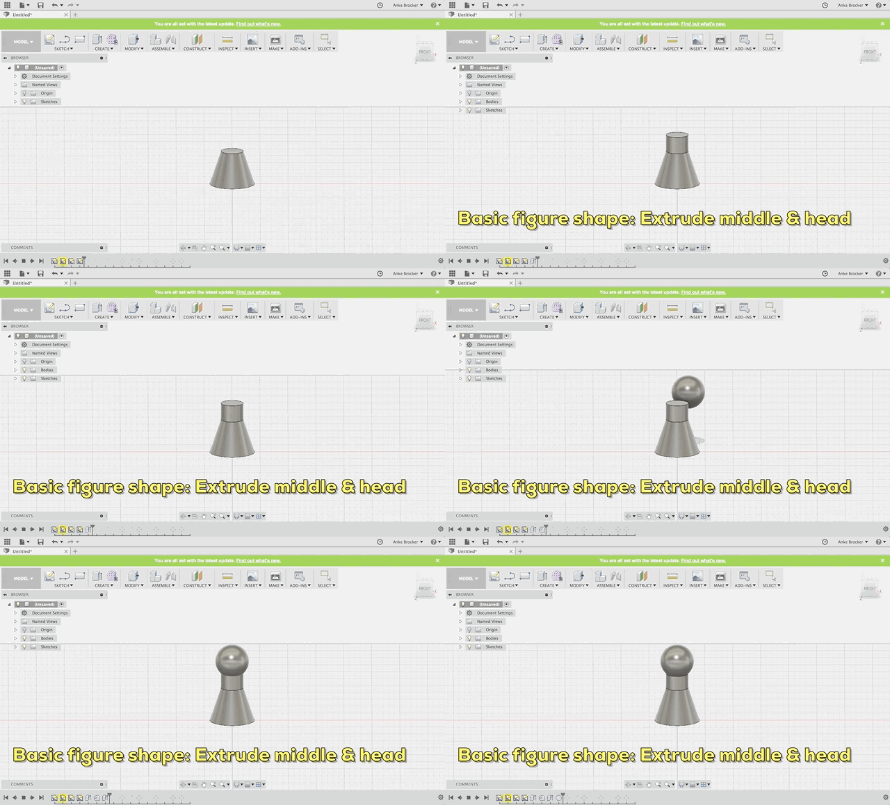
2. I decided to design an approach for a basic shape for the figures of my interactive crib. This figure consists of different parts. The first one is a cone cut off at the upper side. To design this I watched the following video: Cone.

3. For the middle part of the figure I used the 'Extrude' option  which allows the user to change a 2D layer into a 3D object. I took the top layer of the bottom cone to extrude.
4. Next the head of the figure was designed. For that the basic shape of a 'Sphere'  was placed in the model and moved into the right position on top of the middle part.
5. For the arms of my model I used the shape of a 'Sphere' agin. Two small sphere signify the arms of the figure.
6. The last step was combining all components. Therefore, I used the option 'Modify/Combine'  after mark the hole figure.

General review of Fusion360:
After collecting some first experiences with Fusion 360 my impression is that it takes a lot more time and training to understand all features. Compared to TinkerCAD for me it was a little harder to dive into it. But I really like the timeline that keeps track of what happened in your project and opens easy access to earlier versions of the model.