Wk11. Input Devices
Individual assignment: measure something: add a sensor to a microcontroller board that you have designed and read it Group assignment: measure the analog levels and digital signals in an input device
Input Data
This week we are looking at sensors or input devices and how we can retrieve analogue data into our microprocessors.
Getting Data on ATtiny45
PORTS:
Each microprocessor pin has a register that controls whether it is an “input” or an “output” - has a register that can read the bits in and has a register that can write the bits out.
ANALOGUE COMPARATOR:
Measuring the difference between two voltages. Whats good about this is it can do it very quickly, in a single clock tick.
ANALOGUE DIGITAL CONVERTER (ADC):
This is a multi-functional part of our tiny microprocessors which takes an analogue voltage in and gives a digital value. I need to understand more about how this works. Here is how to make sense of the data sheet schematic:

BIT TIMING:
For most of Neil’s example he is generating the serial data to communicate with the computer in his c code. In this code you can find the bit time which defines how long each bit lasts. He uses the internal ATtiny 45 clock (no external crystal like in the Hello World Board) to keep the board simple, but and depending on the speed of the clocks it may or may not be in the correct range. So need to check the timing in the code to control the bits.
Individual assignment
This week I was interested in trying out the Hall sensor to try and measure the RPM (rotations per minute) on my turbine. A Hall effect sensor is a transducer – meaning a device that converts energy from one form to another – that varies its output voltage in response to a magnetic field. Hall effect sensors are used for proximity switching, positioning, speed detection, and current sensing applications.
HALL Sensor
Here is Neil’s board layout, and as you you can see, also from the digikey link in this weeks assignment, he references the A1324 which is a “Low Noise, Linear Hall Effect Sensor ICs with Analog Output”.
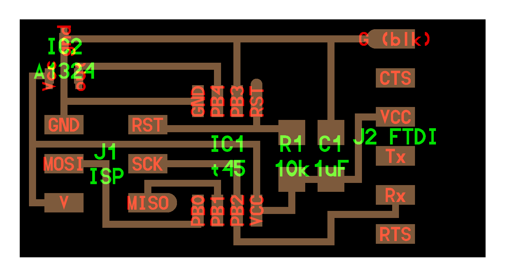
Looking through our Barcelona electronics parts, I was only able to find the A1302 “Continuous-Time Ratiometric Linear Hall-Effect Sensor” - see data sheet below. Furthermore, I noticed that the assigned component was missing from the Fab library in Eagle, but I was able to find the A1302 in the Eagle general library.
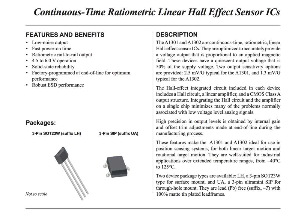
Looking over both data sheets, the components are virtually the same (the 3 pin package and footprint to start with) but it seems the A1324 adds enhanced temperature stability, low-noise output and enhanced EMC performance for stringent automotive applications. Details I won’t be picky about for this assignment, but good to bear in mind.
Redesigning the board
Below I redesigned Neil’s board in Eagle, using the ATtiny 45. Initially I had some trouble getting my GND trace to fit in-between the legs of the component, as you can see here:

Therefore I reorganised the board like so:
 |
 |
Apart from a bit of confusion over the Hall sensor in question (mentioned above) this part went fine. Here my traces and milling strategy on the Fab Modules:
 |
 |
Milling, Stuffing
The milling and stuffing seemed to go without hitch.

 |
 |
Programming
First off I wanted to program the board using Neil’s code and python program. As with the embedded programming week, I downloaded his hello.mag.45.c and makefile as well as his serial python program.
Compile the code, this generates the .hex and .out file
➜ make -f hello.mag.45.make
Program the board with my FabISP.
➜ make -f hello.mag.45.make program-usbtiny
Activate Python 2.7
➜ source activate py27
confirm
➜ python --version
Python 2.7.14 :: Anaconda, Inc.
Run the py serial program:
(py27) ➜ python hello.mag.45.py /dev/tty.usbserial-A505DVC9
 |
 |
And here it is working with one of my neodimium magnets:
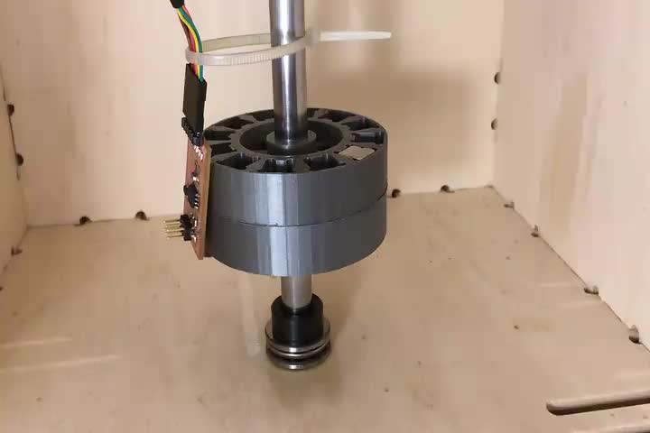
Here I’m testing it with my rotor design
More to come on reprogramming the Hall sensor input.
You can download my design files for week 11 from my Gitlab repository.
Input Device for Final Project
For my final project I redesigned the Hall sensor board to make my tachometer. Here are my PCB designs in Eagle. Specific to this tachometer are a 20 Mhz resonator because i figured the timing needs to be very accurate. I also added two LED’s. The first (green) I wanted to indicate/blink on each rotation, and the second (red) I was thinking could indicate as certain threshold (like to indicate when the turbine is rotating below a critical rpm) so as to warn when there is a lower generator/voltage so drawing disproportionately from the batteries/capacitors.
 |
 |
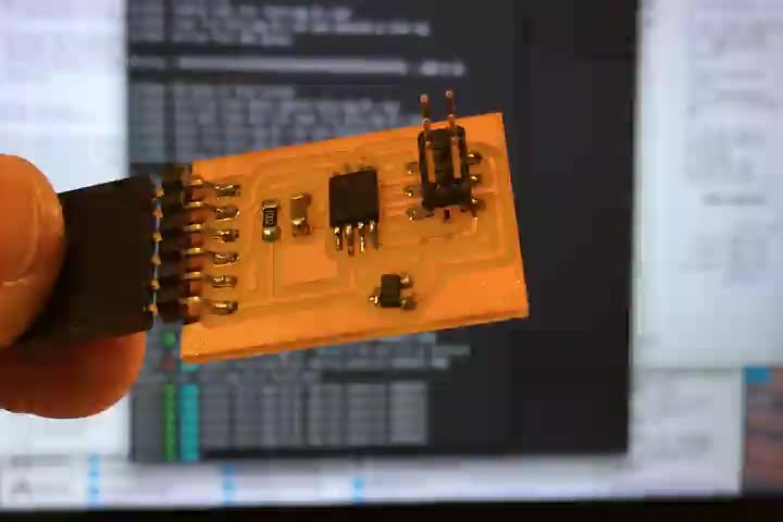
I also added a button to Pin 10 with the idea that if I wanted i could press it to turn the LED’s off to conserve power. Here is the PCB, milled and soldered. As you will notice I extended the reach of the tiny hall sensor because I wanted it to get as close to the axis as possible.
 |
 |
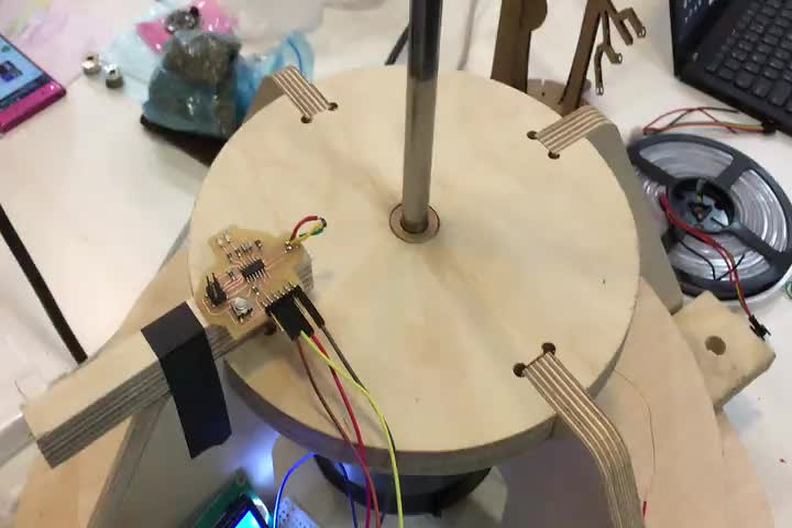
Here ere I am testing my tachometer, using an Arduino attached to an LCD display to read the serial output.
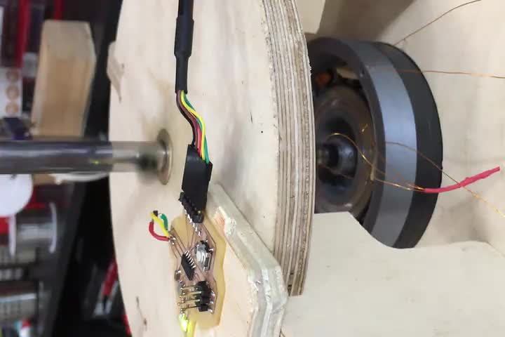
And here is my tachometer working with while I was testing my generator, and I am reading the RPM and Hz readings directly in the serial monitor.
Programming
Here is the code I used to program the tachometer. Please read the //comments for specific explanations:
//Tachometer Board Attiny44

#include <SoftwareSerial.h> // include the Software serial library to run serial on Attiny44
SoftwareSerial mySerial(0, 1); // declare my serial ports 1 and 0 (TX, RX)


const byte sensorPin = A2; // set hall sensor pin PA2 = pin4 = A2
const byte buttonPin = A3;  // set buttonPin = A3
const byte ledPin1 = 8;  // Red LED pin 8
const byte ledPin2 = 7; // Green LED pin 7


byte sensordigital; // set global variable for sensing the pulse
byte prevsensordigital; // set global variable for recording the previous pulse value
volatile byte counter; // set counter variable

int rpm; // set rpm variable
unsigned long lastmillis; // let

void setup() {

  //set sensorPin (A2) as INPUT
  pinMode(sensorPin, INPUT);
  pinMode(buttonPin, INPUT);
  pinMode(ledPin1, OUTPUT);
  pinMode(ledPin2, OUTPUT);

  counter = 0;
  sensordigital = 0;
  prevsensordigital = 0;
  rpm = 0;
  lastmillis = 0;

  //Set the baud rate 9600 bits per second
  mySerial.begin(9600);

}

void loop() {

  // analogRead (ADC) sensorPin to provide int = SensorValue
  int sensorValue = analogRead(sensorPin);
  int  Maxthresh = 515;
  int Minthresh = 510;
  prevsensordigital = sensordigital; // saving the pervious sensor value and printing the current one

  // button print sensorValue
  if (digitalRead(buttonPin) == 0) {
    mySerial.println(sensorValue);
    digitalWrite(ledPin1, HIGH);
    }
    else {
    digitalWrite(ledPin1, LOW);
    }


  if (sensorValue >= Maxthresh || sensorValue <= Minthresh) {
    // mySerial.write("1");
    digitalWrite(ledPin2, HIGH);
    sensordigital = 1;
  }     else {
    // mySerial.write("0");
    digitalWrite(ledPin2, LOW);
    sensordigital = 0;
  }

  if (prevsensordigital == 1 && sensordigital == 0) { //
    counter ++;
    }

   if (millis() - lastmillis >= 1000) {
   rpm = counter * 60;
   mySerial.print("RPM="); //print the word "RPM" and tab.
   mySerial.print(rpm); // print the rpm value.
   mySerial.print(" Hz="); //print the word "Hertz" and tab.
   mySerial.print(counter); // print the rpm value.
   lastmillis = millis();
   counter = 0;
   }

   delay(5);   // Wait 5 milliseconds

}
You can download my Eagle PCB files here.
