13 - output devices
led array
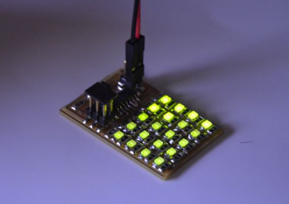
I'm so fascinated for the light effects, that's why I decided to make the LED array.
Before you start, I suggest you to look at these websites that kindly our teachers have shared with us, about
Charlieplexing and its theory.
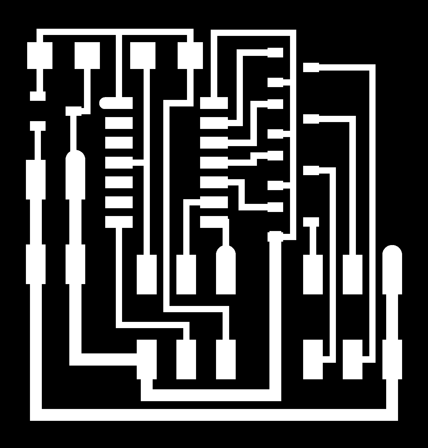
After cutting the board with our Modela, I started to solder the component... and wow! there are a lot! it was a great challenge but I'm happy to have succeeded at the first attempt.
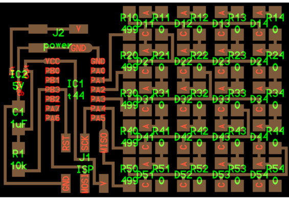
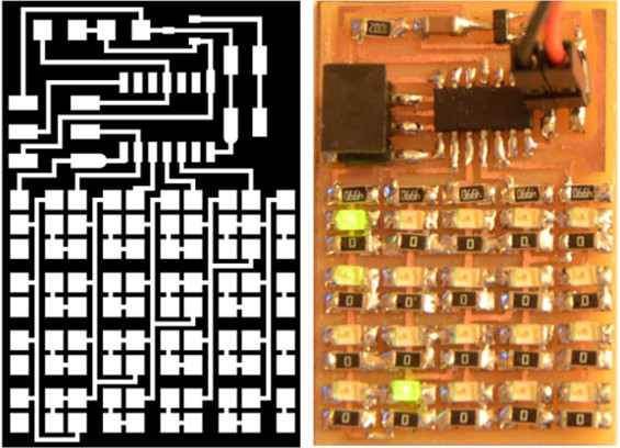
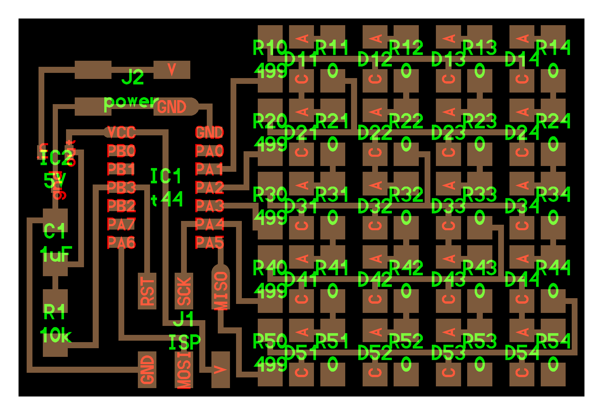
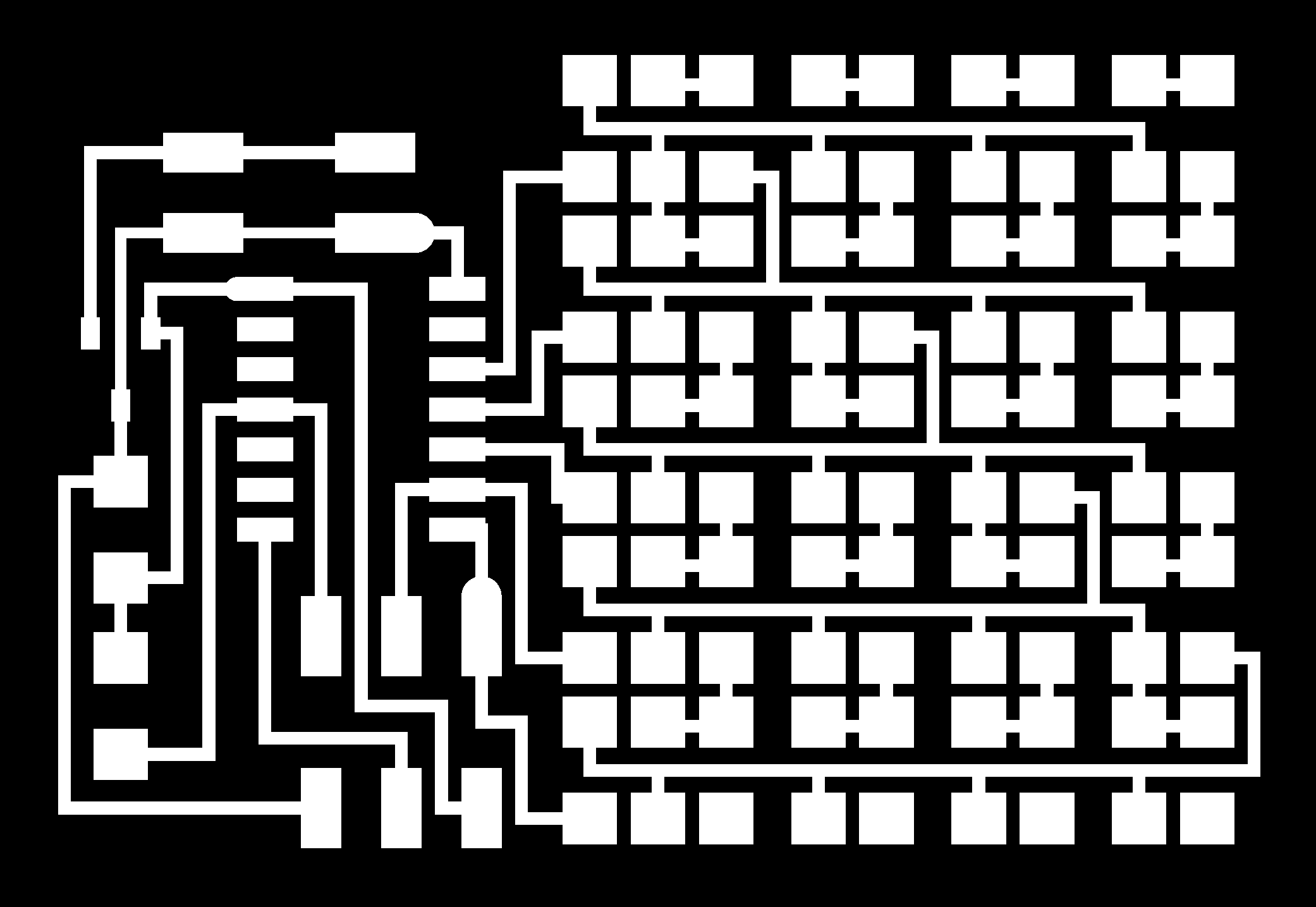
[board - traces - outline]
[x1 ATtiny44, x1 Resistor 10k, x1 Capacitor 1uf, x1 Regulator (IC2)5V, x5 Resistor 449ohm, x20 Resistor 0ohm, x20 LED]
When I connected the board to the FabISP, I compiled it with Neil's C code:
make -f hello.array.44.make program USBTiny
[C file - Makefile]
Watch my video to see how is this effect!
LED Array - output device from Lorenzo Negri on Vimeo.
step motor - unipolar
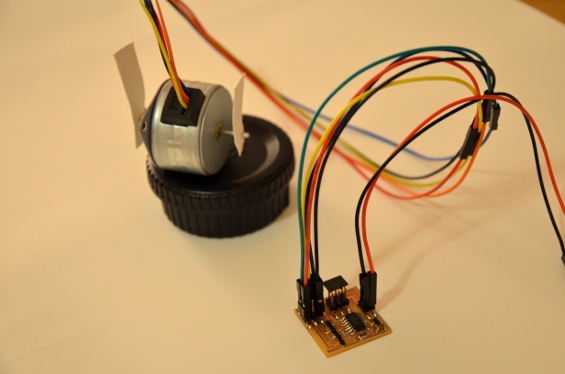
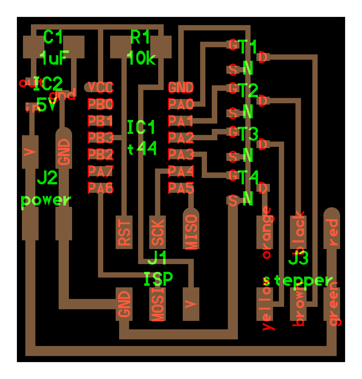
I tried to make also a Step motor (here you can find a short but effective explanation about the world's motor) in order to see if it was strong enought for my final project (pinball or interactive pinball). Once milled and welded I was almost ready to see my motor moving. [board - traces - outline]
[x1 ATtiny 44, x1 Resistor 10k, x1 Capacitor 1uf, x1 Regulator (IC2) 5V, x4 Transistor]
[C code wave - Makefile]
Sincerely it was a bit hard to connect the wires in the right way, because my board Step motor has only 5 pins and the board 6; After comparing Neil's motor with mine, I figured out how were the right connections:
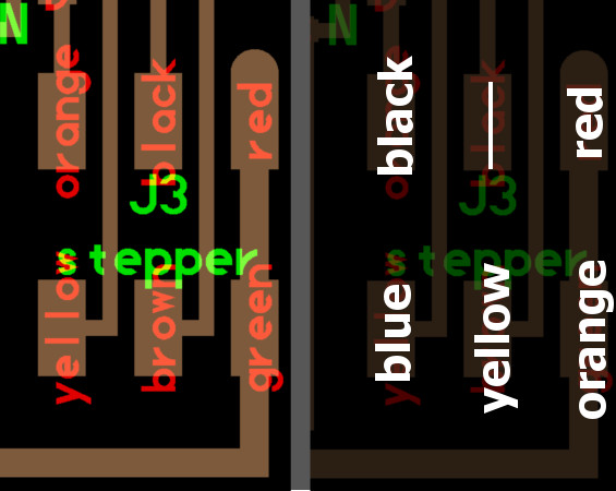
..and here below you can see the movement!
step motor - output device from Lorenzo Negri on Vimeo.
lcd
I worked also with LCD (mine has this data sheet) directly with my Arduino.
You can see my progress inside the page: "development of my project"

