10 - input devices
This week's assignment was to make some sensor boards, flash them with the c code and finally display their values using python script.
I made several board,both to better understand how they work and to practice with the milling machine and welding.
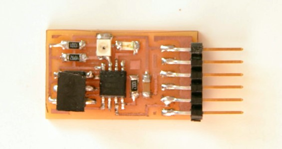
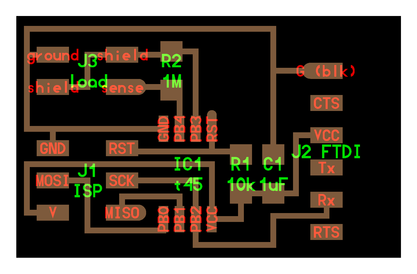
load sensor
I started cutting my PCB [board - traces - outline] at the Modela and then I weld the all the components.
[x1 ATtiny 45, x1 Resistor 10k, x1 Resistor 1M, x1 Capacitor 1uf]
This time was much easier to solder because there were few components.
![]()
Meanwhile I also downloaded the C file, the Makefile and the PY code.
Once I finished, I opened CMD and looked for the folder where I saved the Makefile.
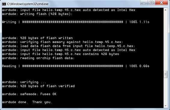
(So in my case I typed "cd documenti\fabacademy\10 - input devices\Load") After plugged the Fab ISP and the load board to the computer, I also connected each other for programming. At this point I typed:
"make -f hello.load.45.make program-usbtiny" in order to make it flash. (below there is the screnshot of CMD).
![]()
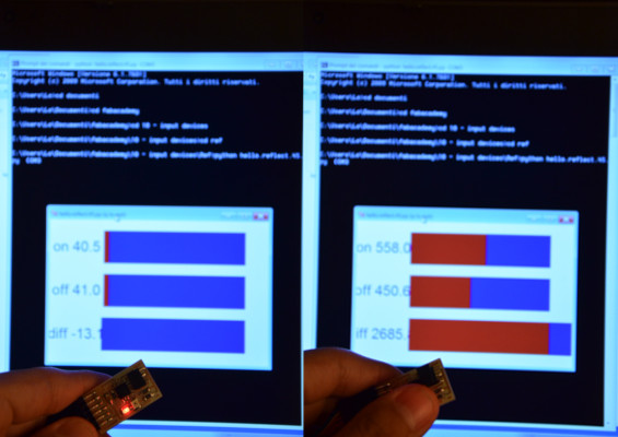
Finally I typed "python hello.load.45.py COM3 (COM3 = it's my port where is connected my board) and it work perfectly! here is the video:
load sensor - Input device from Lorenzo Negri on Vimeo.
Since these steps where identical for the other boards, below are just photos and files.
light sensor - phototransistor
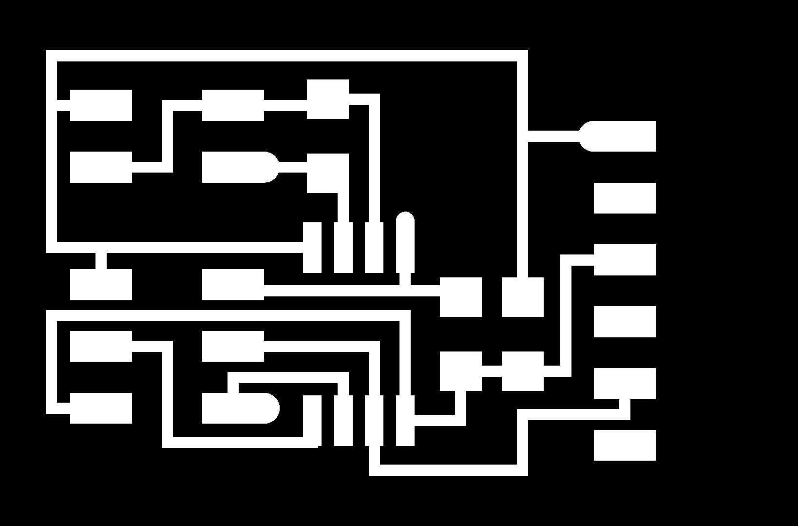
[board - traces - outline]
[x1 ATtiny45, x1 Resistor 10k, x1 Resistor 49,9k, x1 Capacitor 1uf, x1 LED - Watch out to the side of cathode and anode! Usually with these types of LED, the cathode-side is indicated with a small triangular groove]
C file - Makefile - PY code
![]()
light sensor - input device from Lorenzo Negri on Vimeo.
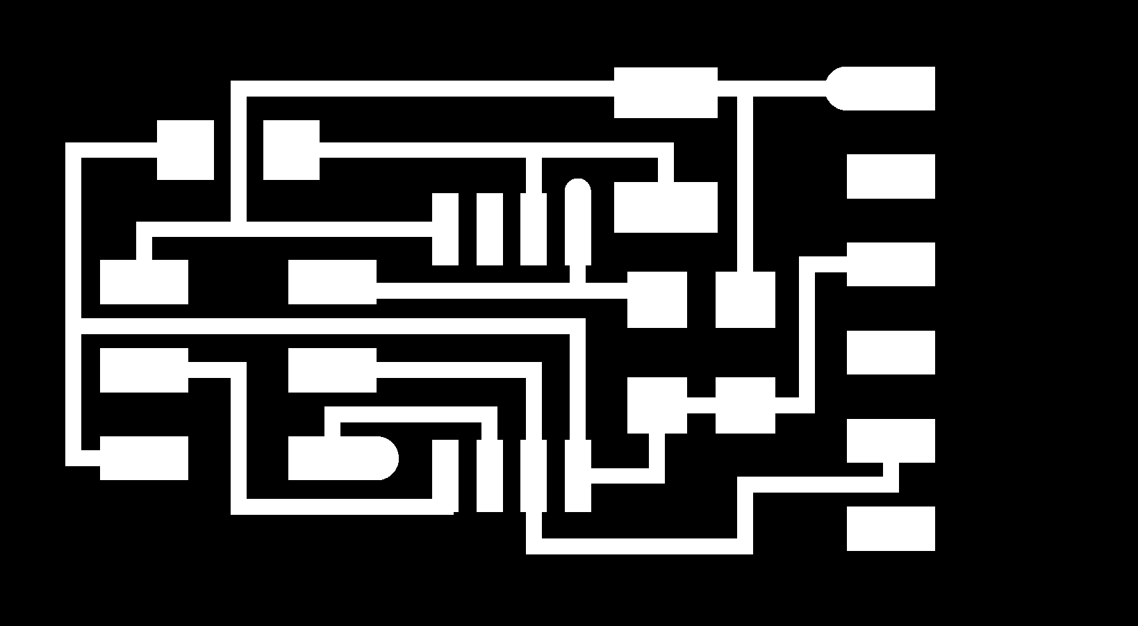
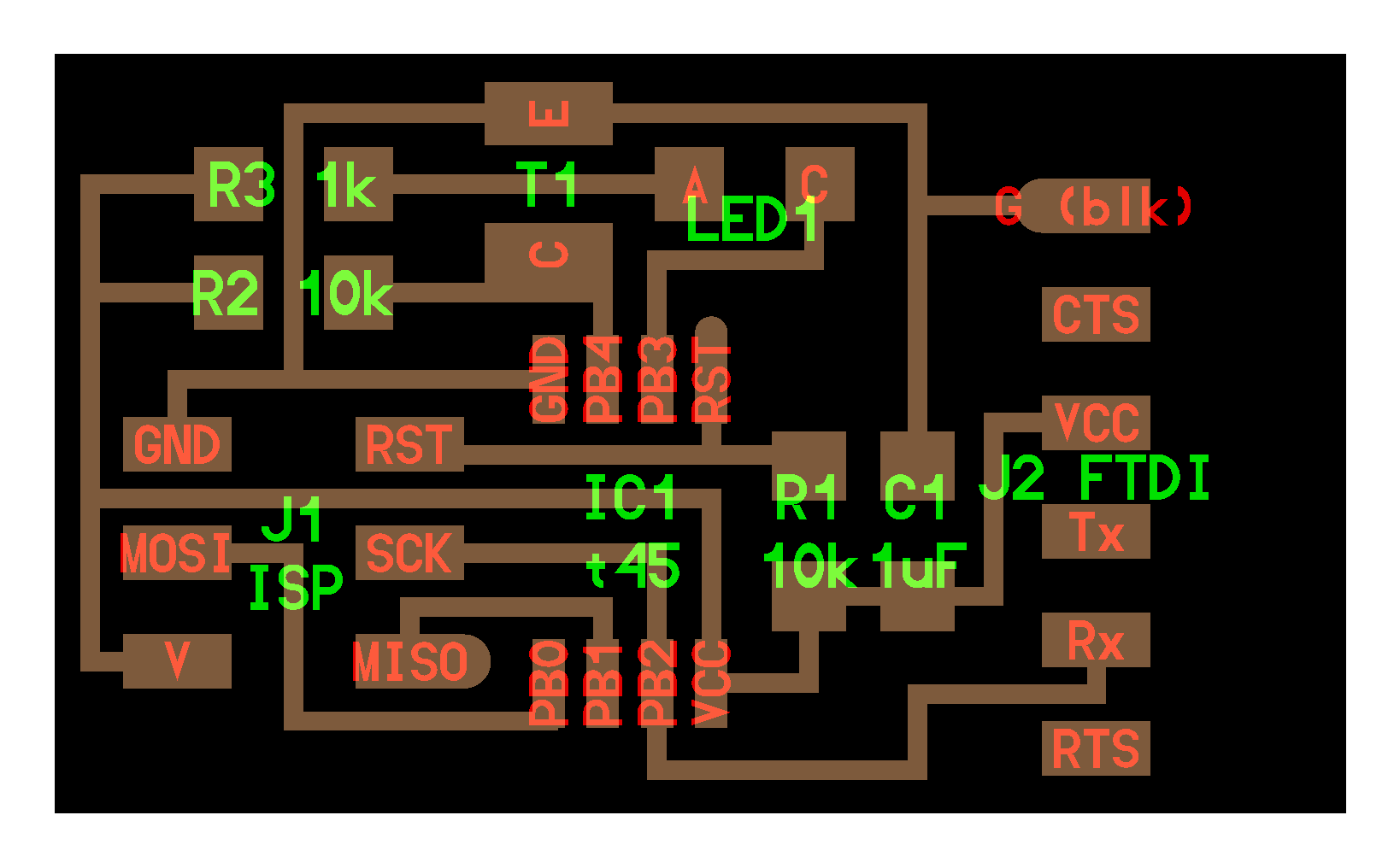
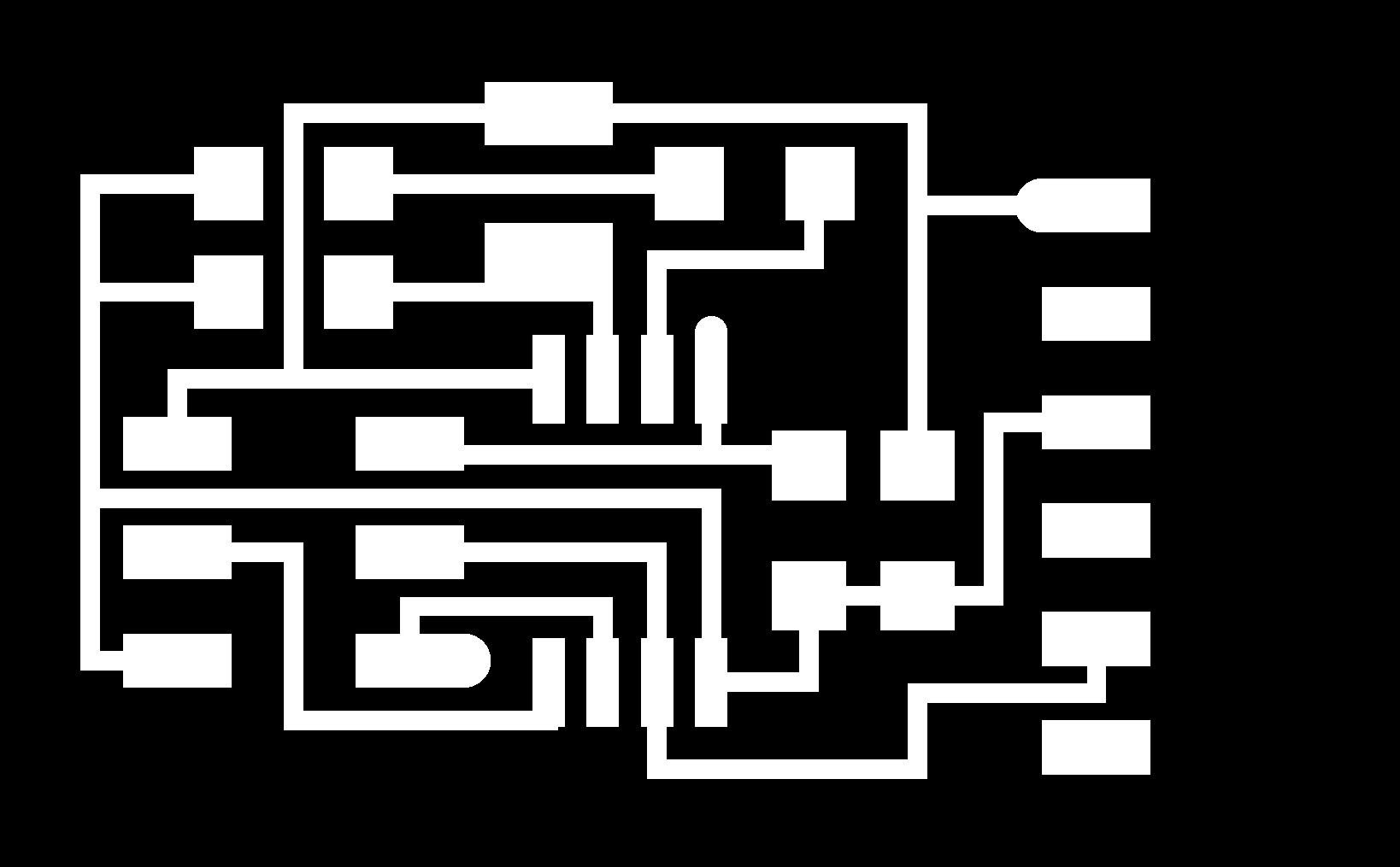
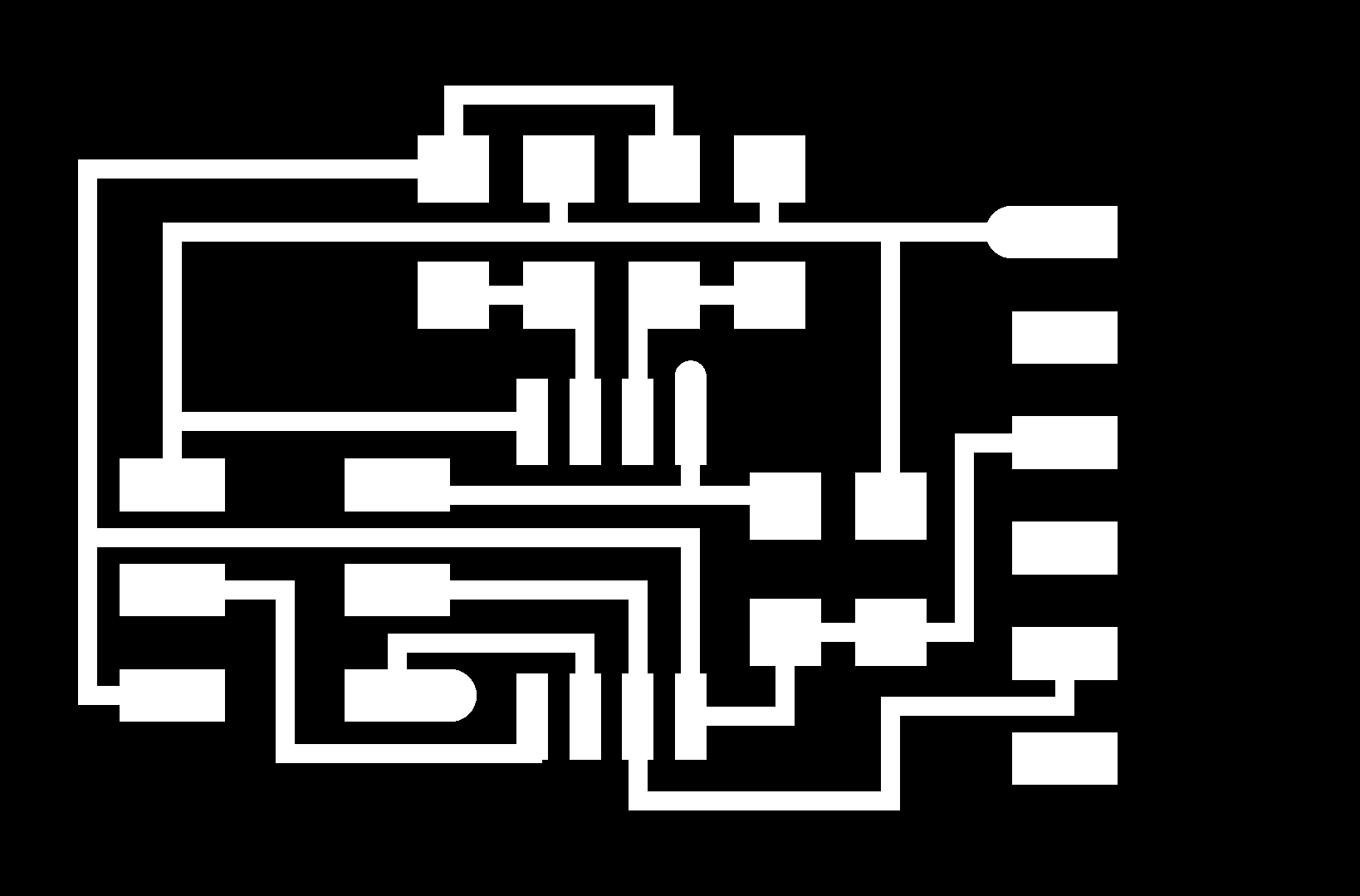
light sensor - synchronous detection
[board - traces - outline]
[x1 ATtiny45, x1 Resistor 10k, x1 Resistor 49,9k, x1 Resistor 1k, x1 Capacitor 1uf, x1 LED]
C file - Makefile - PY code
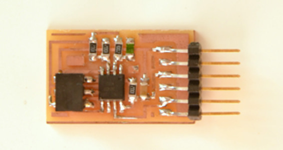
temperature sensor
[board - traces - outline]
[x1 ATtiny45, x4 Resistor 10k, x1 Capacitor 1uf, x1 Resistor NTC]
C code - Makefile - PY code

