Input devices
Hero shot
Group Assignments
I measure the analog output signal of my force sensor with an oscilloscope (see here).
I also usd a multimeter to measure the current drawn by my PCB.
Fabio also checks its sensor with an oscilloscope (see here).
Thrustmeter PCB
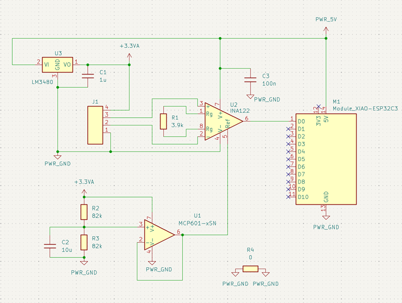
During Electronic design week, I designed a PCB to measure the Thrust of a water rocket.
I decided to mill this PCB with the Bantam PCB milling machine we have.
Fabio made a very good tutorial on how to use it during its Electronics production week.
Circuit udpates
Col
I made some updates on the PCB:
-
I look into the Fab lab inventory and didn't found the op-amp I used in my first design (I found it in the fabacademy library).
I select another one (MCP601) from my department's inventory.
For the same reason, I changed the instrumentation amplifier from INA818 to INA122.
-
I found easier and more reliable not to solder the Xiao directly on the PCB: it avoid short-circuit underneath it and facilitate its replacement.
I found that the fab lab library has a generic footprint designed to solder SMD headers/sockets for it.
Hence, I decided to use this footprint.
-
I removed the mounting holes. I plan to design an enclosure for the PCB and the force sensor.
The PCB will be held in place by the enclosure's design.
I look into the Fab lab inventory and didn't found the op-amp I used in my first design (I found it in the fabacademy library).
I select another one (MCP601) from my department's inventory.
For the same reason, I changed the instrumentation amplifier from INA818 to INA122.
I found easier and more reliable not to solder the Xiao directly on the PCB: it avoid short-circuit underneath it and facilitate its replacement.
I found that the fab lab library has a generic footprint designed to solder SMD headers/sockets for it.
Hence, I decided to use this footprint.
I removed the mounting holes. I plan to design an enclosure for the PCB and the force sensor.
The PCB will be held in place by the enclosure's design.
Col
Updated PCB
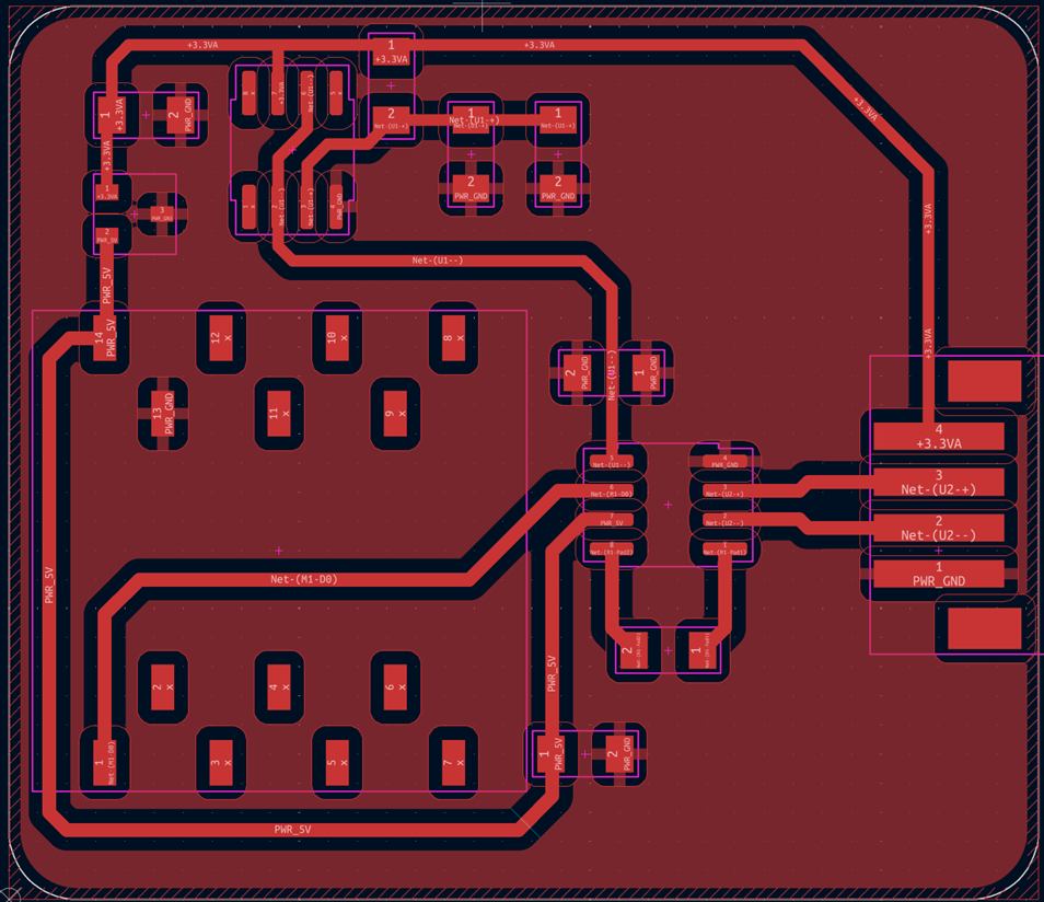
Here is the updated PCB design:
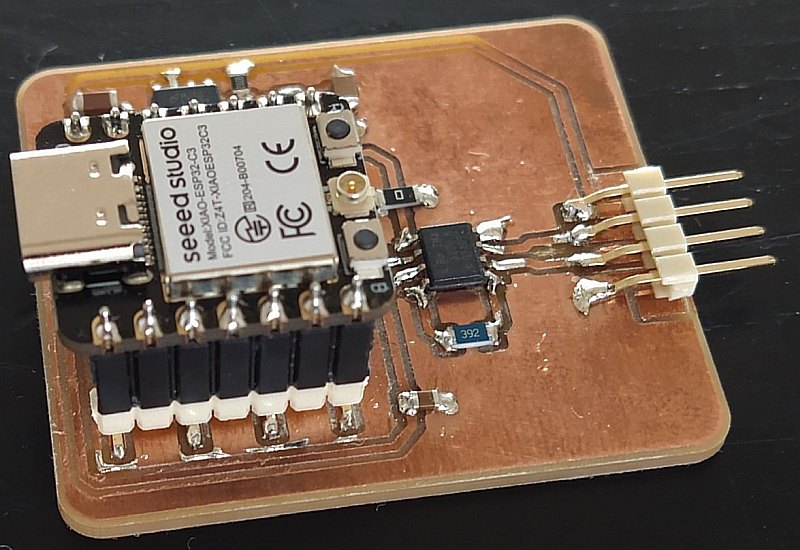
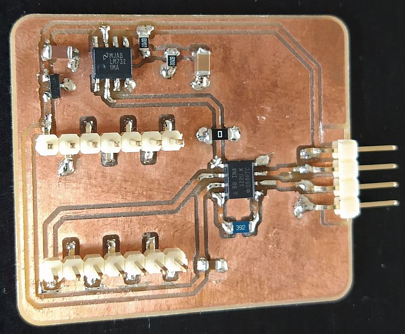
Here is the final result:
Col
Col
PCB testing
After the PCB milling, I sanded it to remove copper scraps.
Before soldering, I tested my PCB for short-circuits between copper traces.
I found none.
After soldering, I first powered the PCB with a lab power supply, using the Xiao 5V and GND pins.
I wanted to be sure that my PCB doesn't draw too much power. Its consumption was only a few mA, as expected.
Finally, I connected an oscilloscope to the Xiao analog input to check that the analog signal was correct: when I pressed on the sensor, the voltage should rise, as can be seen in the video.
ESP32 code
I wrote a simple code to test my circuit, using the Arduino IDE:
I connected the ESP32 to my PC and uploaded the code.
Next, I started the Serial Plotter to visualize the data streamed by the ESP32.
The values did not change when I pressed the sensor. In fact, a transient can be seen when the ESP32 reboots.
Afterwards, the value remains constant
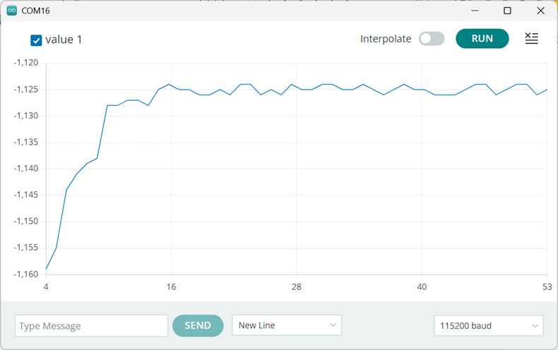
It makes me think that the ADC input is floating.
I search if there is something specific to do to use the EP32 ADC in Arduino.
I found that pin mapping must be used and that #define exists to map the pins correctly.
All I have to do is change line 12, replacing '0' by 'A0'.
Now the data are correctly acquired and streamed:
Better implementation
Here is a better implementation of the same code, using an hardware timer of the ESP32.
This timer triggers an interruption. The associated ISR (Interrupt Software Routine) execute the code previously in the loop() function.
The use of a timer interruption ensures a precise and constant sampling frequency.
hw_timer_t *timer = NULL;
volatile uint16_t data = 0;

// void IRAM_ATTR Timer0_ISR()
void ARDUINO_ISR_ATTR onTimer() {
  Serial.println( analogRead(A0) );
}

void setup() {
  Serial.begin(115200);
  timer = timerBegin(1000000);            // set timer frequency to 1Mhz
  timerAttachInterrupt(timer, &onTimer);  // attach onTimer function to the timer
  // Set alarm to call onTimer function every 20 ms (value in microseconds).
  // Repeat the alarm (third parameter) with unlimited count = 0 (fourth parameter).
  timerAlarm(timer, 20000, true, 0);
}

void loop() {
  // nothing to do here
}