System integration
Global structure
The sediment trap has to be transported by plane. Hence, I designed it in several parts to make it easier to fit into someone's luggage.
This modular design also helps the trap installation and the sediment samples retrieval.
- The main body (PVC tube) is permanently attached to a concrete base. This assembly is then placed on the desired underwater site. It'll stay there.
- The sediment collector (PMMA tube) is inserted in the main body. It's held in place by the adaptation part glued on the top of the main body.
- The funnel is then screwed in this adaptation part, securing the collector tube.
The funnel is itself an assembly:
- the bottom part has the thread to connect with the main body. It also act as a support for the intervalometer.
- Top and bottom parts are connected by a bayonet mount. They held the intervalometer in place.
- The entry grid is glued on the funnel's top part.
disc dispenser
The disc dispenser is, by far, the most complex part of my project.
I separated it in two parts:
- the electronics that drives the motor and has to be protected by a watertight enclosure
- the disc holder that is in direct contact with the water.
I choose to use a magnetic coupler to transfer mechanical power from the motor to the disc holder.
The huge advantage of this method is that it doesn't have any moving part that has to cross the watertight enclosure.
The other design steps are:
- I have to design a 3D structure that supports all the electronic components: motor, position sensor, batteries and PCB
- I decided to buy the watertight enclosure, as it has to stay for one year at a 50 m depth.
- It means that the structure has to fit in this enclosure.
- The disc dispenser also has to fit inside the funnel without getting in the way of the sediment
cable management
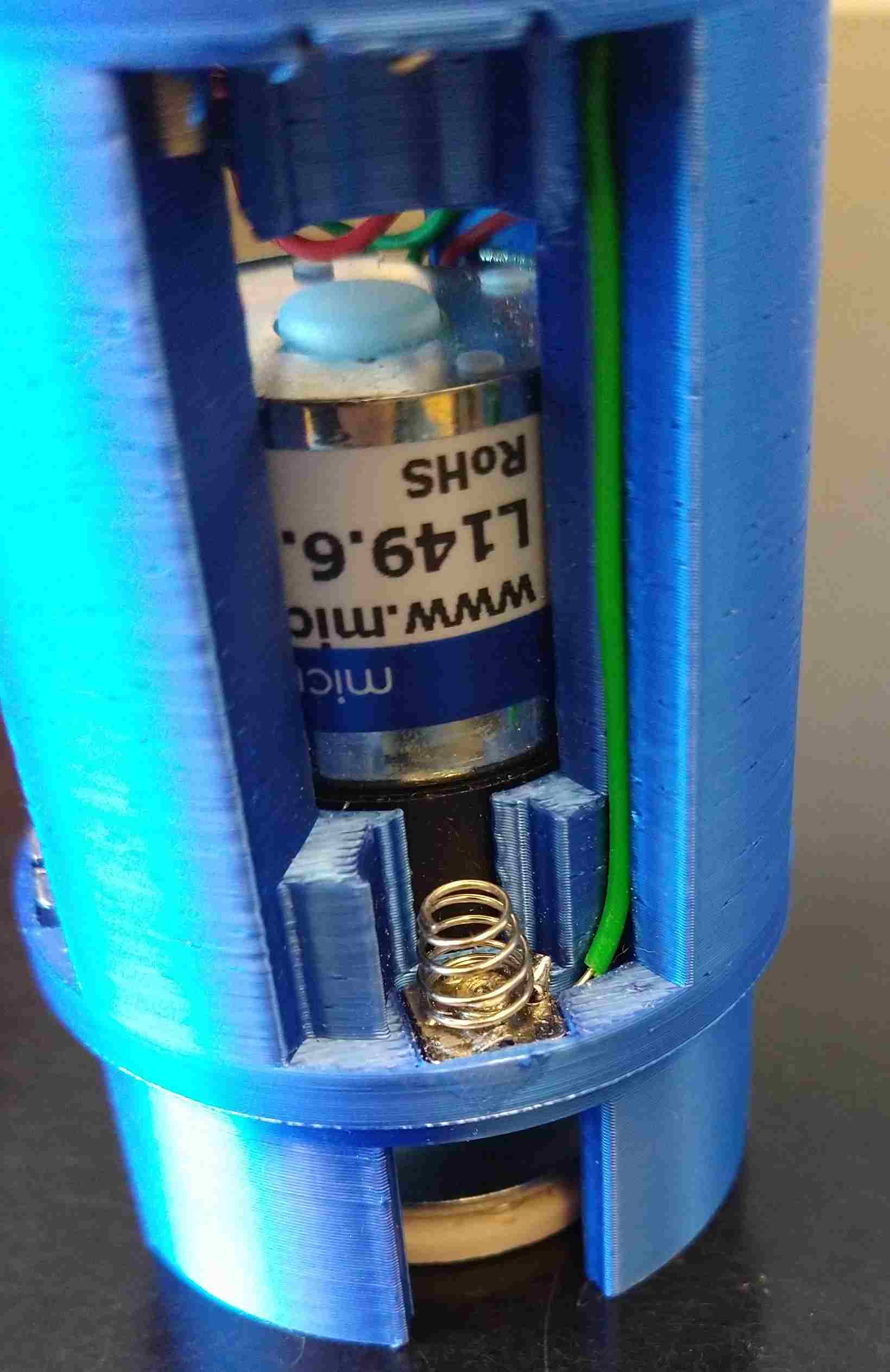
I pay special attention to the cable management in the disc dispenser.
I expect it to be vigorously shaken during plane transport (more precisely luggage handling at airports) and during its underwater installation.
To avoid any problem, I design the 3D structure to ensure that:
- batteries are stuck between the structure and the enclosure
- wires connecting the batteries goes through channels in the 3D structure and are single-core rigid cable
- the optical sensor is mounted on a dedicated PCB. This PCB is glued on the structure and also held in place by the assembly of the two parts of the structure
- the cable going from the sensor's PCB to the main PCB goes through a dedicated channel
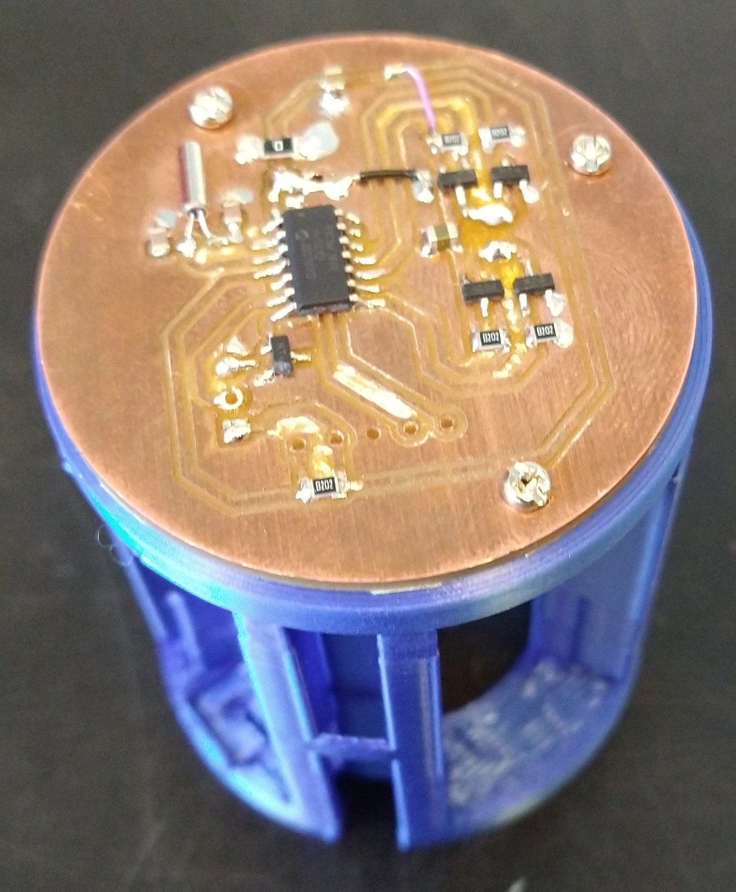
- the main PCB is screwed to the structure.
Col
Col

Col

Col
structure robustness improvement
In the first version of the disc dispenser, the structure was divided in three parts, glued together.
The aim was to make the assembly easier. It also makes the final result less robust: the two parts holding the batteries were mechanically stressed by their spring contacts. It tends to tear them apart.
Hence, I combined two parts in one with little added pain on the assembly (more detail on the disc dispenser page)
PCB
On the first prototype, I didn't pay attention on the connectors position on the PCB. I thought that, since I'll solder the wire directly on the PCB, it won't matter much. I would just have to design the structure around them.
The experience shows me that it would probably be easier the other way.
I managed to make room for the wires around the battery holder on the structure. However, it was a tight fit.
For the second version, I moved the components and the connectors to ease the assembly.
I also decided to use only one sensor, as I don't have to measure the rotation direction.
Finally, I made a dedicated PCB for the sensor, for robustness. It allows me to deport the associated resistor near the sensor, making room on the main PCB
On the first prototype, the PCB was glued on the structure. In the second version, I added holes to screw both together.
It helps positioning the PCB correctly on the structure.