Embedded programming
Summary
Part of my job is to teach embedded programming to bachelor students.
In my faculty, we mainly use PIC and PSoC microcontrollers (and some ESP32).
Hence, I decided to use this week assignments as an opportunity to discover the RP2040.
I wanted to try programming its PIO.
I decided to control a DC motor (with the RP2040 PWM peripheral) and measure its speed and position using a PIO.
Assignments
Group Assignment
This week, we program several microcontrollers with several toolchains.
Here is a summary of our respective works:
- Fabio and Michel programmed a RP2040 for their individual assignment.
Both used Thonny to write MicroPython code. Fabio used Aduino IDE and Michel used Microsoft VSCode to write C++ code. - Fabio has prior experience with the Arduino boards and IDE.
- Michel has prior experience with PIC microcontrollers from Microchip. He is a long time user of MPLAB X (Microchip IDE) and, more recently, the MPLAB X extension for VSCode.
- Jonas programmed a EPS32-S3. He used Thonny for MicroPython and Arduino IDE for C++.
individual assignment
- Browse through the data sheet for a microcontroller
- Write and test a program for an embedded system using a microcontroller to interact (with input &/or output devices) and communicate (with wired or wireless connections).
We often use mobile robots as support for embedded programming student projects.
These robots are driven by 2 DC motors, equipped with incremental encoders.
An incremental encoder is a position sensor, placed on the motor axis.
Some microcontrollers has a dedicated peripheral to interface with it. However, very few of them has two of these peripherals.
That means you have to handle the encoders (at least the second one) in software. That can use a lot of computation time, limiting the performances.
Hence, I decided to program one RP2040's PIO as an encoder interface.
MicroPython for RP2040
I never used MicroPython. Hence I start experimenting it on RP2040.
I followed Nicolas De Coster's documentation on how to start with MicroPhyton.
Simulations
Blink
I first simulate some small codes on Wokwi.
Of course, I started by blinking a LED, with Nicolas example.
PWM generation
Next, I read the MicroPython documentation.
The machine library contains functions to access and control the microcontroller hardware.
I look for the PWM functions. PWM stands for Pulse Width Modulation. It is used to control the speed of a DC motor.
I wrote a code to use it and tested it in simulation, based on the MicroPython wiki example:
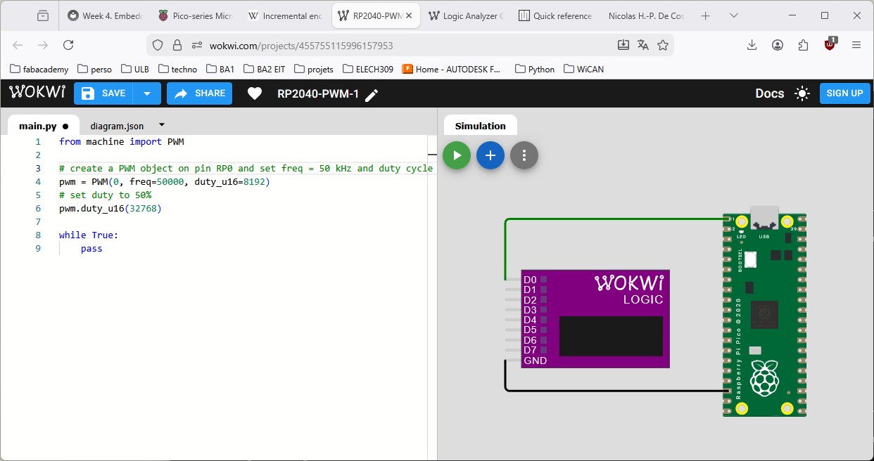
Code explanation:
- line 1 imports the PWM class from the machine library
- line 4 creates an instance (pwm) of PWM.
The constructor has 3 parameters: the first is the id of the pin to use as PWM output (RP0), the second is the PWM frequency and the last is its initial duty cycle. - line 6 changes the duty cycle to 50% (max duty cycle is 65535)
- lines 8 and 9 are an empty infinite loop.
The RP0 pin is connected to a logic analyzer.
When the simulation is run, the logic analyzer stores all changes on its inputs. When the simulation is stopped, a .vcd file is downloaded by the web browser.
This file contains the logic analyzer data. It can be visualized with pulseView, an open-source GUI for logic analyzers.
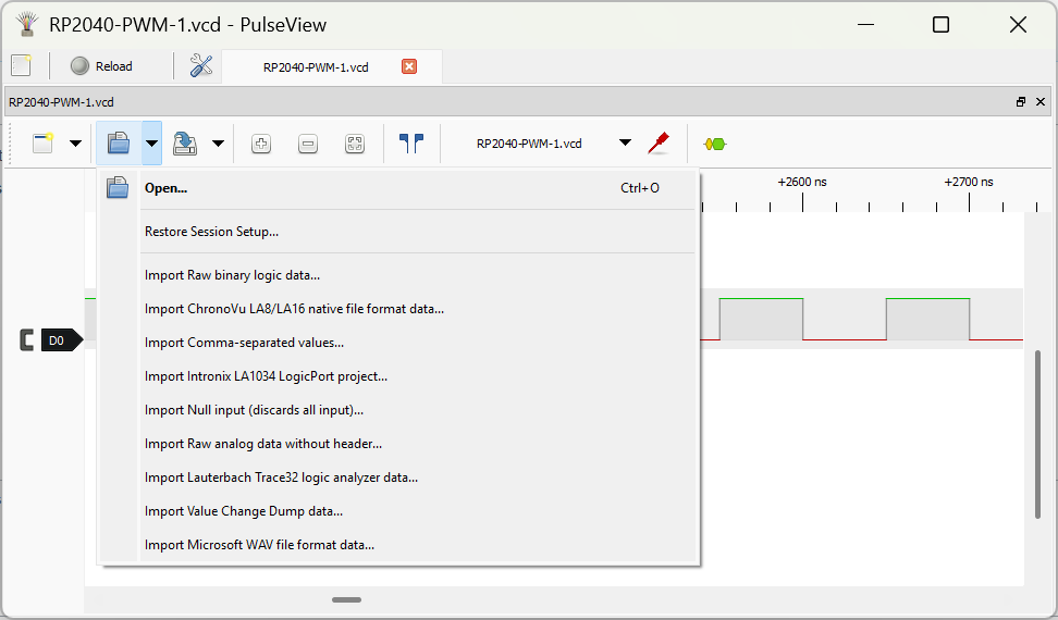
In the Open menu of PulseView, choose Import Value Change Dump data... to visualize the downloaded file.
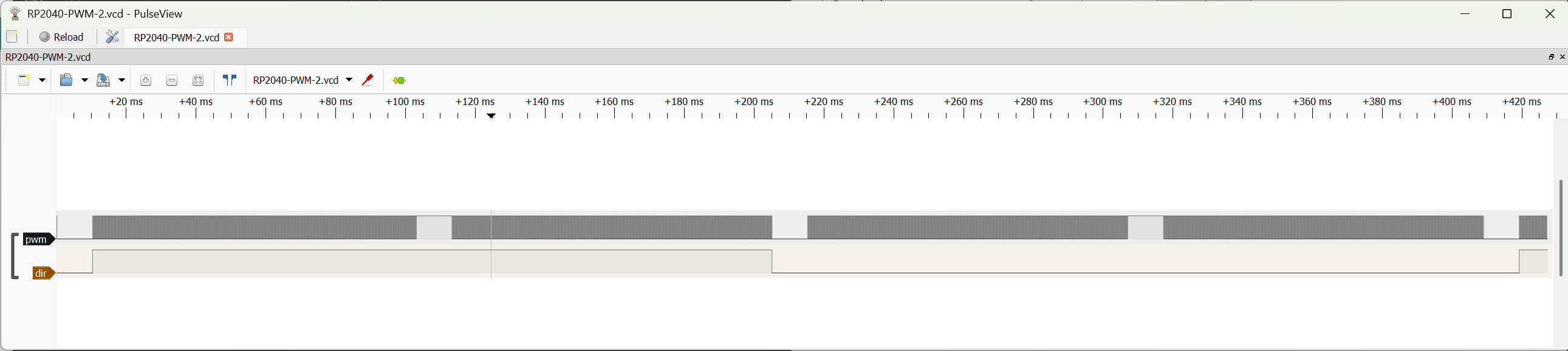
I modified my code to change the duty cycle over time:
from machine import PWM, Pin
import time

# Creates pwm and dir signals to drive a DRI0044 motor driver
# Starting from 0, the motor speed is incremented to its max value, turning clockwise
# Then it decelerates to 0.
# It does the same counter-clockwise, then starts all over again

# create a PWM on GP0 with freq = 50 kHz and duty cycle = 0%
pwm = PWM(0, freq=50000, duty_u16=0)
# set GP1 as an general purpose output
dir = Pin(1, Pin.OUT)

# pwm duty cycle sets the motor speed, dir state sets the motor direction (0=CW or 1=CCW)
# This code is to use with a DRI0044 motor driver

def motor_set_speed(dc):
    """ set the motor duty cycle.
        parameter: dc is a float in [-1, 1] range.
        the motor turns clockwise for positive dc values
        and counter-clockwise for negative dc values """
    if dc < 0:
        dir.on();
        dc = -dc
    else:
        dir.off()
    if dc > 1:
        dc = 1
    pwm.duty_u16(int(dc*65535)) # duty_16 needs and unsigned 16-bit integer

dc = 0      # initial duty cycle, in per unit
incr = 0.1  # duty cycle increment

while True:
    dc = dc + incr
    if (dc >= 1) or (dc <=-1):
        incr = -incr
    motor_set_speed(dc)
    time.sleep(0.01)
Wokwi simulation: https://wokwi.com/projects/455756396006852609
Logic analyzer data: RP2040-PWM-2.vcd Using PulseView, we obtain:
Test on a Raspberry Pi Pico 1 board
Next, I wanted to test my last code on a RP2040 board.
First step is to install Thonny, a Python IDE.
I followed the instructions on Nicolas'page
I ran his "Hello World" without any problem
Hence, I copy my PWM code in Thonny and run it.
Again, no problem. I visualize both signals with a logic analyzer:

C/C++ SDK for RP2040
I also wanted to try the C/C++ SDK for the RP2040.
Installation
I followed the installation procedure described in Getting started with Raspberry Pi Pico
Visual studio Code was already installed on my computer. Hence, I just needed to install the Raspberry Pi Pico code extension
To test the toolchain, I created a new project from the blink example:
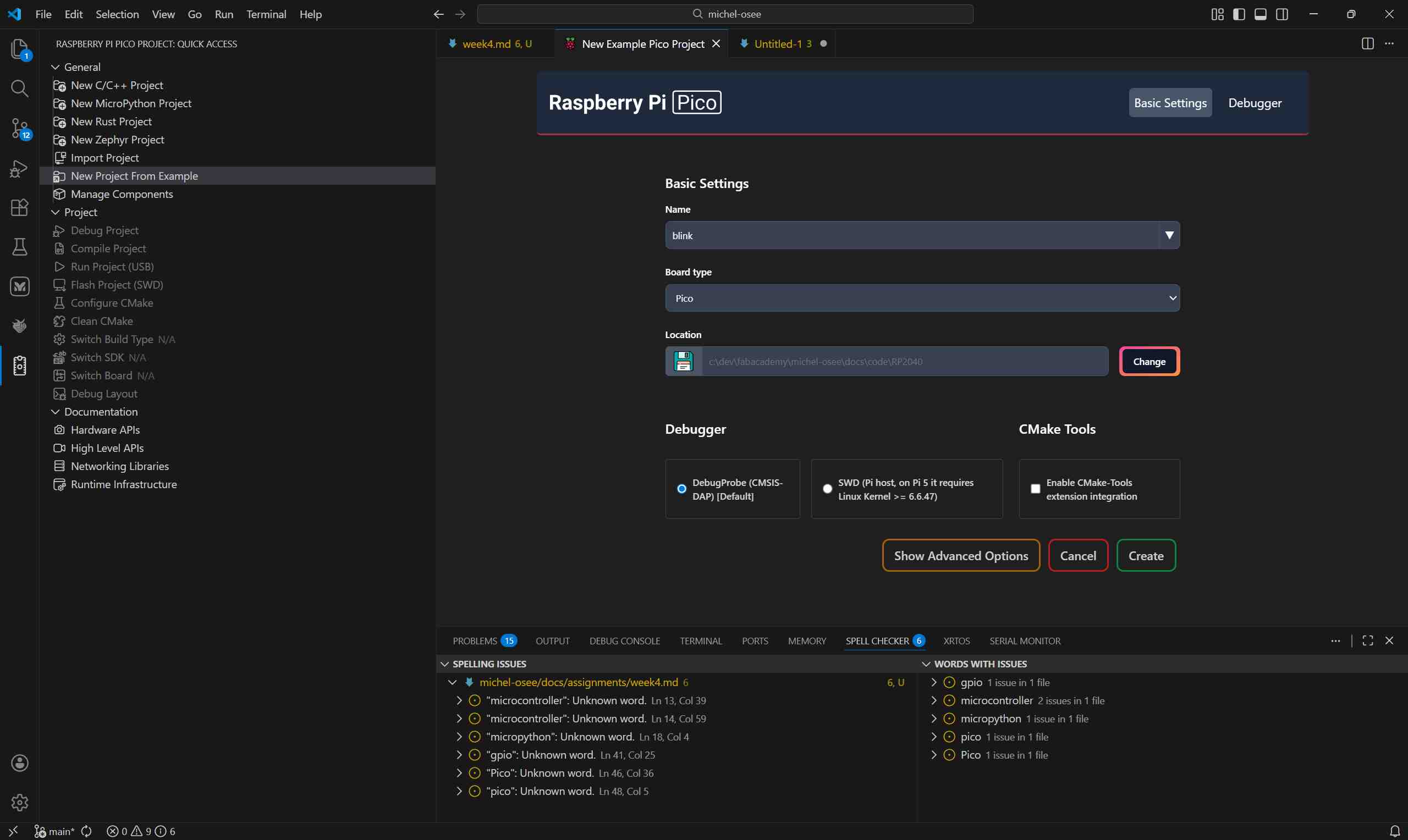
As it was the first project created for this code extension, it automatically installed and configure the needed tools.
Hello World
Next, I tried to run the project.
It failed with this error message: "No accessible RP-series in BOOTSEL mode were found".
After a quick search, I found the solution: the RP2040 needs to be booted with the BOOTSEL button pressed.
That means that, each time you want to program it, you need to unplug its USB cable, then re-plug it with the BOOTSEL button pressed.
Using this method, I was able to run the "Hello World".
PIO module
I wanted to try programming a PIO module. Hence, I created a new project:
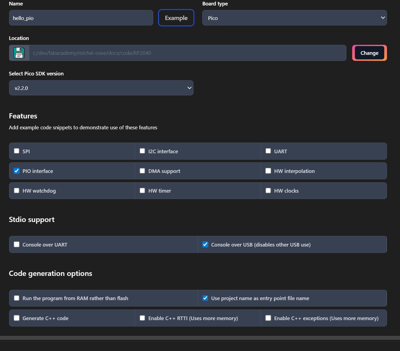
In the creation options:
- I selected the "Board type" as Pico (I have a PICO 1 board)
- I checked the PIO interface feature
- I also checked Console over USB in Stdio support. This last feature tells the RP2040 to send the printf messages over the USB connexion. These messages can be seen directly in VSCode (in the serial monitor).
The SDK created me a complete project, with a nice example code, using a PIO state machine to blink the on-board LED. It also send "Hello World!" to the serial monitor.
PIO overview
I started to read the PIO chapter of the RP2040 datasheet.
The RP2040 has two PIO modules. Both modules contains four State Machines.
A PIO state machine is a small CPU with a specific architecture designed to implement custom hardware interfaces. It has only 9 assembly instructions and four registers.
The datasheet contains this figure (pg. 306), detailing the architecture of a PIO module:
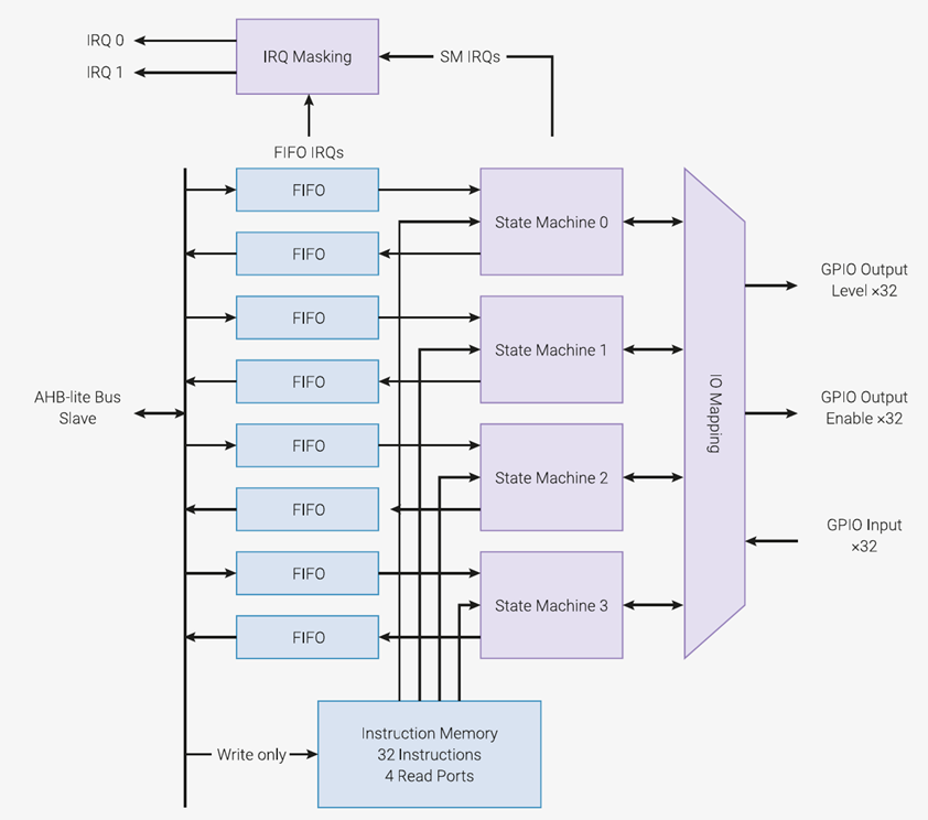
We can see that:
- the state machines share a unique instruction memory. They have separate data paths, allowing them to access the memory simultaneously. This memory can contain 32 instructions.
That means that the state machines can execute code at the same time. They can execute the same program or different ones. The only constraint is that the total length of all programs could not be greater than 32 instructions. - The state machines are connected to the GPIO pins through a IO mapping block. this block can connect the desired GPIO pin(s) to a state machine, as an input or an output.
A state machine can control any GPIO. Hence, the programmer has complete freedom on the pin mapping. - each state machine has 2 FIFO (First In, First Out) buffer to exchange data with the main CPU.
The Tx FIFO transmit data from the CPU to the state machine.
The Rx FIFO transmit data from the state machine to the CPU.
A DMA channel can be used to handle these data exchanges. - Both FIFOs and state machines can raise IRQ flags to trigger the main CPU.
On the next page, we found a figure describing the state machine architecture:
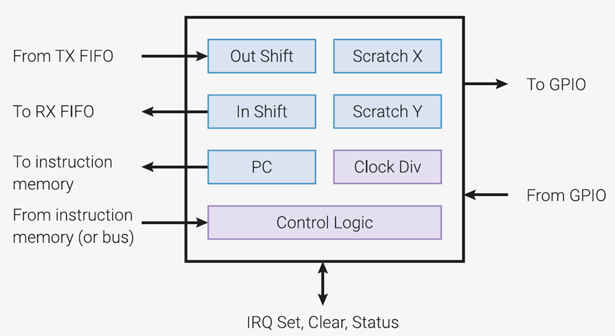
The blue blocks are the internal 32-bit registers:
- Scratch X and Scratch Y are general purpose registers. they are also referred as X and Y.
- Out Shift receives the data coming from the Tx FIFO. It's also referred as ISR
- Data to send to the Rx FIFO must be written in In Shift. It's also referred as OSR
- Both Shift registers can also be used as general purpose registers.
- PC is the Program Counter. It contains the address of the next instructions to execute.
The purple blocks are :
- Control Logic is where the magic is done: it reads an instruction in memory, decodes and execute it.
- Clock Div determines the instruction frequency, by dividing the main CPU clock frequency.
PIO instruction set
General structure
The PIO state machines have only nine 16-bit instructions, summarized in this table:
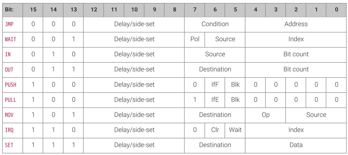
- Bits 15-13 are the instruction identifier
- Bits 12-8 contains either a delay or a Side-set (see below)
- The other bits' purpose depends on the instruction.
All instructions are executed in one clock cycle.
The instructions are quickly described in the rest of this section. A more detailed descriptions can be found in the datasheet.
I detailed how I use them in the programs I wrote in the following sections.
Delay/side-set
The Delay/side-set field is present in all instructions.
When initializing te state machine, the main code can assign up to 5 pins as side-set pins.
The state machine can change their level as a "side effect" of any instruction. It happens concurrently with the instruction's execution and cost no additional time.
The side-set pins' new state are encoded in the delay/side-set field of the instruction.
If less than 5 side-set pins are defined, the remaining bits of delay/side-set field (up to 5) can be used to encode the number of idle cycles to insert between this instruction and the next.
In most instruction sets, a NOP instruction exists to create delays.
With these two mechanisms, one instruction can perform multiple operations.
This allow to write compact code, in order to mitigate the (very) small PIO module's memory.
JMP
Most of the time, the instructions are executed sequentially. When the program's end is reached, the state machine loops back to its beginning.
JMP allows to choose the next instruction to execute. The address in the instruction (bits 4-0) contains the address of the next instruction.
The jump can be unconditional or conditional. The condition is defined by the condition field.
The conditions are:
- Scratch X (or Scratch Y) are equal to zero
- Scratch X (or Scratch Y) is first decremented, then the jump occurs if its new value is not zero.
This is the first example of an instruction with multiple actions (decrement a register and execute a jump). - Scratch X is not equal to Scratch Y
- a GPIO pin state is high. It allows to react the an input pin change.
- Out Shift is not empty: if Out Shift is used to send serial data to a GPIO, it allows to know when all bits are sent.
WAIT
This instruction blocks the execution of the code until a condition is met.
The condition to met is defined by the source field. The condition are:
- wait for a GPIO state: the GPIO number is defined by the index field (this is the GPIO number in the pinout of the RP2040).
The awaited state (1 or 0) is defined by the Pol bit. - wait for a pin state: this is the same as the previous one. The only difference is that the index field refers to the GPIO pin through the IO mapping of the state machine. It's a relative reference that depends on the pin associated to the state machine during its configuration in the main (C++ or microPython) code.
- wait for a IRQ flag state: the IRQ number is defined by the index field and the awaited state (1 or 0) is defined by the Pol bit.
IN
This instruction shifts Bit count bits from Source into the In Shift register.
The source can be: pin(s), scratch X, Scratch Y, In Shift or Out shift. It's also possible to shift zeros (to reset its content).
OUT
This instruction shifts Bit count bits to Destination from the Out Shift register.
The destination can be: pin(s), scratch X, Scratch Y or In Shift.
Bits can also be shifted to "nowhere" to discard them.
There are three other destinations:
- pindirs: it allows to change the direction of the pins (input or output)
- PC: it allows to trigger a jump in the code from the main CPU code, by sending the desired address in the Tx FIFO
- EXEC: it shifts 16 bits of Out Shift to the instruction register. Hence, it's executed as an instruction directly sent by the main CPU code.
These last two options looks powerful and dangerous to use.
PUSH
this instruction pushes the contents of ISR into the Rx FIFO, as a single 32-bit word. Clear ISR to all-zeros.
If IfF (If Full) bit is set, the instruction do nothing unless ISR is full. The "full" threshold can be defined when the state machine is initialized.
If Blk (Block) bit is set, the instruction waits until the Rx FIFO has space to accept the data.
PULL
This instruction loads a 32-bit word from the Tx FIFO into OSR.
If IfE (Is Empty) is set, the instruction do nothing unless there is enough bits to read in the Tx FIFO. This number can be defined when the state machine is initialized.
If Blk (Block) bit is set, the instruction waits until the Tx FIFO contains enough bits to read.
If BLK is zero, and the Tx FIFO is empty, X content is copied in OSR.
MOV
This instruction copies data from the Source to the Destination.
The Source can be:
- the pins associated to the state machine
- X, Y, ISR or OSR
- STATUS (it's a register reflecting the internal status of the state machine)
- NULL, that'll fill the Destination with zeros
The Destination can be:
- the pins associated to the state machine
- X, Y, ISR or OSR. ISR and OSR are reset to zero
- PC. This is equivalent to an unconditional JUMP
- EXEC. This has the same behavior as the OUT equivalent
Optionally, an operation can be performed on the destination data:
- Invert (the bit-wise complement)
- Bit-reverse: the bit order is reversed.
IRQ
This instruction raises or clears the IRQ flag given by the Index field.
If Clr and Wait are '0', the instruction raises the flag.
If Clr (clear) bit is '1'', the instruction clears the flag and the Wait bit has no effect.
If Wait is '1' (and Clr is '0'), the instruction waits for the flag to be cleared (by another state machine or the main CPU)
SET
This instruction writes Data value to the Destination.
The Destination can be:
- the pins associated to the state machine
- X or Y, Data is written on the 5 lsb (least significant bits). The other bits are set to zero
- pindirs: it allows to change the direction of the pins (input or output).
Quadrature encoder PIO interface
Now that I have an idea of the PIO architecture and its instruction set, I have to think about how to use it to read an encoder's signals.
Obviously, I first search for an existing implementation. I found one in the pico-examples Github repository.
However, the easiest way to get it is to use the create a project from an example feature of the SDK:
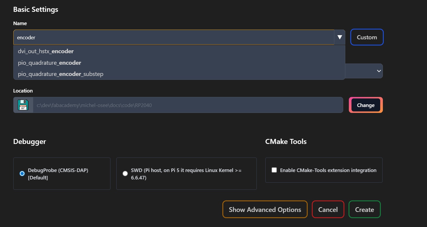
I first tried the pio_quadrature_encoder example.
A zip file of the project's folder is linked in the useful files section.
The main code (quadrature_encoder.c) configures a PIO module and one of its state machine to execute the PIO code (quadrature_encoder.pio).
PIO code
The PIO code examples are already well documented. I had no difficulty to understand its structure, even if it's a bit tricky, in order to minimize the code size.
.program quadrature_encoder

; the code must be loaded at address 0, because it uses computed jumps
.origin 0


; the code works by running a loop that continuously shifts the 2 phase pins into
; ISR and looks at the lower 4 bits to do a computed jump to an instruction that
; does the proper "do nothing" | "increment" | "decrement" action for that pin
; state change (or no change)

; ISR holds the last state of the 2 pins during most of the code. The Y register
; keeps the current encoder count and is incremented / decremented according to
; the steps sampled

; the program keeps trying to write the current count to the RX FIFO without
; blocking. To read the current count, the user code must drain the FIFO first
; and wait for a fresh sample (takes ~4 SM cycles on average). The worst case
; sampling loop takes 10 cycles, so this program is able to read step rates up
; to sysclk / 10  (e.g., sysclk 125MHz, max step rate = 12.5 Msteps/sec)

; 00 state
    JMP update    ; read 00
    JMP decrement ; read 01
    JMP increment ; read 10
    JMP update    ; read 11

; 01 state
    JMP increment ; read 00
    JMP update    ; read 01
    JMP update    ; read 10
    JMP decrement ; read 11

; 10 state
    JMP decrement ; read 00
    JMP update    ; read 01
    JMP update    ; read 10
    JMP increment ; read 11

; to reduce code size, the last 2 states are implemented in place and become the
; target for the other jumps

; 11 state
    JMP update    ; read 00
    JMP increment ; read 01
decrement:
    ; note: the target of this instruction must be the next address, so that
    ; the effect of the instruction does not depend on the value of Y. The
    ; same is true for the "JMP X--" below. Basically "JMP Y--, <next addr>"
    ; is just a pure "decrement Y" instruction, with no other side effects
    JMP Y--, update ; read 10

    ; this is where the main loop starts
.wrap_target
update:
    MOV ISR, Y      ; read 11
    PUSH noblock

sample_pins:
    ; we shift into ISR the last state of the 2 input pins (now in OSR) and
    ; the new state of the 2 pins, thus producing the 4 bit target for the
    ; computed jump into the correct action for this state. Both the PUSH
    ; above and the OUT below zero out the other bits in ISR
    OUT ISR, 2
    IN PINS, 2

    ; save the state in the OSR, so that we can use ISR for other purposes
    MOV OSR, ISR
    ; jump to the correct state machine action
    MOV PC, ISR

    ; the PIO does not have a increment instruction, so to do that we do a
    ; negate, decrement, negate sequence
increment:
    MOV Y, ~Y
    JMP Y--, increment_cont
increment_cont:
    MOV Y, ~Y
.wrap    ; the .wrap here avoids one jump instruction and saves a cycle too
Main code
Here are the configuration code for the state machine:
    PIO pio = pio0;
    const uint sm = 0;
    const uint PIN_AB = 10;

    pio_add_program(pio, &quadrature_encoder_program);
    quadrature_encoder_program_init(pio, sm, PIN_AB, 0);
- First a PIO object (
pio) is created and defined to the PIO 0 module smdefines which state machine to use (0 -> 3)PIN_ABdefines the GPIO pin connected to the encoder's channel A. Channel B must be connected to the following one (11).pio_add_programassigns the PIO code (found in the .pio file) to the PIO module memoryquadrature_encoder_program_initis defined in the pio file, as it's related to the pio code
static inline void quadrature_encoder_program_init(PIO pio, uint sm, uint pin, int max_step_rate) {
    pio_sm_set_consecutive_pindirs(pio, sm, pin, 2, false);  // sets both encoder's pins as inputs
    pio_gpio_init(pio, pin);        // these 2 lines select the pio as the peripheral connected
    pio_gpio_init(pio, pin + 1);    // to the encoder's pins

    gpio_pull_up(pin);      // These 2 lines activates the pull-up resistors
    gpio_pull_up(pin + 1);  // for the encoder's pins

    // this function is automatically generated by the SDK to create a default config for your state machine
    // based on your pio code
    pio_sm_config c = quadrature_encoder_program_get_default_config(0);

    sm_config_set_in_pins(&c, pin); // defines the pins for WAIT, IN instructions
    sm_config_set_jmp_pin(&c, pin); // defines the pins for JMP
    // defines the shift registers behavior: shift to left, autopull disabled
    sm_config_set_in_shift(&c, false, false, 32);
    /* Both TX and RX FIFO's can be joined to create a single one (twice as long).
     * However, it means that data can be sent in only one direction.
     * In our case, we don't need FIFO as we only want the latest value
     * -> we don't join them */
    sm_config_set_fifo_join(&c, PIO_FIFO_JOIN_NONE);

    // sets the sate machine cycle frequency
    if (max_step_rate == 0) {   // passing "0" as the sample frequency, if max rate is desired
        sm_config_set_clkdiv(&c, 1.0);
    } else {
        // one state machine loop takes at most 10 cycles
        float div = (float)clock_get_hz(clk_sys) / (10 * max_step_rate);
        sm_config_set_clkdiv(&c, div);
    }

    pio_sm_init(pio, sm, 0, &c);        // init the state machine
    pio_sm_set_enabled(pio, sm, true);  // enable the state machine
}
A second C++ function is defined in the pio file. Its purpose is to read the position measured by the encoder:
static inline int32_t quadrature_encoder_get_count(PIO pio, uint sm)
{
    uint ret;
    int n;

    // if the FIFO has N entries, we fetch them to drain the FIFO,
    // plus one entry which will be guaranteed to not be stale
    n = pio_sm_get_rx_fifo_level(pio, sm) + 1;
    while (n > 0) {
        ret = pio_sm_get_blocking(pio, sm);
        n--;
    }
    return ret;
}
The pio code tries to write every new position in the RX FIFO. If the latter is full, nothing happens (the measured position is always up-to-date in Y).
To get the current position, quadrature_encoder_get_count reads n + 1 values in the FIFO, where n is the FIFO size.
The n first values are the content of the FIFO and are outdated. The final one must be a new one.
The main loop samples the encoder's position by calling quadrature_encoder_get_count every 100 ms.
I the measured position has changed, it uses printf to send it on the serial port.
    while (1) {
        // note: thanks to two's complement arithmetic delta will always
        // be correct even when new_value wraps around MAXINT / MININT
        new_value = quadrature_encoder_get_count(pio, sm);
        delta = new_value - old_value;
        old_value = new_value;

        if (new_value != last_value || delta != last_delta ) {
            printf("position %8d, delta %6d\n", new_value, delta);
            last_value = new_value;
            last_delta = delta;
        }
        sleep_ms(100);
    }
I used a simple circuit to test the code:
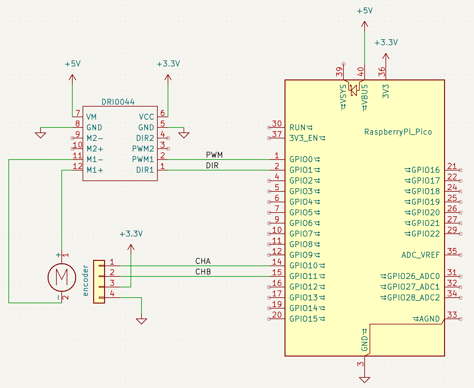
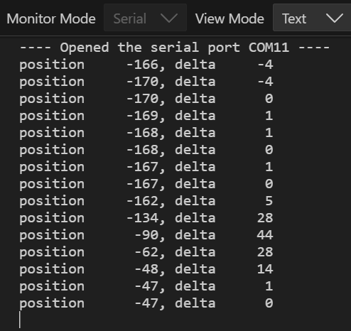
As a first test, I did not connect the motor to the driver and turn its axis by hand to feed the encoder.
I connected a serial monitor to the RP2040 serial port and obtain data showing that the code works as intended:
Adding the PWM
Next step id to add the PWM control for my motor:
I added these code lines to the configuration code:
    #define DIR_PIN 1
    #define PWM_PIN 0

    // set DIR pin as a GPIO output, with initial state at 0
    gpio_init(DIR_PIN);
    gpio_set_dir(DIR_PIN, GPIO_OUT);
    gpio_put(DIR_PIN, 0);

    // configure PWM pin as a PWM output
    gpio_set_function(PWM_PIN, GPIO_FUNC_PWM);
    // Find out which PWM slice is connected to GPIO 0 (it's slice 0)
    slice_num = pwm_gpio_to_slice_num(0);
    // Set period of 2500 cycles <=> 50kHz
    pwm_set_wrap(slice_num, 2499);
    // Set duty cycle at 0
    pwm_set_chan_level(slice_num, PWM_CHAN_A, 0);
    // Set the PWM running
    pwm_set_enabled(slice_num, true);
The SDK comes with a PWM library and I got inspiration from their PWM example.
My current experience of the SDK is that reading the example code related to a peripheral is almost enough to understand how to use it (however, I may be helped by my knowledge of other microcontroller families).
In this case, I just had to check what's a "slice": the PWM peripheral is composed of 8 identical slices. Each GPIO is connected to one slice's PWM output.
Hence, ths SDK provides a function to easily get the slice associated to a given GPIO: pwm_gpio_to_slice_num.
Finally, I added a function to change the motor's speed and direction:
/* Sets the motor speed and direction
 * Parameter:
 *   - dc:  PWM duty cycle. Range: [-1, 1]
 *          its sign sets the direction
 *          its absolute value sets the speed:
 *            - |dc| = 0 <=> speed = 0
 *            - |dc| = 1 <=> max speed          */
void motor_set_speed(float dc) {
    if (dc < 0) {
        gpio_put(DIR_PIN, 1);   // set the reverse direction
        dc = -dc;               // dc absolute value
    } else {
        gpio_put(DIR_PIN, 0);   // set the forward direction
    }
    if (dc > 1) {
        dc = 1;     // saturates the dc
    }
    pwm_set_chan_level(slice_num, PWM_CHAN_A, (uint16_t)(2500*dc));
}
I had an error when I tried to compile my code: the compiler couldn't find the pwm.h file.
I had to manually add it in the CMakeLists.txt file:
target_link_libraries(pio_quadrature_encoder PRIVATE
        pico_stdlib
        pico_multicore
        hardware_pio
        hardware_gpio
        hardware_pwm
        )
I was then able to run the code.
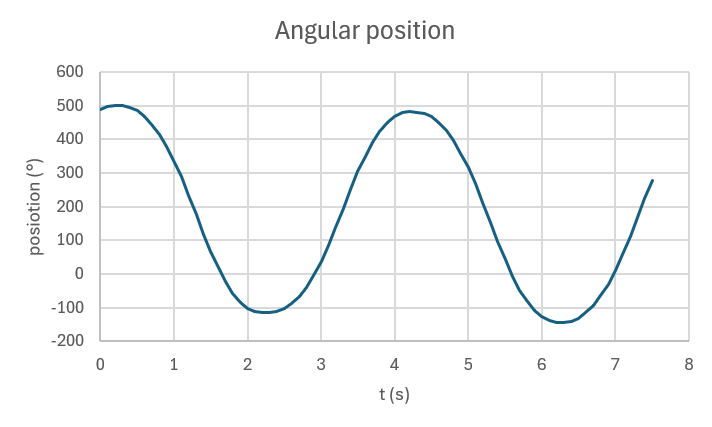
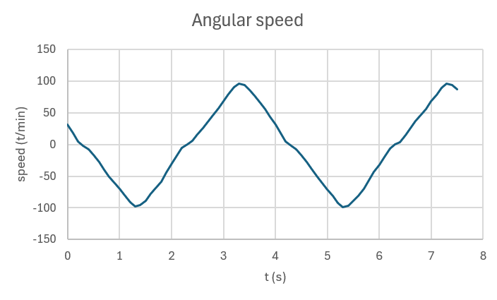
As it sends the encoder's position and speed on the serial monitor, I saved the data received in the serial monitor in a csv file.
I imported it in Excel to plot boh positon and speed:
What I learned this week
- MicroPython programming (for RP2040)
- RP2040 global architecture and its PIO programming
- C/C++ SDK for raspberry pico 1