The disc dispenser
Roadmap
- Requirements definition
- Marker definition
- Mechanism choice
- Components choice
- Design
- Energy budget study
Requirements
We had a brainstorming with Alexia to choose the type of markers to use.
They need to show a chronological separation between sediment layers.
Hence, the main concern is to avoid their migration inside the sediment deposit.
The sediment is basically mud. It means that objects can easily move inside.
We list different possibilities:
- a simple disk
- an "hydrodynamic" disk
- a layer of small beads or colored sand
Simple disk solution
In the literature, solutions with simple disks already exists.
A disk has a large contact surface. It ensures that the pressure on the sediment due to its weight is moderate.
If its diameter is close to the tube's one, the sediment won't have much space to move around the disk.
That'll help prevent the disk to move inside the tube.
Our main concern is about how it will fall inside the tube.
More precisely, it has to fall "horizontally" to land smoothly on the sediment.
If it falls vertically, it loses the advantage described above.
"Hydrodynamic" disk
An improvement for the previous solution is to use a marker that has a large contact surface, but a more hydrodynamic shape.
Our first idea is a flat cone. Flat, because we also have a space constraint: the disk dispenser has to fit inside the funnel.
Beads layer
Another idea we had is to drop a given quantity of small glass bead (or something similar like sand).
The motivation would be that it will create a separation layer between two sediment layers.
One advantage would be that it'll follow the sediment shape (the sediment top surface is usually not flat nor horizontal).
We rejected this solution because we fear that these beads could easily move inside the sediment, if their densities don't match.
Marker choice
We decided to go for a disk-like marker.
As it's easy to 3D-print, we'll try different shapes.
Mechanical design
I'll study two disk dispenser structures.
Threaded rod mechanism
Col
The first is inspired by the Archimedes' screw.
- The disks have a threaded hole in their center
- They are mounted on a threaded rod (our screw)
- This assembly is placed in a tube
- A rail on the tube's inside face will prevent the disk to rotate
- Hence, the screw rotation will make the disk go up or down inside the tube
I modelled a first draft of the disk dispenser as part of the Computer-Aided Design assignment.
Col

Rotating slot mechanism
This design concept is used by many distribution mechanism (for example, Corey Rice's final project).
- The object to distribute are placed in a container
- A moving part allows an object to exit the container. Its shape and movement ensures that only one object can exit during its movement. Usually, it keep it in a transfer cavity.
- It transports the object to the mechanism exit.
Col
I ended up with this sketch. I made it with Microsoft Paint, as part of the CAD week assignment.
It shows the dispense from the side and from above.
- The disks, in blue, are stacked in a tube.
- The green plate is the bottom of the dispenser. It has an opening from which the disks will be dropped.
- The spacing between the tube bottom and the plate is a bit greater than the disks' thickness.
Hence,the bottom disk prevents the others to move.
- A "finger", in brown, is actuated by a motor, in orange.
It can push on the side of the bottom disk above the output to be dropped.
During it's movement, it is in the way of the other disks, preventing them to move.
When it comes back to its resting position, a new disk replaced the dropped one.
Hence,the bottom disk prevents the others to move.
It can push on the side of the bottom disk above the output to be dropped.
During it's movement, it is in the way of the other disks, preventing them to move.
When it comes back to its resting position, a new disk replaced the dropped one.
Col

Mechanism choice
We decided to go for the threaded rod mechanism
- The needed torque will be lower as it only need to overcome the frictions on the rod and the rail.
On the other hand, to push the disk, the finger has to overcome its frictions with both the bottom plate and the disk on top. These friction are amplified by the weight of the other disks. - It's higher, as the motor has to be colinear with the rod. It's also thinner, and so, less in the way of the sediment falling.
Mechanism actuation
Another problem to solve is obviously that, while the disks have to be in the water, the motor and its control electronics can't.
The motor, its electronics and the battery can be put in a watertight enclosure, but a mechanical transmission has exist between the motor and the threaded rod.
I found 3 possible solutions:
- Let the output shaft of the motor exit the enclosure trough a stuffing box, used for the boats' propeller.
It's said to be complicated to adjust. It's also prone to leaking, which is not OK in our project. - Apply the principle of the diving (wet) bell: the mechanism has only to be open at its bottom. Hence, it can be filled with air that will stay captive.
It's an elegant solution, but it makes the trap's installation difficult, as the dispenser has to stay vertical at all time during the underwater operations.
Furthermore, the captive air volume will decrease with the water pressure.
At 50 m depth, the pressure is 6 times the atmospheric one. Hence, the air volume'll be reduced by a factor of 6. - Use a magnetic coupling: The motor is directly coupled to a primary disk with magnets mounted on it. It's inside the watertight enclosure.
Another magnetic disk (the secondary disk) is coupled with the threaded rod, outside the enclosure.
The primary disk applies magnetic forces on the secondary disk. if these forces are strong enough, both disks will move together, as if they are mechanically coupled.
Magnetic coupling seems an obvious choice.
It has to be confirmed by checking if the magnetic coupling is strong enough.
Components choice
DC motor: L149-6-21
Discrete H-bridge: no need for speed control, both way rotations, low power
Position sensor: RPI-352. IR sensor. Easy to use, reliable.
Enclosure: Watertight enclosure
Energy budget
| Component | Active current | sleep current | Notes |
|---|---|---|---|
| Motor | 100 mA | 2 µA | Active current is the datasheet maximum, sleep current is the MOS leakage |
| µP | 1 mA | 7 µA | datasheet maximum |
| Sensor | 15mA | 1µA | sleep current is the MOS leakage |
| Total | 116 mA | 10 µA |
- Disc drop duration: 60 rpm * 18 turns = 18 sec, every 30 days
- "Cleaning": 60 rpm * 12 turns = 12 sec, period to be determined
-
Total duration: 12 * 30 days = 360 days = 8640 h
-
Sleep energy: 10 µA * 8640 h = 86.4 mAh
- Disc drop energy: 116 mA * 18 s / 3600 s/h = 0.58 mAh / disc => 6.96 mAh in total
- Cleaning energy: 116 mA * 12 s / 3600 s/h = 0.39 mAh
Cleaning more than once a day is useless=> total cleaning energy = 0.39 mAh * 360 cleanings = 140.4 mAh
Hence, total energy needed is 234 mAh, which fits many batteries.
For ease of use, AAA batteries were chosen: they can be found almost anywhere in the world.
Disc dispenser 3D model
Col
Now that the choices are made, I can start to model the dispenser.
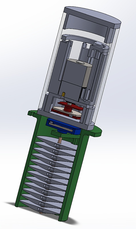
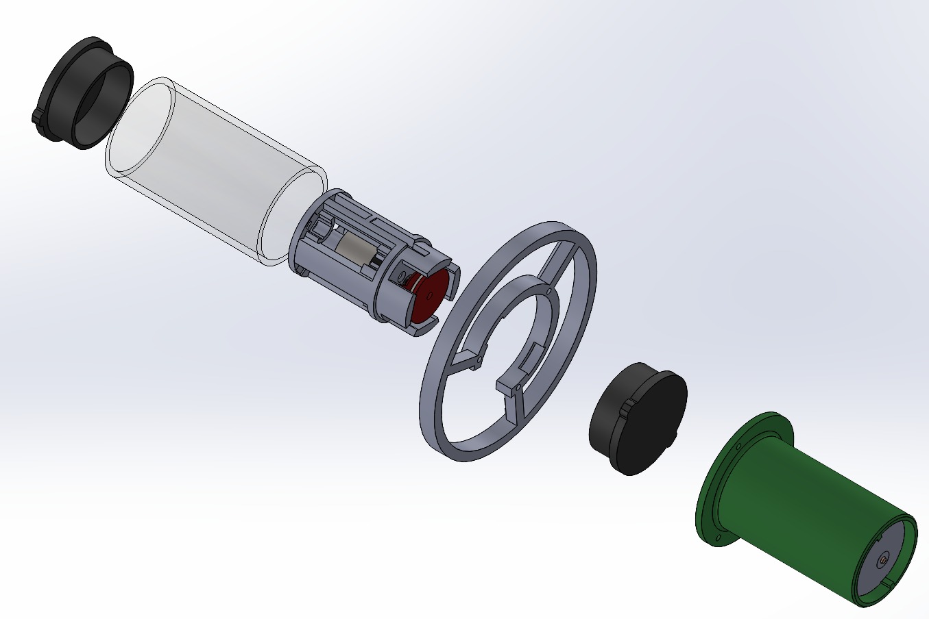
It can be divided in two sub-assembly:
- the outer part. It's a tube enclosing the discs. The threaded rod is connected to the outer magnetic coupler. It is held in place by a beam in the top part of the tube.
- the inner part. It's enclosed in a watertight PMMA tube. This tube has two aluminum end-caps.
Col
Inner part construction
Magnetic couplers
Here is the magnetic coupler assembly steps:
- Mark one pole of the magnets (the same for all magnets), so that you can put them in the right way.
- Place (press-fit) the magnet in this order, so that the perturbations are minimal:
Col

Col

Col

- Place the steel washer
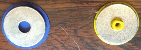
On this picture, we can see both part of the coupler. On the left, the external one (connected to the discs). On the right, the internal one, connected to the motor.
Sensor(s) assembly
In the first version, I used two optical sensors to detect the motor position.
They were glued on the bottom 3D-printed part:
Col

Col

Col

Wires are directly soldered on the sensor's pins.
Battery holder
The battery contacts are soldered on a single-core wire.
The left picture shows the positive contacts glued on the top 3D-printed part. The middle picture shows the negative contacts glued on the middle 3D-printed part. The third picture shows both 3d-printed parts glued together to create the battery holder:
Col

Col

Col

Internal assembly
- Screw the motor on the bottom part:

- Glue the bottom part to the battery holder (left picture)
Col

Col

Col

-
Press-fit the coding disc on the motor shaft (middle picture)
-
Press-fit the internal magnetic coupling disc on the motor shaft (right picture).
PCB
-
Solder the wires coming from the motor, the batteries and the sensors on the PCB
-
Glue the PCB on the top of the battery holder

Outer part assembly
Coupling disc assembly
- The magnets and washer assembly is identical as the inner coupling disc in the 3D-printed part on the right in the video
- The other part is attached to the threaded rod with two nuts. One is press-fit in the part and the other is covered with a third 3D-printed part. This part also acts as thrust bearing for the rod
- Both 3D-printed parts are sealed by casting silicone between them.
Discs assembly
- Place the threaded rod in the disc holder.
- place a mark on its top to help counting turns.
- Place a disc at the bottom of the rod. Turn the rod by hand, for 11 turns.
Indeed, a turn makes the discs move 0.5 mm up or down.
A disc is 5 mm thick. Hence, I chose a disc pitch of 11 turns (with 0.5 mm gap between discs)
- Repeat the operation for the remaining discs.
Electronics
Version 1
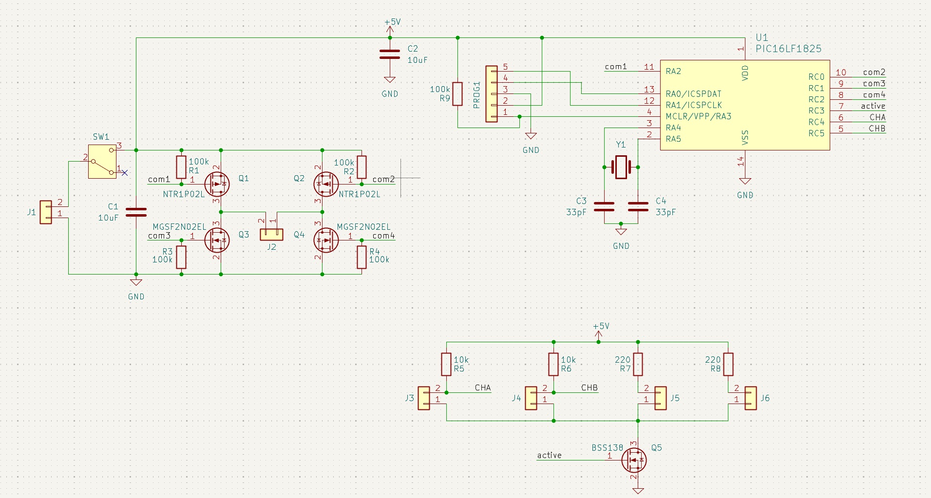
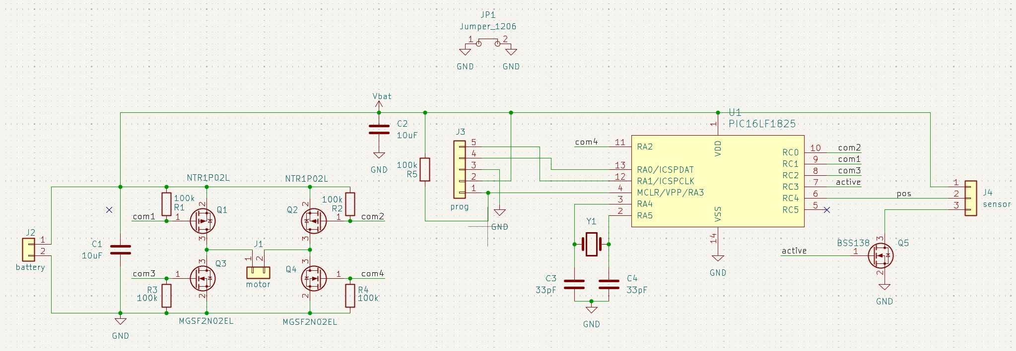
The electronics is built around a PIC16LF1825.
I chose it because I use PIC microcontrollers in my projects for 20 years.
This particular microcontroller is well suited for very low power systems, with an efficient sleep mode.
Its oscillator is driven by a 32.768 kHz crystal.
As the code is simple and has no challenging time constraint, this frequency is more than enough.
Running at low frequency reduces the power consumption.
The clock has to be accurate, as it's also used to count time. This is why I used a crystal instead of the internal oscillator.
The motor is driven by a H-bridge, made of 2 NMOS transistors (Q3 and Q4) and 2 PMOS transistors (Q1 and Q2).
It makes it easy to control directly by the microcontroller:
- to turn a NMOS on, set its control signal (COM3/COM4) to 1
- to turn a PMOS on, set its control signal (COM1/COM2) to 0
THe optical sensors are a phototransistor with a matching LED.
- J3 and J4 are connected to the phototransistors
- J5 and J6 are connected to the LEDs
Version 2
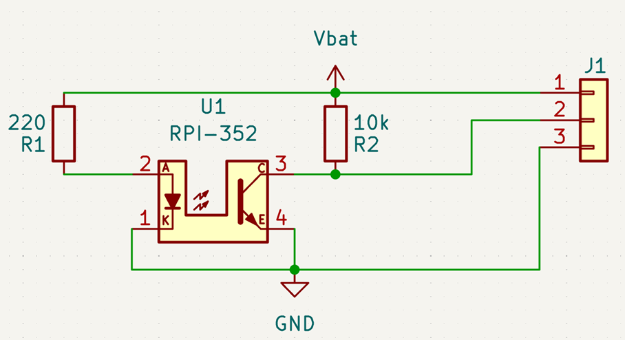
After assembling the first prototype, I made a second version of the version of the electronics, with the following improvements:
- I only used one sensor. I tested this solution on the first prototype; We don't need to measure the rotation direction, as we only make slow and unidirectional movements.
- I removed the power switch. It has little purpose and take space.
- I made a dedicated PCB for the sensor, to ease its mounting in the disc dispenser and make the assembly more robust.
- I moved the sensor's resistors on its PCB to gain space on the main PCB
Code
I like structured code. Hence, I divided it in several source file, based on functionalities.
dateTime.c
This file contains the functions to count time:
void dateTime_init(void)initializes the variables and configures TIMER1 to use the external crystal oscillator as inputvoid dateTime_update(void)has to be called each time TIMER1 overflows. Tjis is done in the corresponding ISR (in main.c). It updates the variable containing the current time.int8_t dateTime_isMidnight(void)checks if current time is midnight. It can be used to trigger a daily operation.int8_t dateTime_isNewMonth(void)checks if current day is the first of a new month (and if it's midnight). It can be used to trigger a monthly operation.dateTime_t dateTime_get(void)returns the current time.int8_t dateTime_compare(dateTime_t date1, dateTime_t date2)compares two time variables; It can be used to check an arbitrary deadline.
motor.c
void mot_init(void)initializes the position variables.void mot_stop(void)turns all transistors off.void mot_up(void)turns the Q1 and Q4 on to make the discs go up continuouslyvoid mot_down(void)turns the Q2 and Q3 on to make the discs go down continuouslyvoid mot_up_turn(uint8_t dist_mm)usesmot_up()to move the discs up a given distance. It uses the sensor to update the motor positiob variablevoid mot_down_turn(uint8_t dist_mm)usesmot_down()to move the discs up a given distance. It uses the sensor to update the motor positiob variable
pins.c
This file contains only one function, void pin_init(void) that initializes all pins of the microcontroller
main.c
Besides main(), this file contains 3 functions:
void __interrupt() isrHandler()that is the ISR for TIMER1 overflow. It callsdateTime_update()and is executed every 2 seconds.void cleaning(void)moves the discs up 3 mm, then it moves them back down 3 mm. This function is called bymain.conce a day. It's purpose is to prevent fouling from blocking mechanism.void dropDisk(void)moves the discs down 6 mm, releasing the bottom one. It then moves up 1 mm . The extra mm ensures that the disc is released.
main()
Its structure is fairly simple:
- First it initializes the motor and the time counter.
- Next, it defines the disc drop dates:
for (uint8_t i=0; i<DISK_NB; i++) {
    dropDates[i].months = (INITIAL_DELAY + i*DROP_DELAY) / 30;
    dropDates[i].days = (INITIAL_DELAY + i*DROP_DELAY) % 30;
    dropDates[i].hours = 0;
    dropDates[i].minutes = 0;
    dropDates[i].seconds = 0;
}
INITIAL_DELAY and DROP_DELAY are defined at the top of the file to ease the parametrization of the code.
- It also defines the cleaning period as 2 days.
- Booting sequence ends with a first cleaning operation. It allows the operator to see that the system is working after inserting the batteries.
- The main loop starts by going to sleep
- it's awaken by TIMER1 overflow
- the code first checks if it's time to drop a disc
- If so, it started a drop operation
- If not, it checks if it's time for a cleaning operation
- If so, it started it
Tests
First test: cleaning sequence, motor only
I first tested the motor position sensing on the inner part of the disc dispenser. As the code started with a cleaning operation, one can immediately see if the motor and sensors are working.
I had some malfunction at first: motor rotation was shaky. After some investigation, I found out it was one of the motor's wire that has to be re-soldered.
Afterwards, the cleaning sequence works fine:
Further tests
Next, I assembled the disc dispenser and made the same test with only one disc on threaded rod, to see if the magnetic coupling is able to move the external part.
This test was successful.
Finally, I mounted all discs and tested the drop operation. For that purpose, I change the code to drop a disc every 20 seconds:
Power measurement
I checked the motor power with a power source and a multimeter: I measured 60 mA which is under the 100 mA I used in my energy budget.
Version 2
This pictures shows the sensor PCB I made for the second version:
Col

Col
