✦ How It Started?
For many children, nighttime can feel unfamiliar, vulnerable and sometimes even frightening. When the lights go out, ordinary objects can seem different, shadows become larger and the comfort of daytime disappears. This idea emerged from a personal experience with my younger sister, who often felt uneasy when the lights were turned off.
Watching those moments made me wonder whether a lamp could become more than a source of illumination. Could it create a sense of presence? Could light itself become a companion during those quiet moments before sleep?
✦ Project Proposal
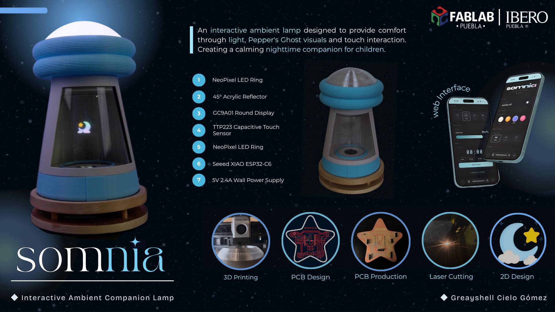
Somnia is an interactive ambient lamp designed to provide companionship during nighttime moments through light, holographic visualization and intuitive interaction. By combining digital fabrication, embedded electronics and programming, the project creates a calming environment where light becomes both functional and experiential.
✦ Inspiration & References
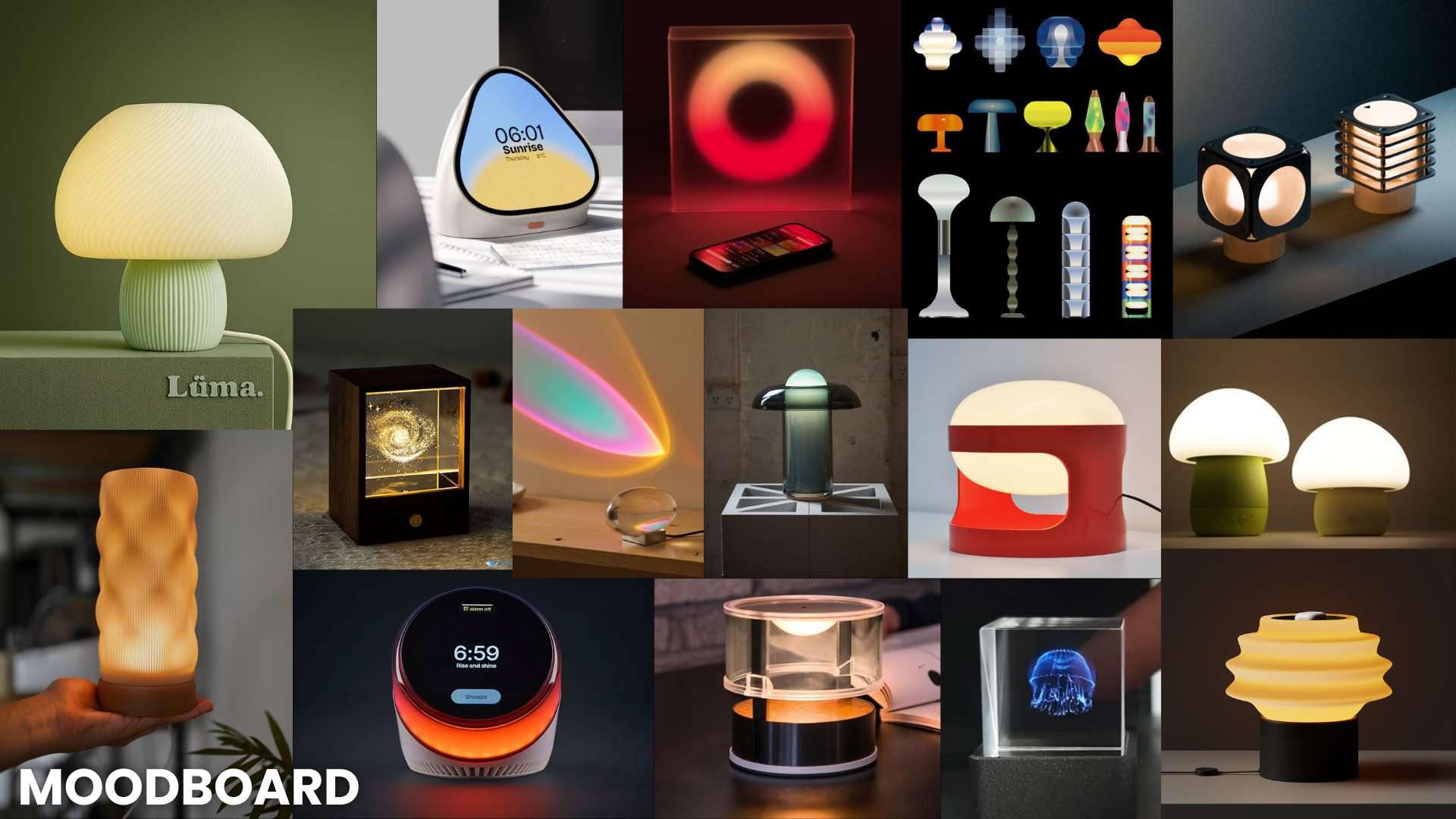
The project was inspired by kinetic product design, atmospheric lighting installations, calm technology concepts and Pepper's Ghost holographic systems. Existing references often separate movement from emotional interaction, so this project aims to integrate both into a single cohesive object.
✦ Initial Sketches & Form Development
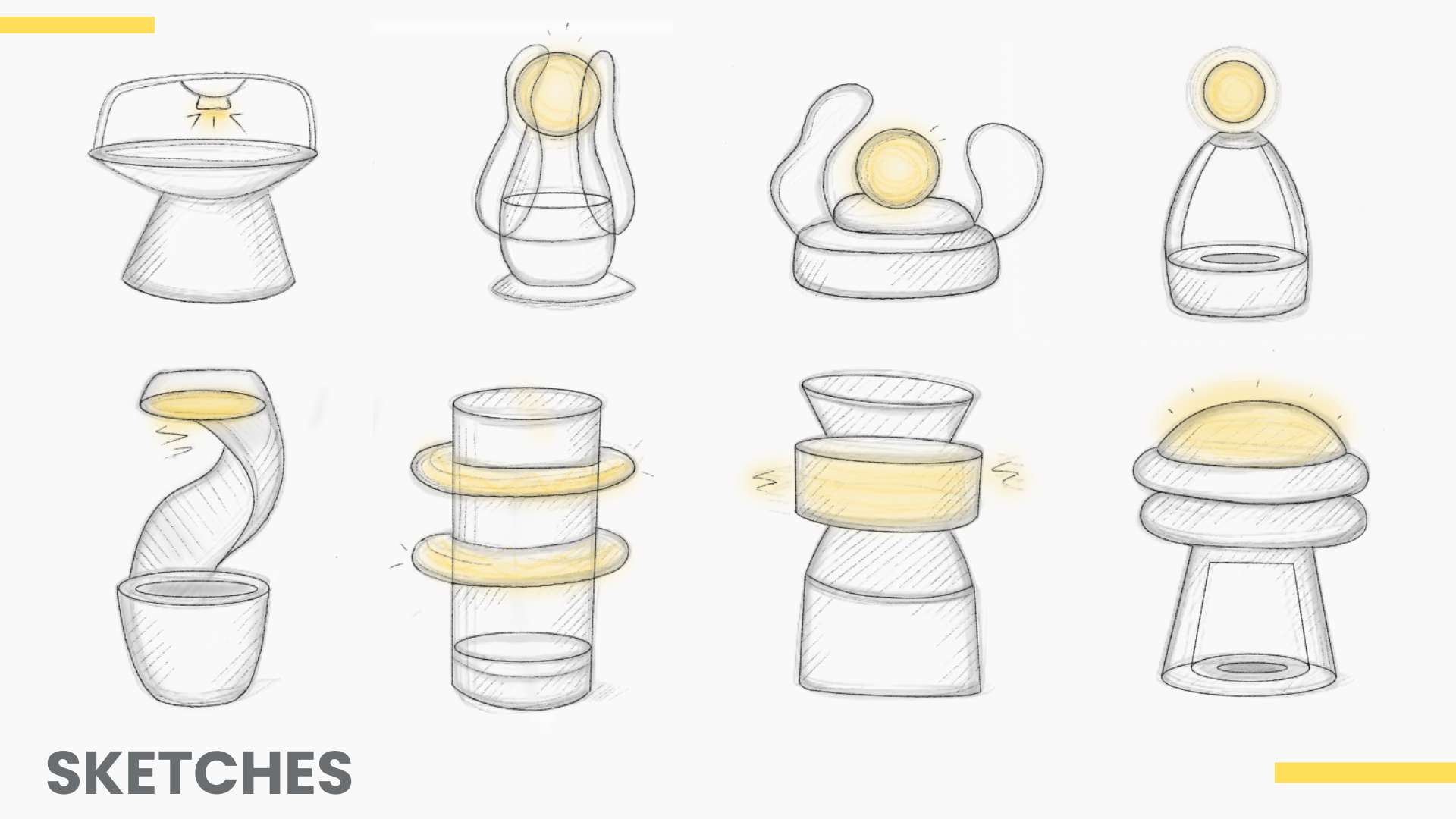
Multiple sketches and iterations were developed to explore the relationship between the holographic system and the overall emotional language of the lamp. The final direction evolved toward a soft mushroom-like silhouette with illuminated floating rings and a holographic central structure.
✦ What will you design?
All physical and electronic components are designed from scratch. The following elements were developed during the project:
Enclosure
- Lamp outer structure
- Mushroom-inspired form
- 3D printed parts
Holographic Chamber
- Acrylic reflector 45°
- Display housing
- Laser cut base
Electronics
- Custom PCB
- Touch interface
- WiFi web interface
Lighting
- NeoPixel system
- Color modes
- Diffuser dome
✦ Interaction Logic
The interaction system was designed to provide a simple and intuitive experience. Through touch and WiFi connectivity, users can control the lamp's lighting and holographic effects, allowing the different visual subsystems to work together as a unified ambient experience.
Interaction Logic
The lamp operates through two states: OFF and ON. A touch on the TTP223 sensor activates the NeoPixel lighting and holographic display. Additional touches cycle through three lighting modes, while the GC9A01 display generates static images for the Pepper's Ghost holographic effect through the web interface.
✦ What materials and components will be used?
✦ Estimated Components Cost
✦ Modeling the Enclosure
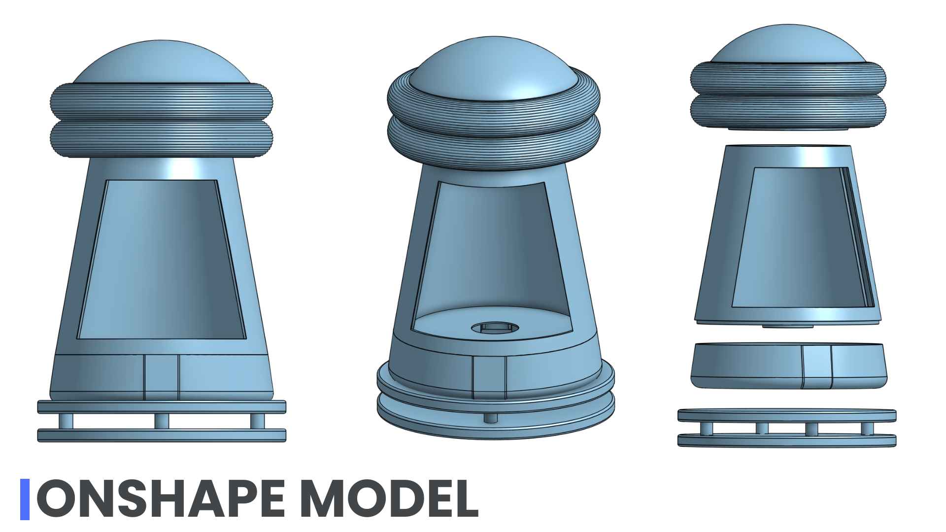
The enclosure was designed in OnShape. The mushroom-inspired form references soft organic shapes while maintaining structural rigidity. The lamp is composed of three stacked sections: the upper translucent dome (diffuser), the central holographic chamber, and the lower base (electronics compartment). For additional Onshape details go to my Week 2 .
01. Final Lamp Assembly
This is de final assembly of the lamp after designing and integrating all the components.
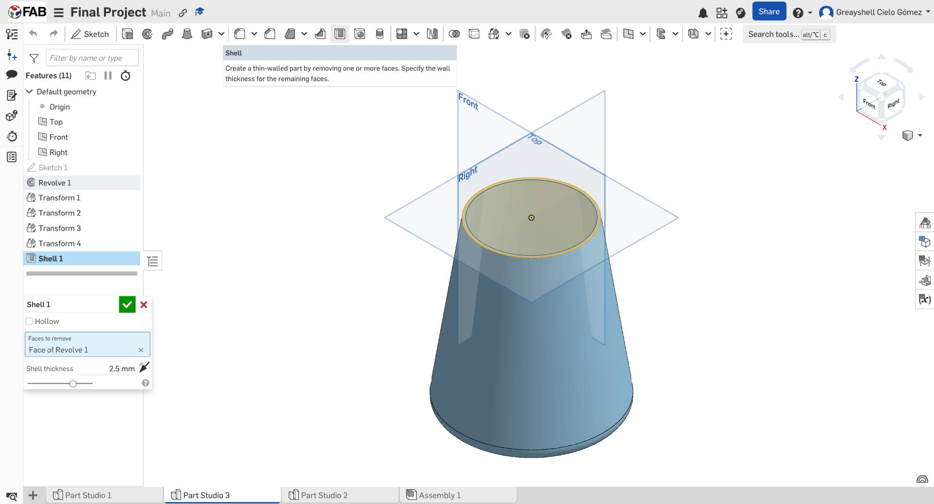
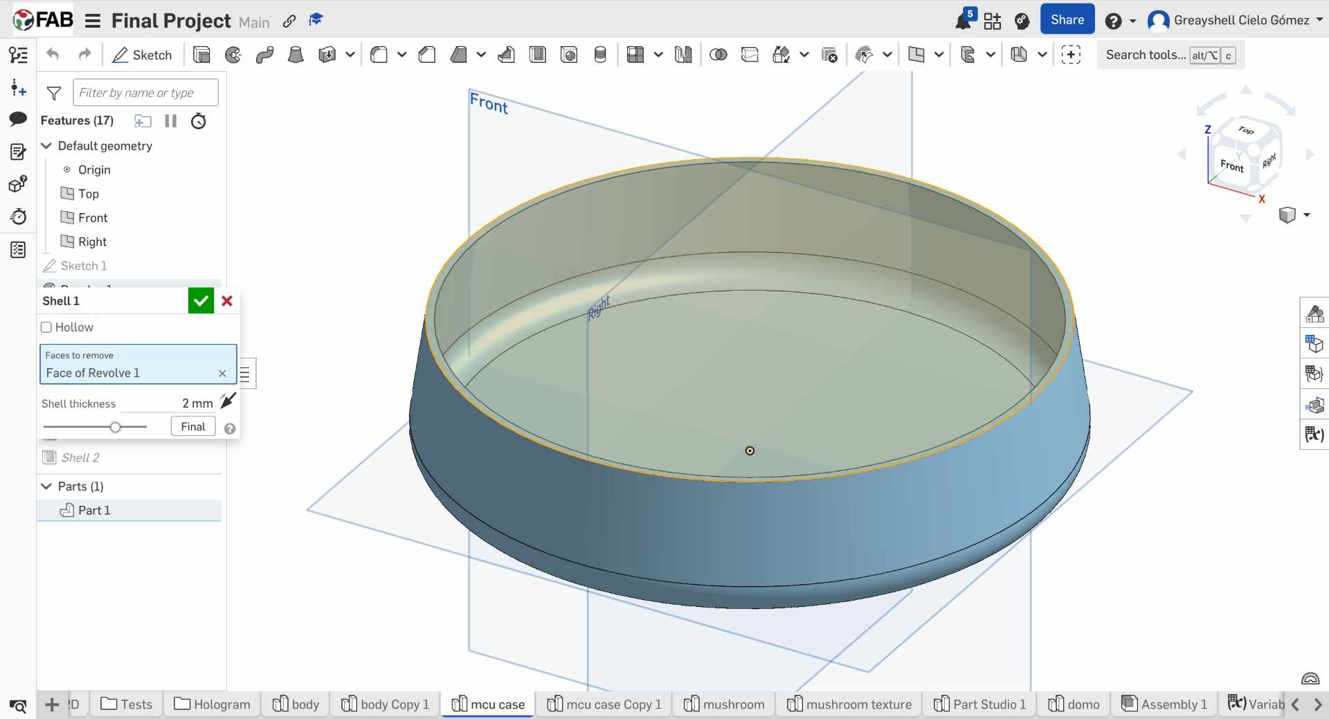
02. Creating the Main Enclosure
I started by creating the main body of the lamp using a revolved profile. To reduce material usage and create internal space for the electronics, I applied a 2 mm shell operation to hollow the part.
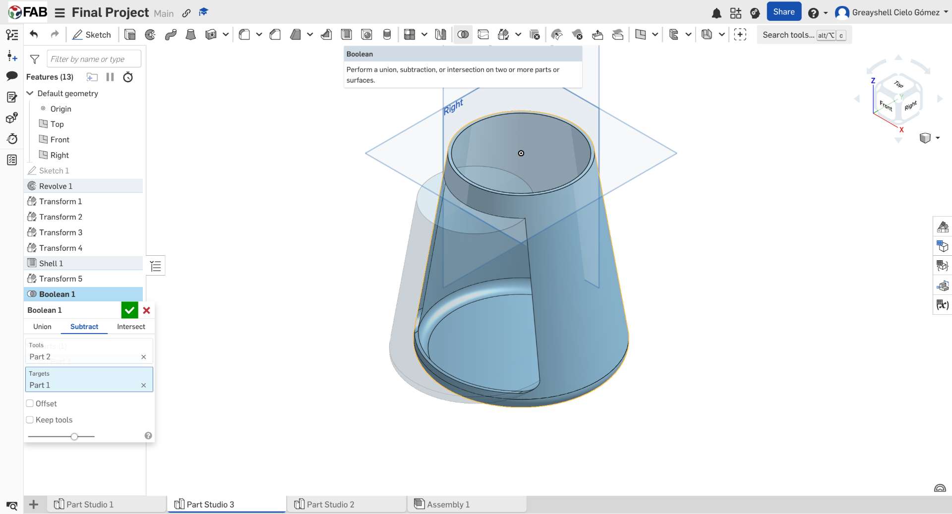
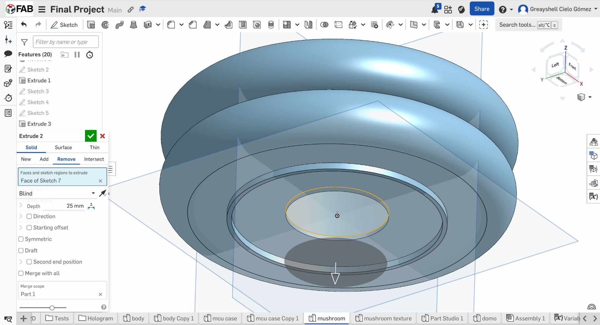
03. Boolean Subtraction for Internal Space
To create the interior volume, I duplicated and scaled the body, then used a Boolean subtraction operation. This generated the internal cavity required to house the holographic system and electronic components.
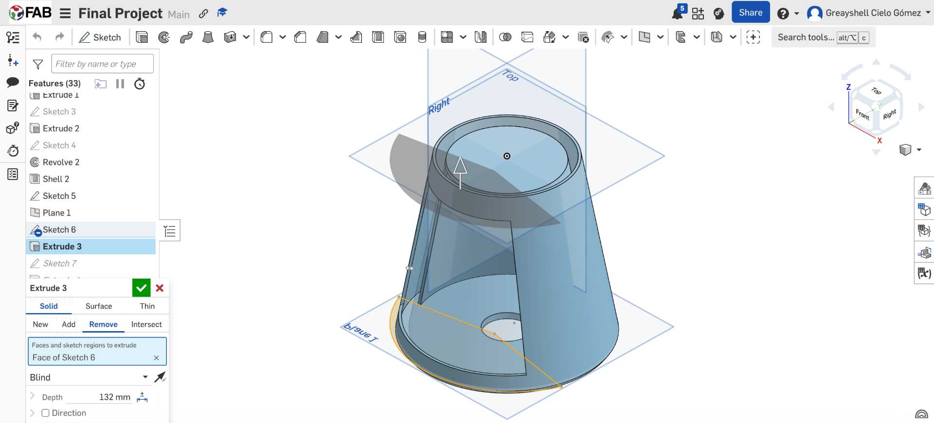
04. Exposing the Holographic Chamber
A fan-shaped sketch was created and extruded through the body to expose the interior of the lamp. This opening allows the holographic projection to be visible while maintaining the structural integrity of the enclosure.
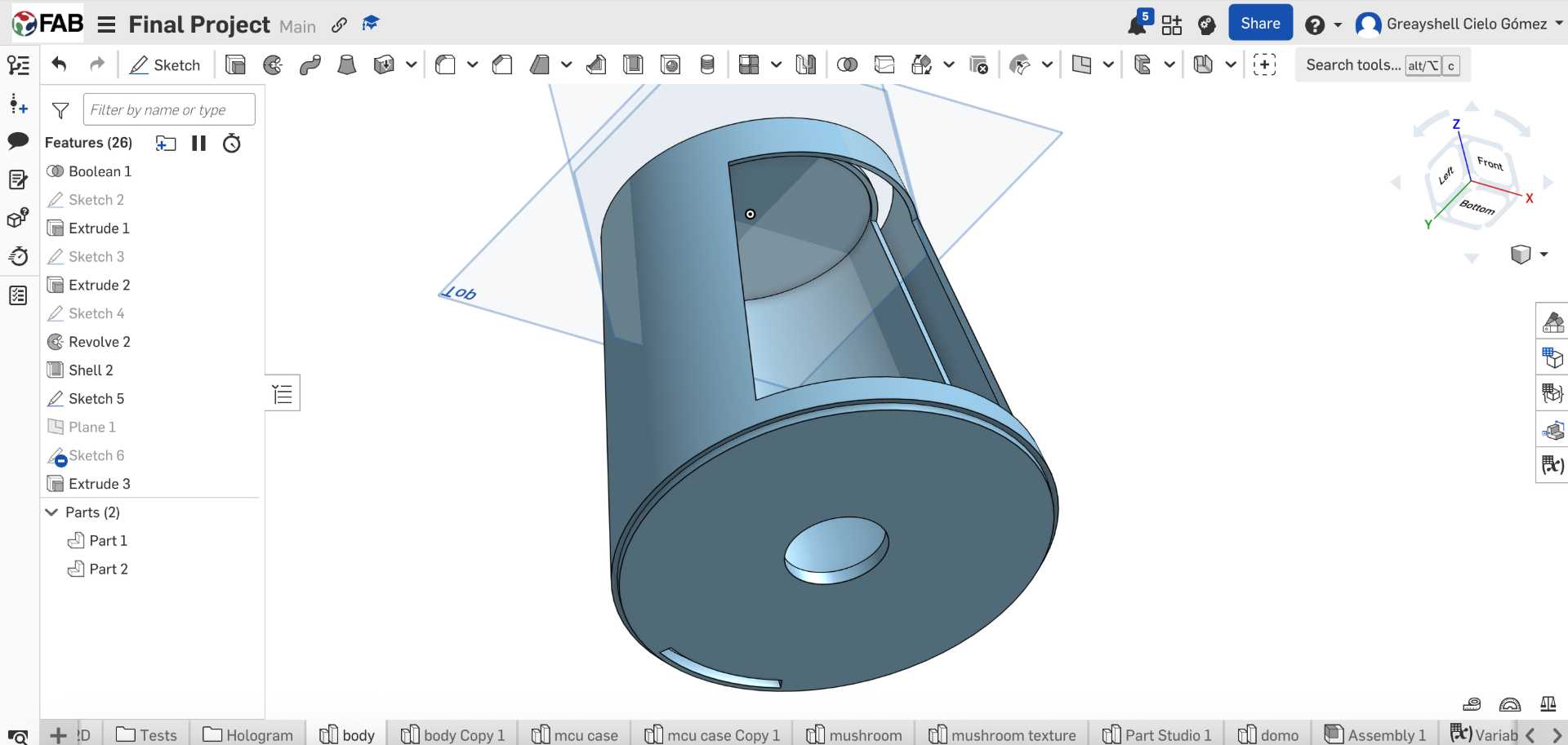
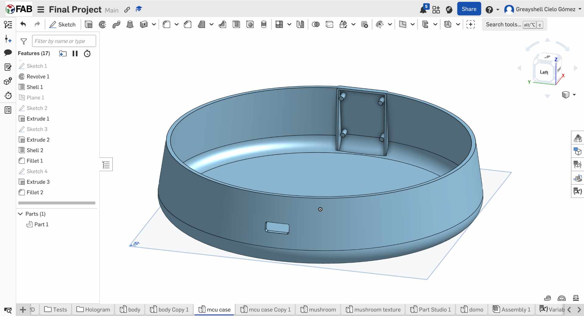
05. Internal Supports and Cable Routing
Inside the enclosure, I designed a dedicated compartment for the circular display and added a rear wall to route cables through a separate opening. A press-fit feature was also incorporated to connect the body with the base.
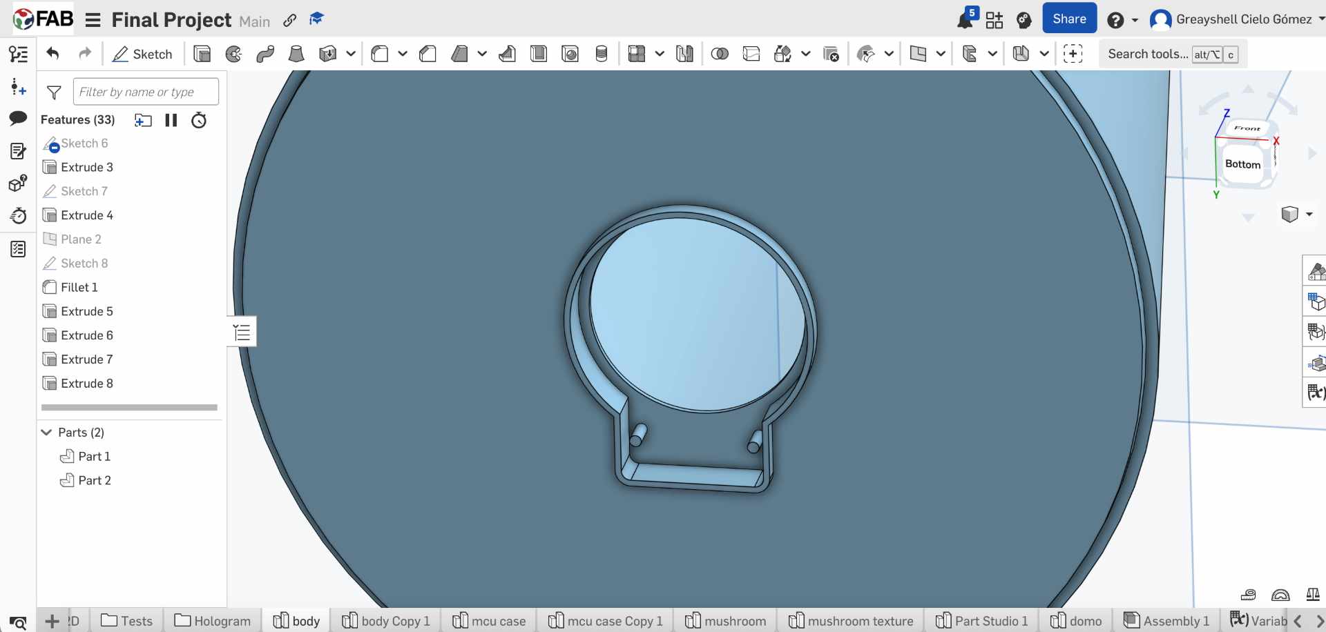
06. Press-Fit Display Mount
To secure the round GC9A01 display, I traced its geometry and designed a custom compartment. Small retention pins were added to create a press-fit connection, allowing the display to snap into place without additional fasteners.
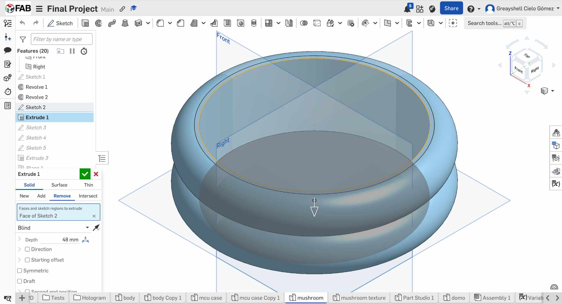
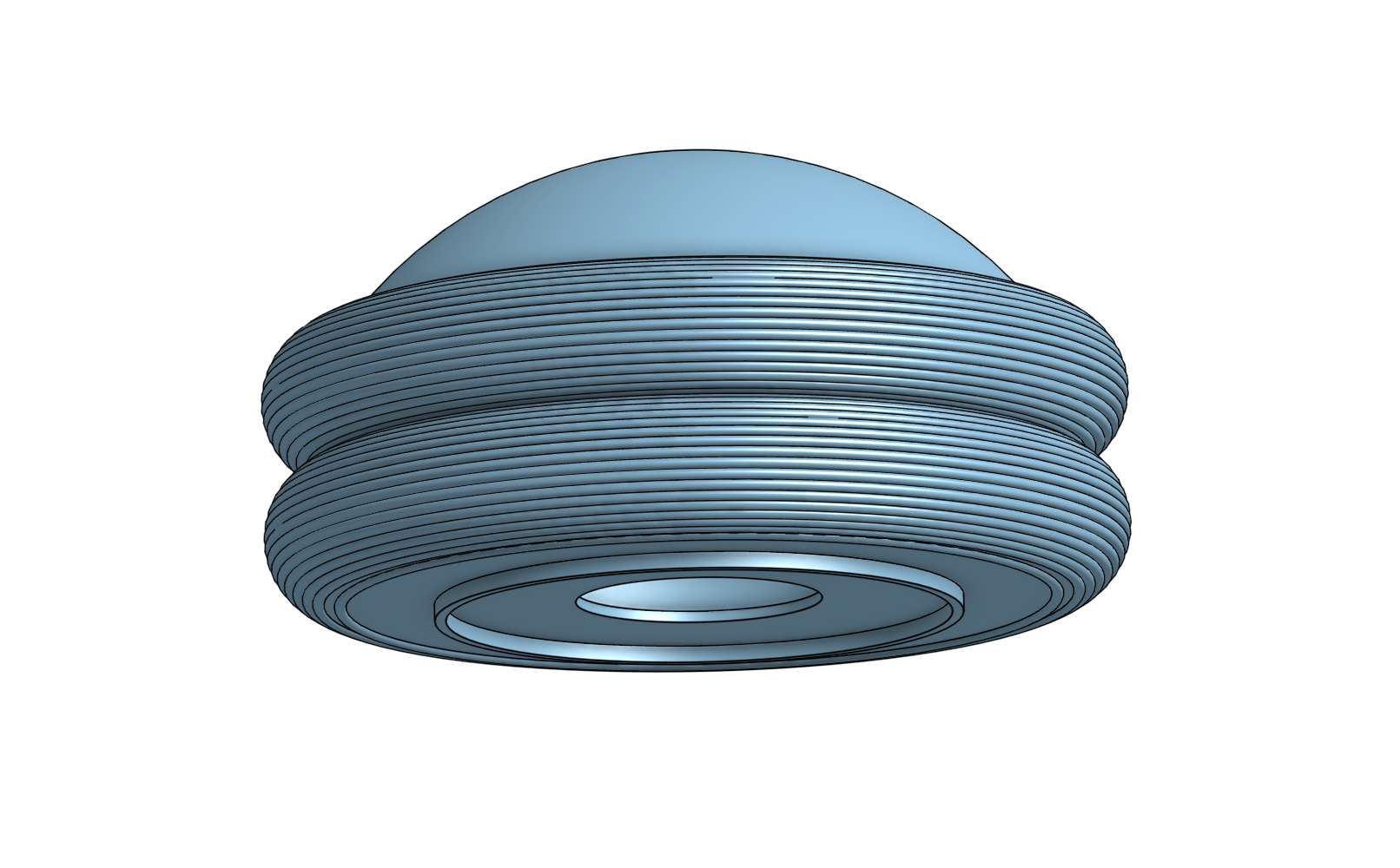
07. Designing the Upper Dome
The upper section of the lamp was created by revolving two overlapping semicircles and applying a shell operation. This geometry forms the housing that contains the NeoPixel ring and diffuses the emitted light.
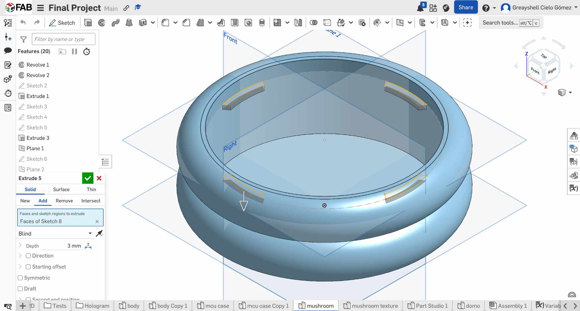
08. Adding Structural Tabs
Three internal tabs were added to support a circular plate inside the dome. This plate serves as the mounting surface for the NeoPixel ring and helps align the lighting system.
09. NeoPixel Ring Integration
A central opening was added to the internal plate to precisely position the NeoPixel ring. An additional press-fit feature was designed to securely connect the dome to the lamp body.
10. NeoPixel Plate
A plate was designed to insert the neopixel directly and fit inside the structure of the rings.
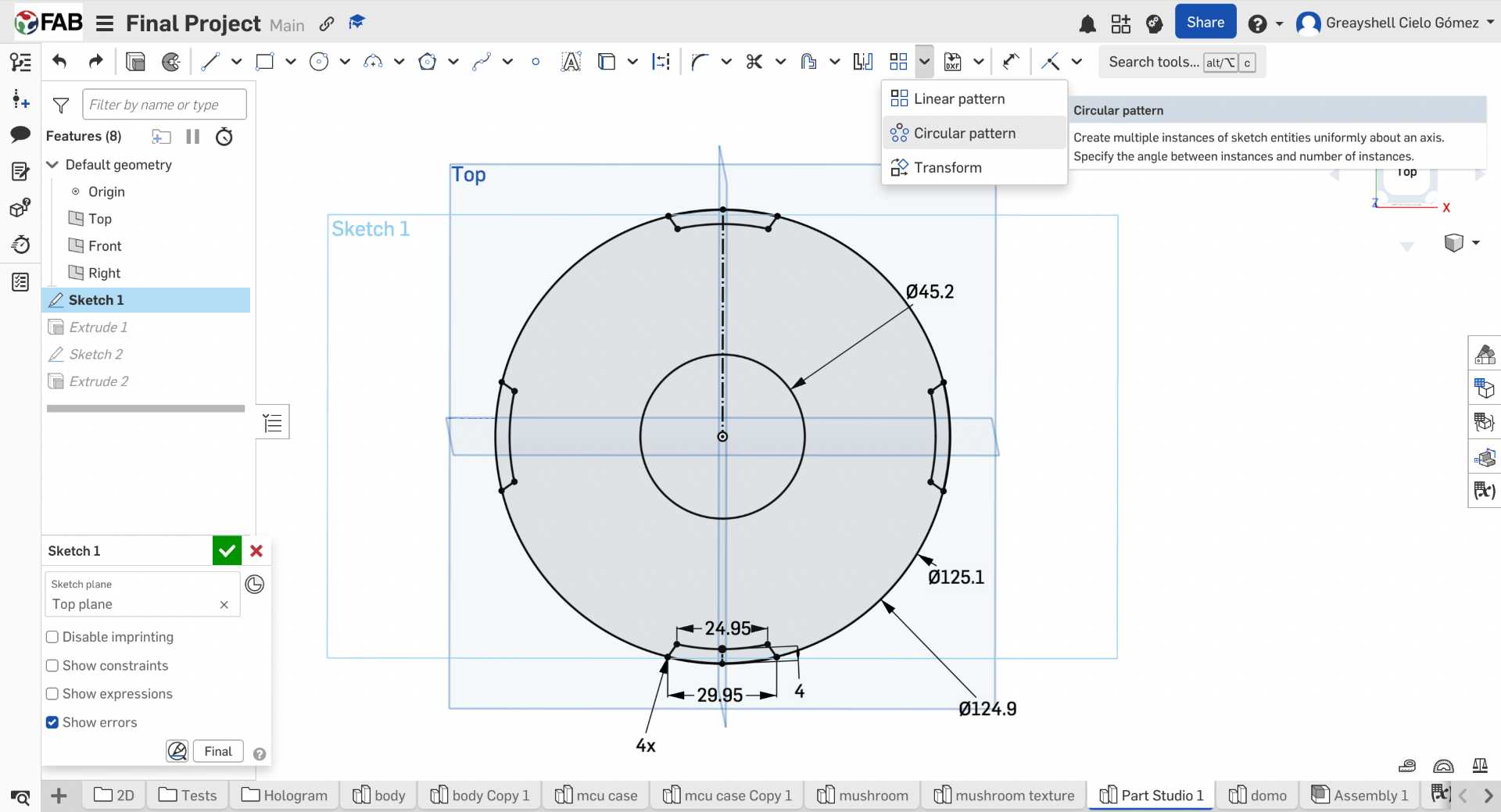
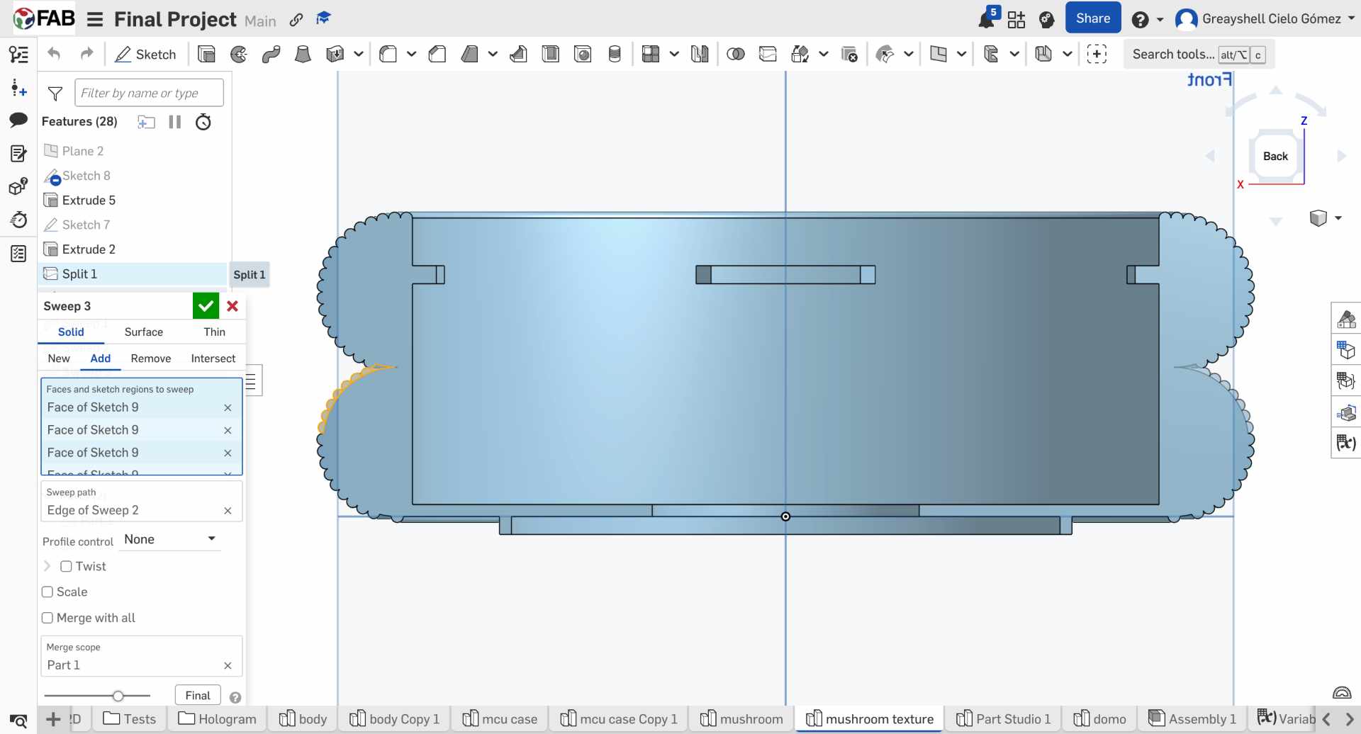
11. Creating the Layered Texture
To reinforce the visual identity of the project, I split the dome geometry and created circular profiles around its perimeter. Then I applied a sweep operation around the dome to create a continuous ring pattern.
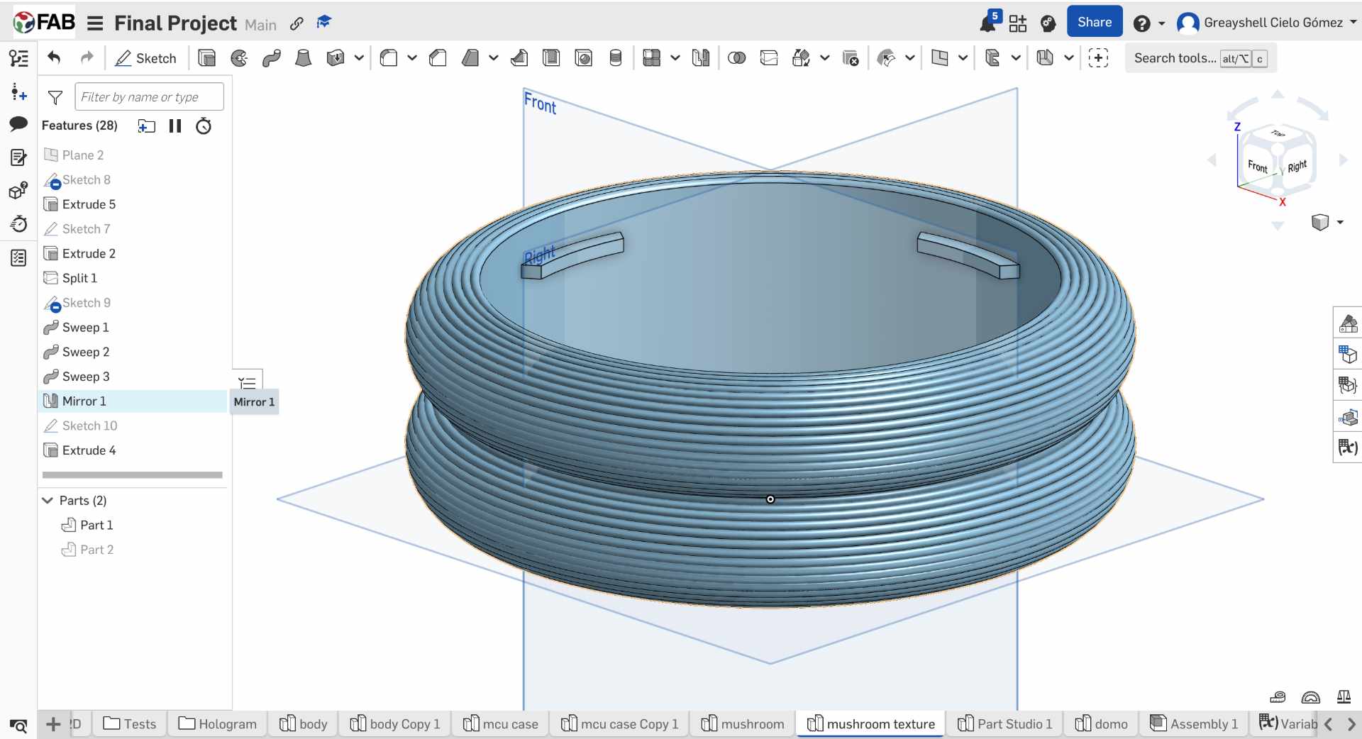
12. Completing the Rings Structure
After creating the textured section, I mirrored the geometry to generate the complete dome. This ensured symmetry while reducing modeling time.
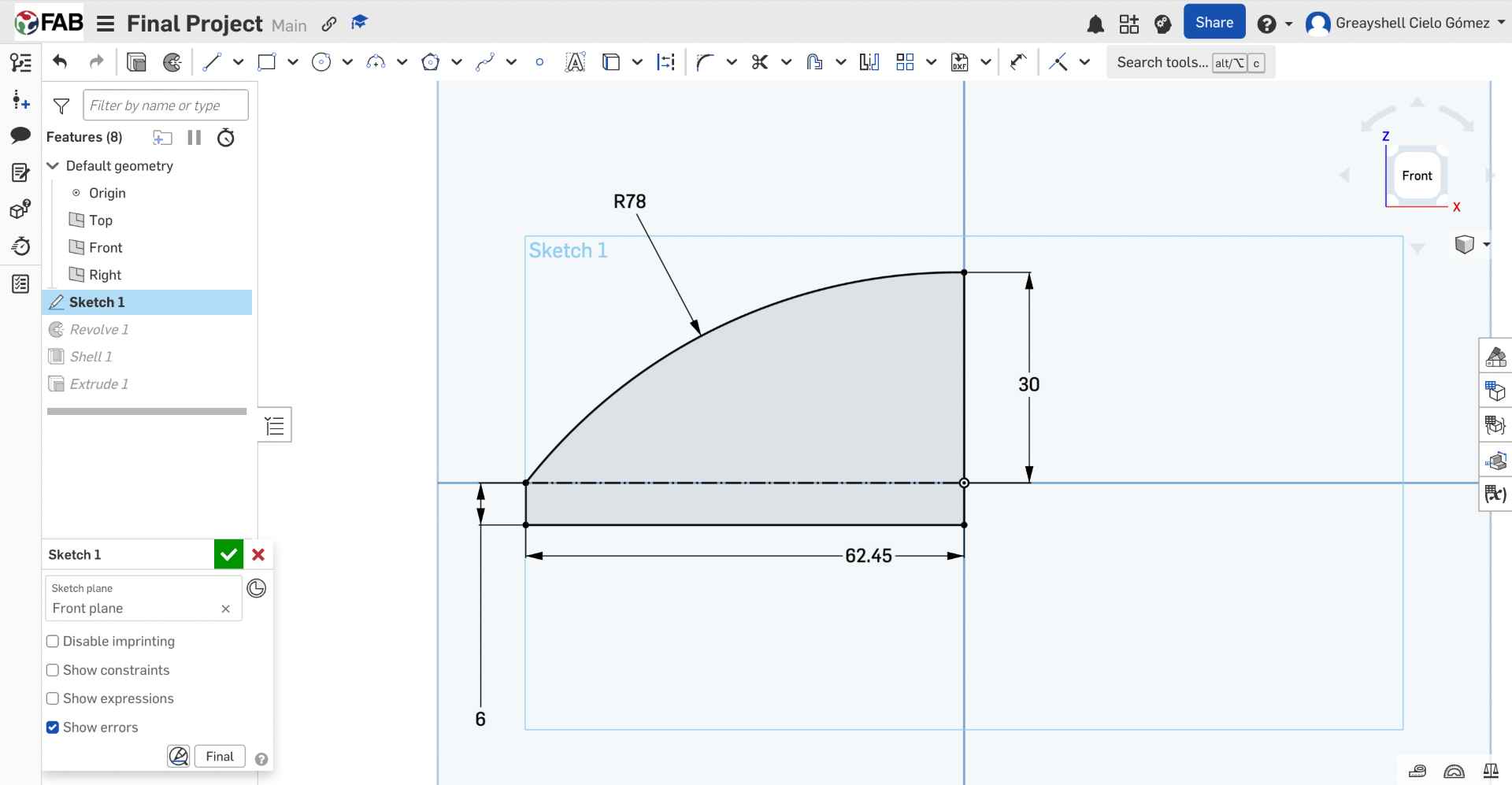
13. Dome Profile Sketch
The dome was designed from a simple curved profile sketched. The arc has a height of 30 mm and a radius of 78 mm. I also added a 6mm tab that will fit into the structure of the rings.
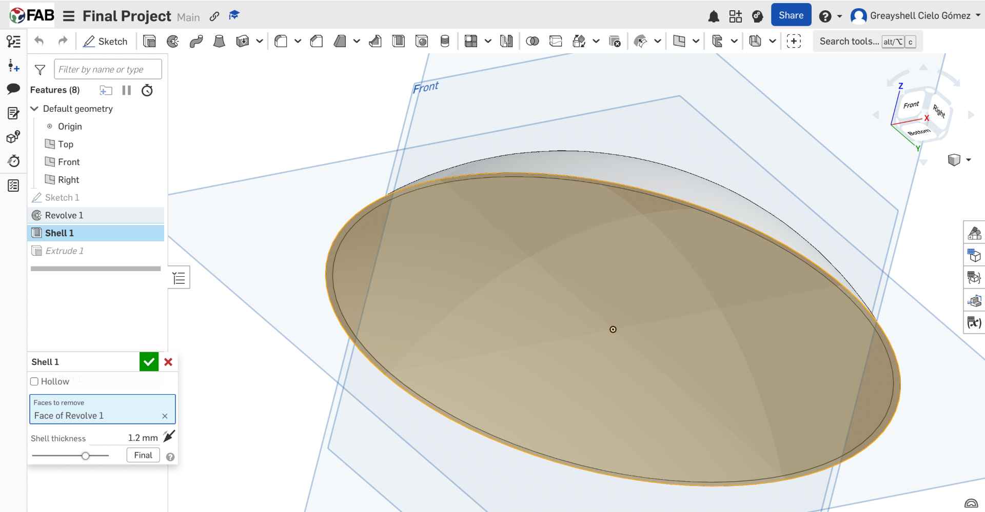
14. Shell Feature
After creating the dome shape, I Revolved de sketch and used the Shell feature to hollow the model and leave a wall thickness of 1.2 mm. This helped reduce material usage while keeping the dome lightweight.
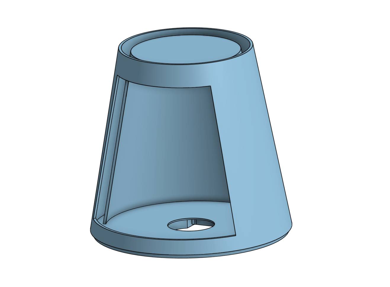
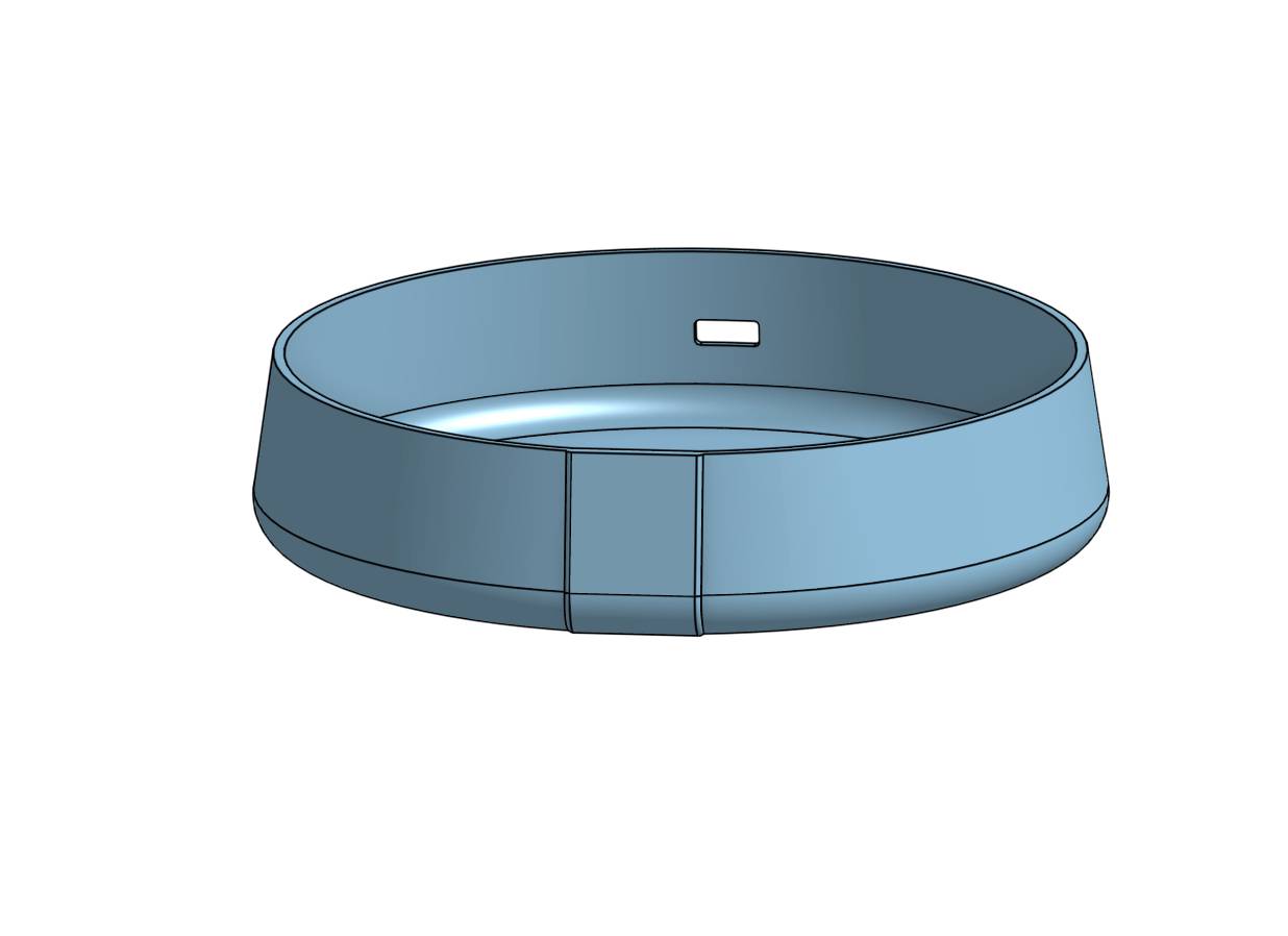
15. Base Construction
The base was modeled following the same design language developed during Week 2. A 2 mm shell operation was applied to create space for the electronics and wiring.
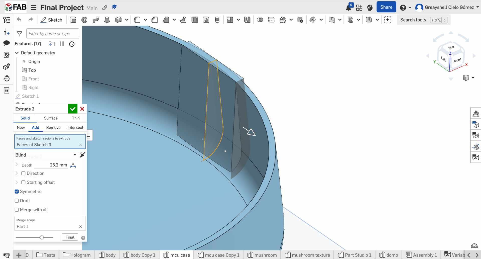
16. Touch Sensor Compartment
To integrate the TTP223 touch sensor, I created a centered sketch and performed a symmetric extrusion. The geometry was adjusted to match the sensor dimensions and allow proper positioning within the enclosure.
17. Support Pins
Then I made a Shell to create a 1 mm wall and extruded 3 mm the support pins so the component could be securely press-fitted.
Translucent Dome
Printed with PETG filament and 1 mm thickness for optimal light diffusion.
Holographic Chamber
Cylindrical cavity to eliminate the entry of light. The GC9A01 is at the compartment of the base.
Electronics Base
Base for mounting the PCB and the orderly installation of components.
✦ 3D Print Settings
Printer: Bambu Lab P1S — PLA / PETG filament
Layer height: 0.2mm standard · 0.12mm detail (dome)
Infill: Gyroid & Grid
Supports: Yes
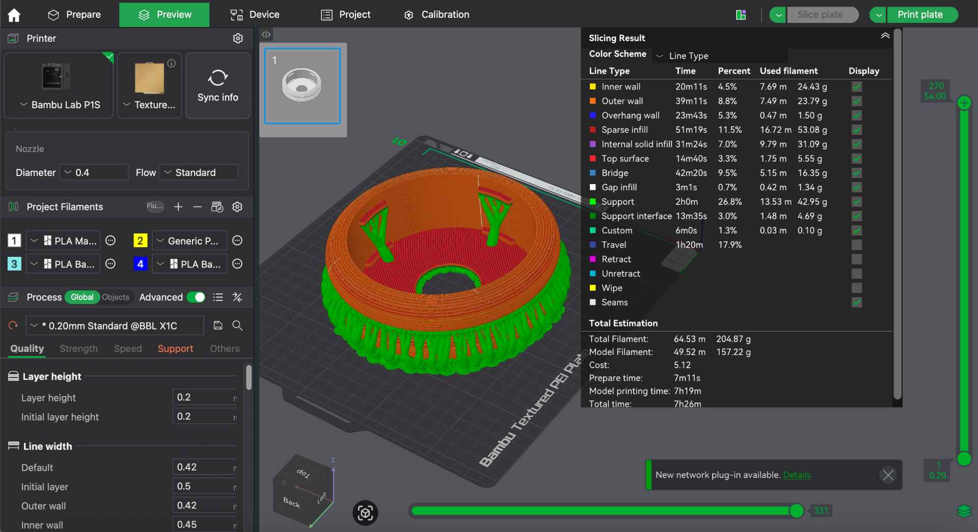
✦ Design Reflection
The first dome print came out opaque since it was too thick. Also, it was sent to print without supports and this resulted in a poor finish. That's why I changed from 2mm to 1mm wall thickness, and that gave the right diffusion without losing structural integrity. Also, to easily remove the supports, I set Top Z distance to 0.3 and Top interface layer to 3. For detailed 3D printing parameters, see my Week 5.
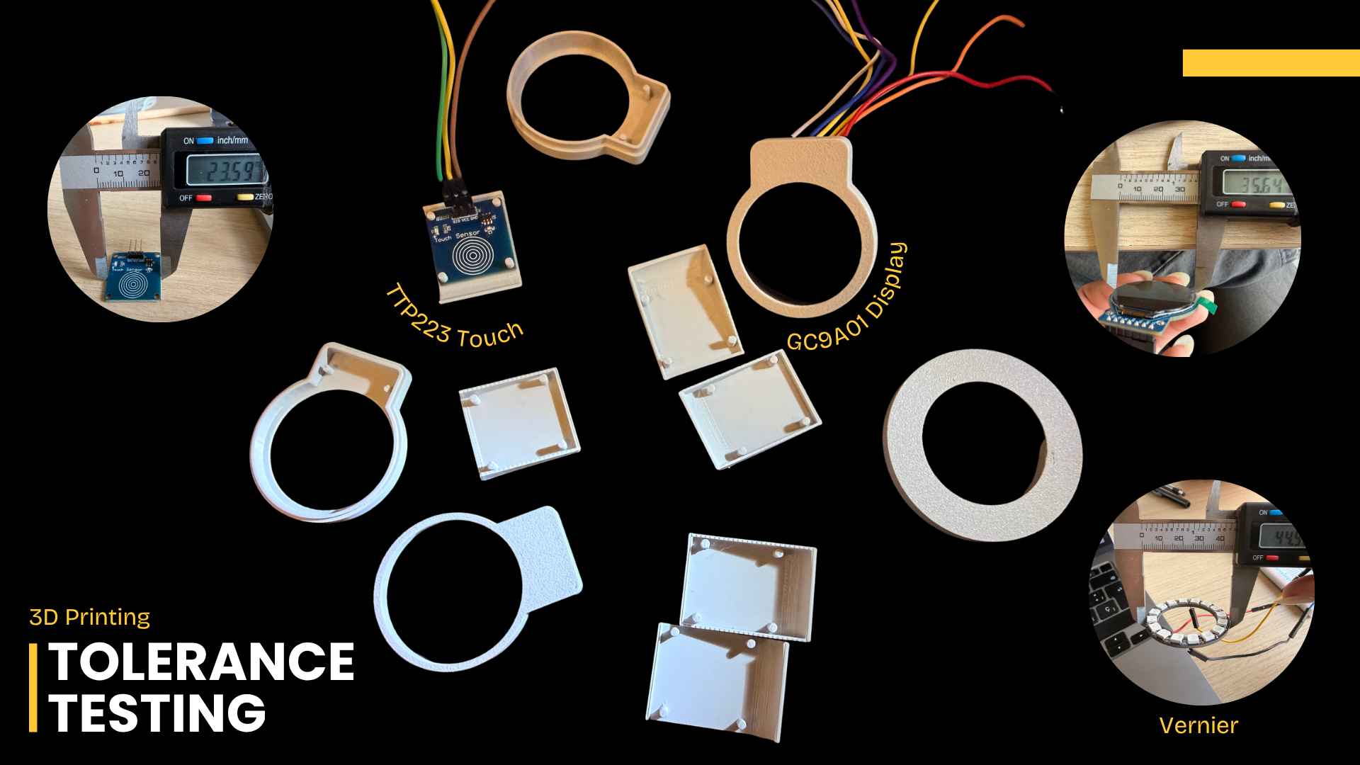
✦ Iterative Design Process
Throughout the design process, several prototypes were produced to test different tolerances for the round display and touch sensor. These iterations helped me to optimize the internal layout and ensure reliable integration of all components within the enclosure.
✦ Cutting the Reflector & Base
Two components were produced on the laser cutter: the acrylic 45° reflector that creates the Pepper's Ghost effect and the MDF structural base ring. Both were designed in Onshape and exported as DXF. For detailed laser cutting documentation, go to my Week 3.
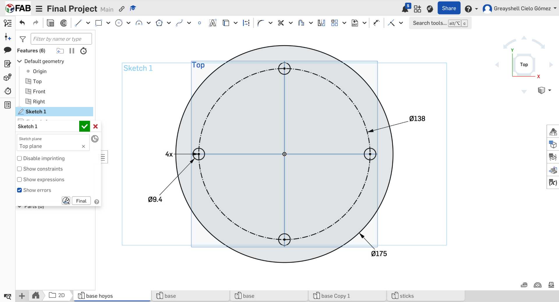
01. Base Design
I started by designing the base in Onshape. I created a circular piece with four 9.4 mm holes where the wooden sticks would later be inserted to connect the upper and lower parts of the structure. I also created two complete circles to serve as lids for these.
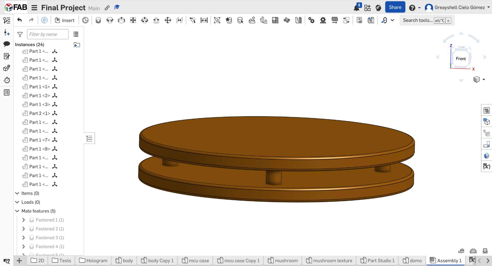
02. Base Assembly
After designing the individual pieces, I assembled them in Onshape to check that the discs and wooden sticks aligned correctly before moving on to fabrication.
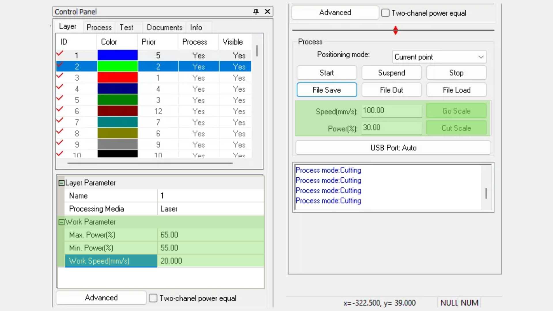
03. Laser Cutting Setup
Once the design was finished, I exported the files and arranged all the circular pieces in SmartCarve to make better use of the MDF sheet and prepare them for laser cutting.
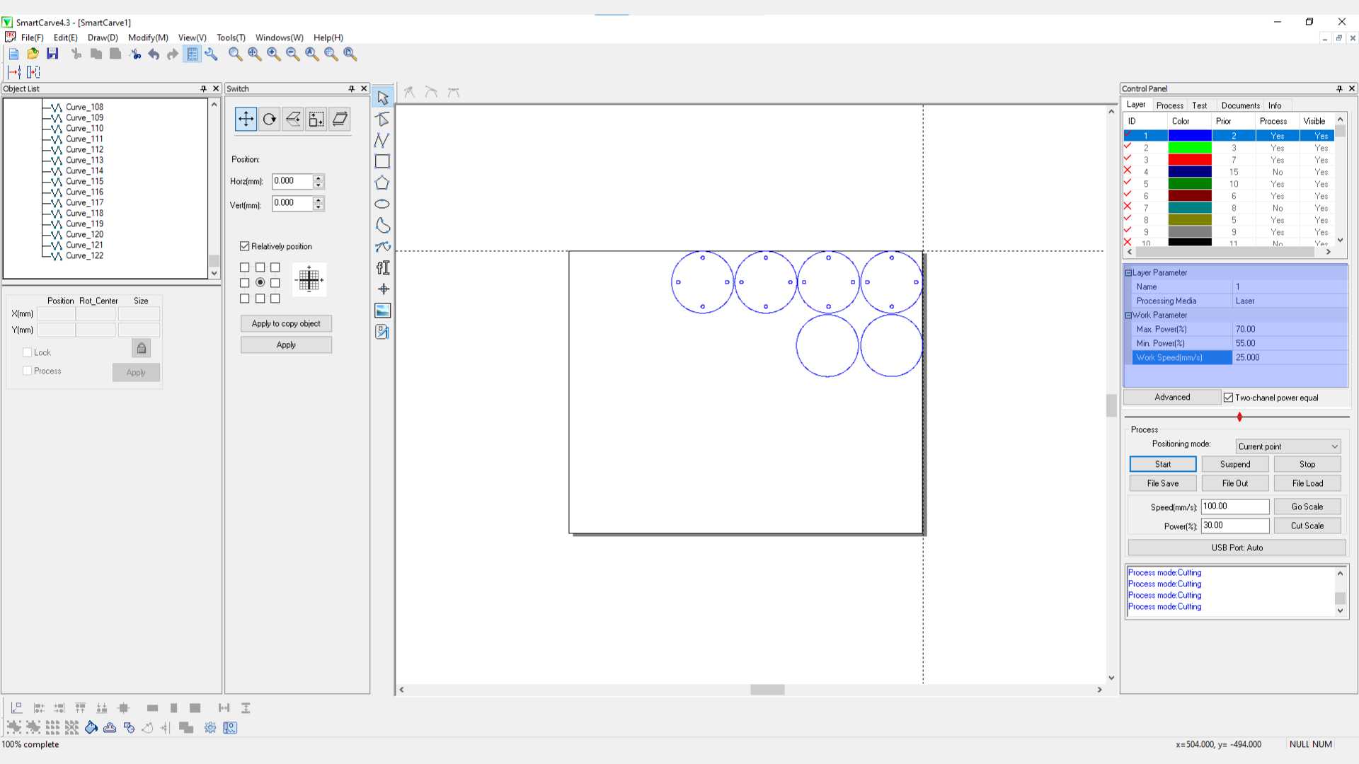
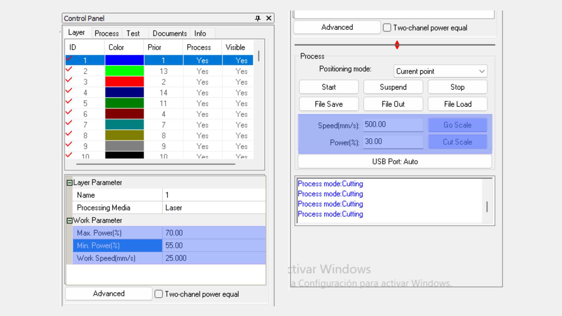
04. MDF Laser Parameters
Before cutting, I adjusted the laser settings in SmartCarve. I used these parameters because they provided clean cuts in the 3 mm MDF.
05. Pepper's Ghost Support Design
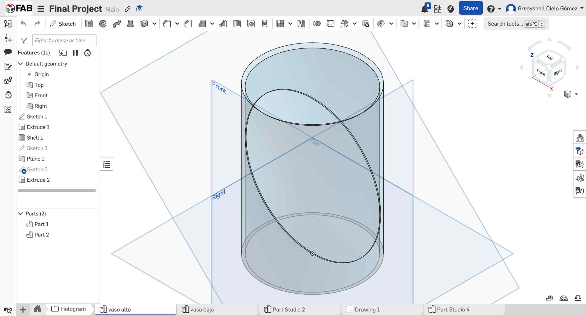
To create the Pepper's Ghost support, I first modeled the glass vase I had purchased. Then, I created a 45° plane inside the model, which would define the position of the acrylic reflector.
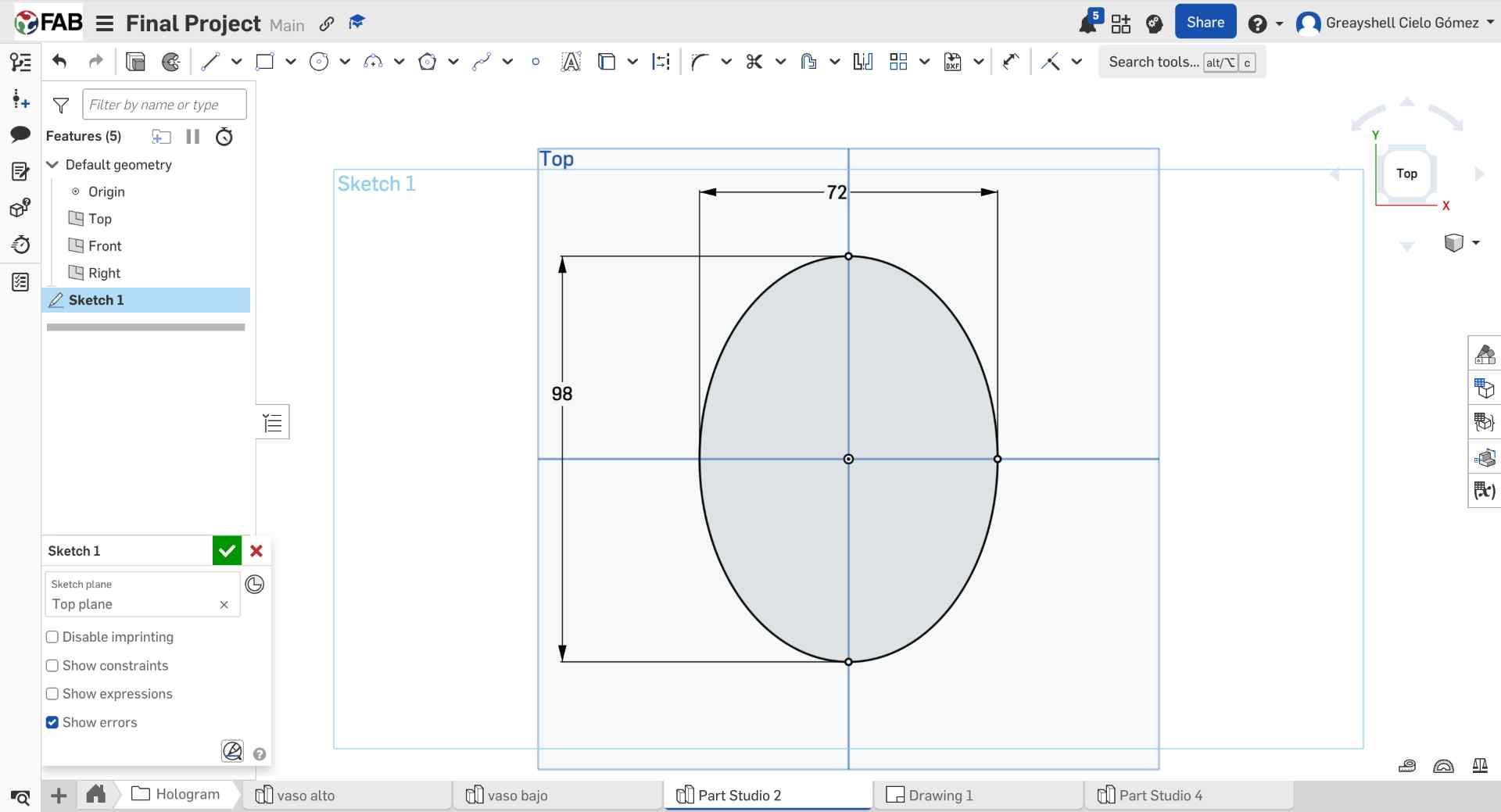
06. Acrylic Testing & Final Dimensions
Several oval versions with small dimensional variations were cut to test which one fit best inside the vase. This iterative process helped identify the most stable and accurate size for the hologram support.
07. Acrylic Cutting Setup
Since I was not sure which size would fit best, I prepared several oval variations in SmartCarve with small dimensional changes. This allowed me to compare them physically after cutting.
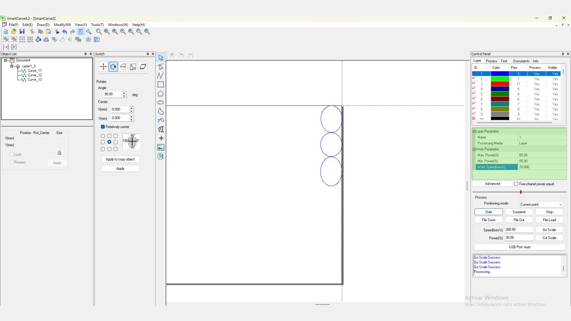
08. Acrylic Laser Parameters
Finally, I configured the laser parameters for the 2 mm acrylic and cut the different test pieces. After testing them inside the vase, I selected the oval that provided the best fit and positioning for the system.
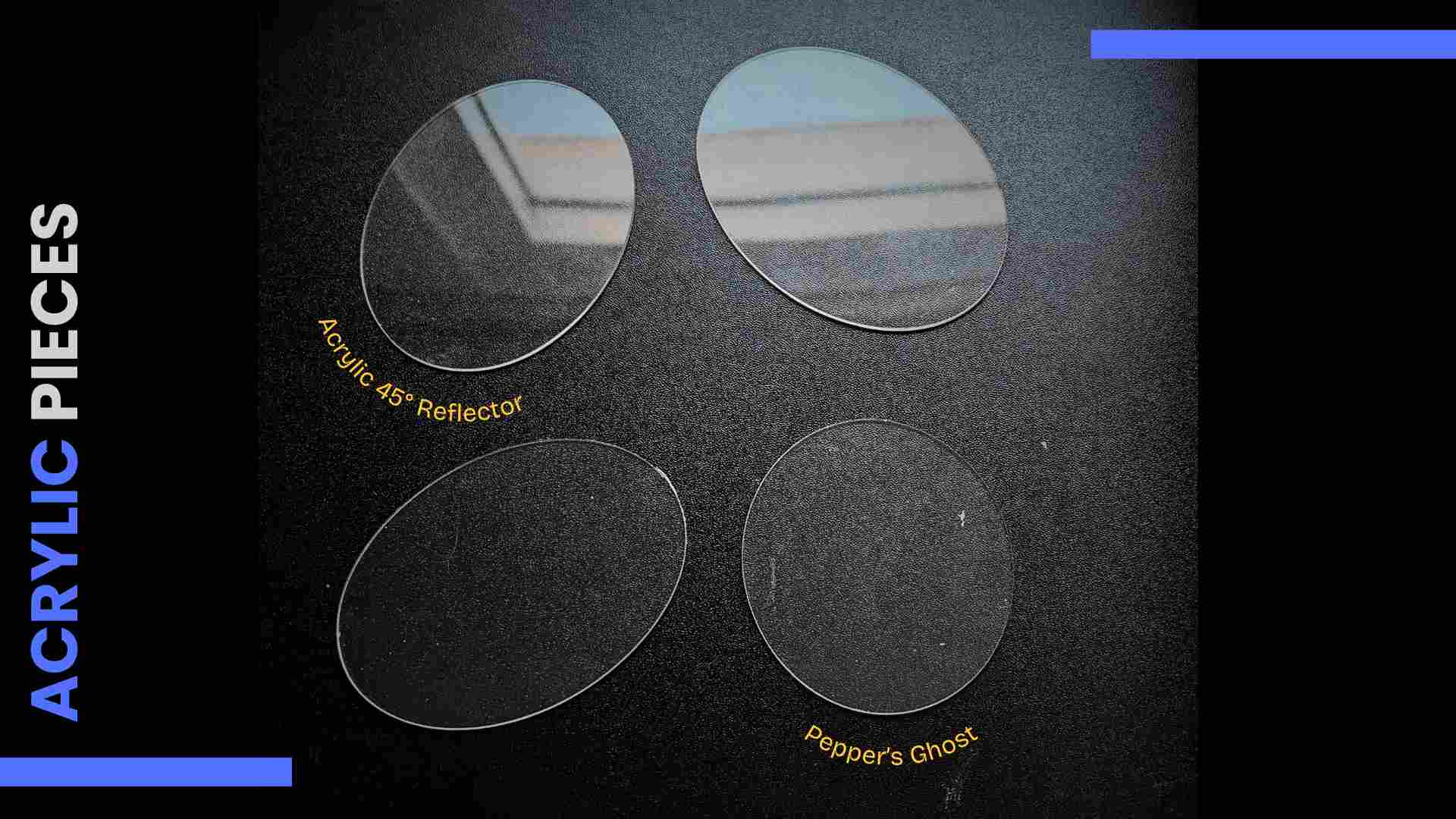
Acrylic Reflector
0.2 mm clear acrylic for insertion into a glass (Pepper's Ghost Holographic System)
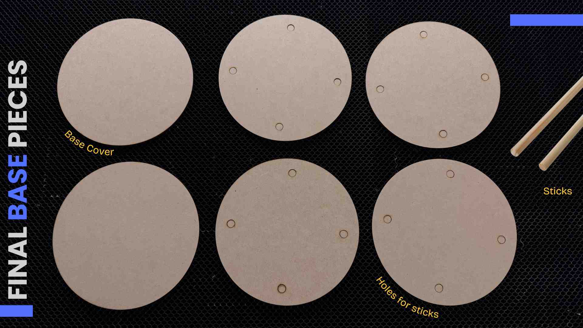
MDF Base
3mm MDF. Base with wooden sticks for the lamp. Covered with two strips of wood veneer.
✦ Process Reflection
Getting the acrylic reflector angle right took three test cuts. The 45° angle needs to be exact, even 2° off visibly shifts the projected image out of alignment with the chamber center.
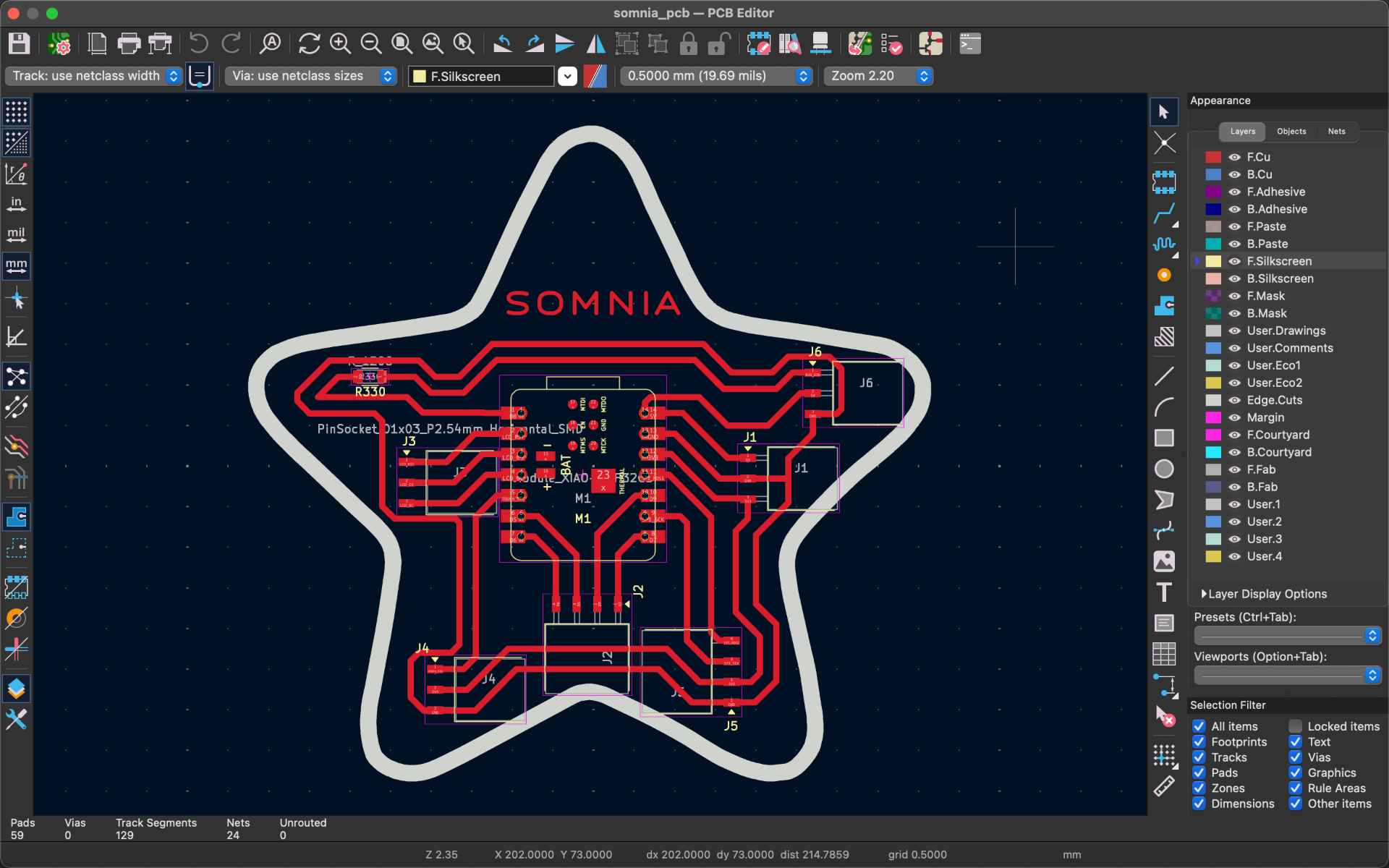
✦ Designing the PCB
The custom PCB was designed in KiCad and milled on the Roland SRM-20 at Fab Lab Puebla. The board routes all connections from the XIAO ESP32-C6 to the four subsystems: GC9A01 display, NeoPixel ring, TTP223 touch sensor and 5V 2A power supply. For detailed PCB design and fabrication documentation, go see my Week 6 and Week 8.
✦ Schematic in KiCad
The custom PCB is built around a Seeed XIAO ESP32-C6 and connects the lamp’s main subsystems: the TTP223 touch sensor, the NeoPixel ring and the GC9A01 holographic display.
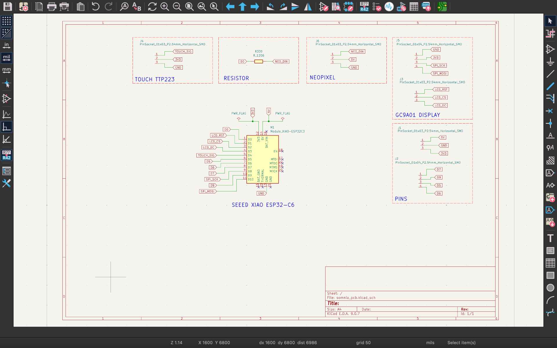
- ◆1 Seed XIAO ESP32-C6
- ◆1 Resistor SMD (330Ω)
- ◆13 Male Header Pins
- ◆14 Female Header Pins
✦ PCB Layout
The PCB was designed in a custom star-shaped form with the Seeed XIAO ESP32-C6 located at its center, with the components arpund it, while 0.8 mm traces provide reliable routing and fabrication. I also added the project's name on it.
✦ Pin Mapping — XIAO ESP32-C6
| Component | Signal | XIAO Pin | GPIO | Notes |
|---|---|---|---|---|
| GC9A01 Display | SCL / SCK | D8 | GPIO19 | SPI clock |
| GC9A01 Display | SDA / MOSI | D10 | GPIO18 | SPI data |
| GC9A01 Display | CS | D2 | GPIO2 | Chip select |
| GC9A01 Display | DC | D3 | GPIO21 | Data / command |
| GC9A01 Display | RST | D1 | GPIO1 | Power |
| GC9A01 Display | VCC | 3.3V | - | Reset |
| NeoPixel Ring | DIN | D0 | GPIO0 | WS2812B data in |
| TTP223 Touch | SIG | D4 | GPIO22 | Digital input |
| NeoPixel Ring | VCC | 5V | - | Power |
| GC9A01 / TTP223 | VCC | 3.3V | - | Power |
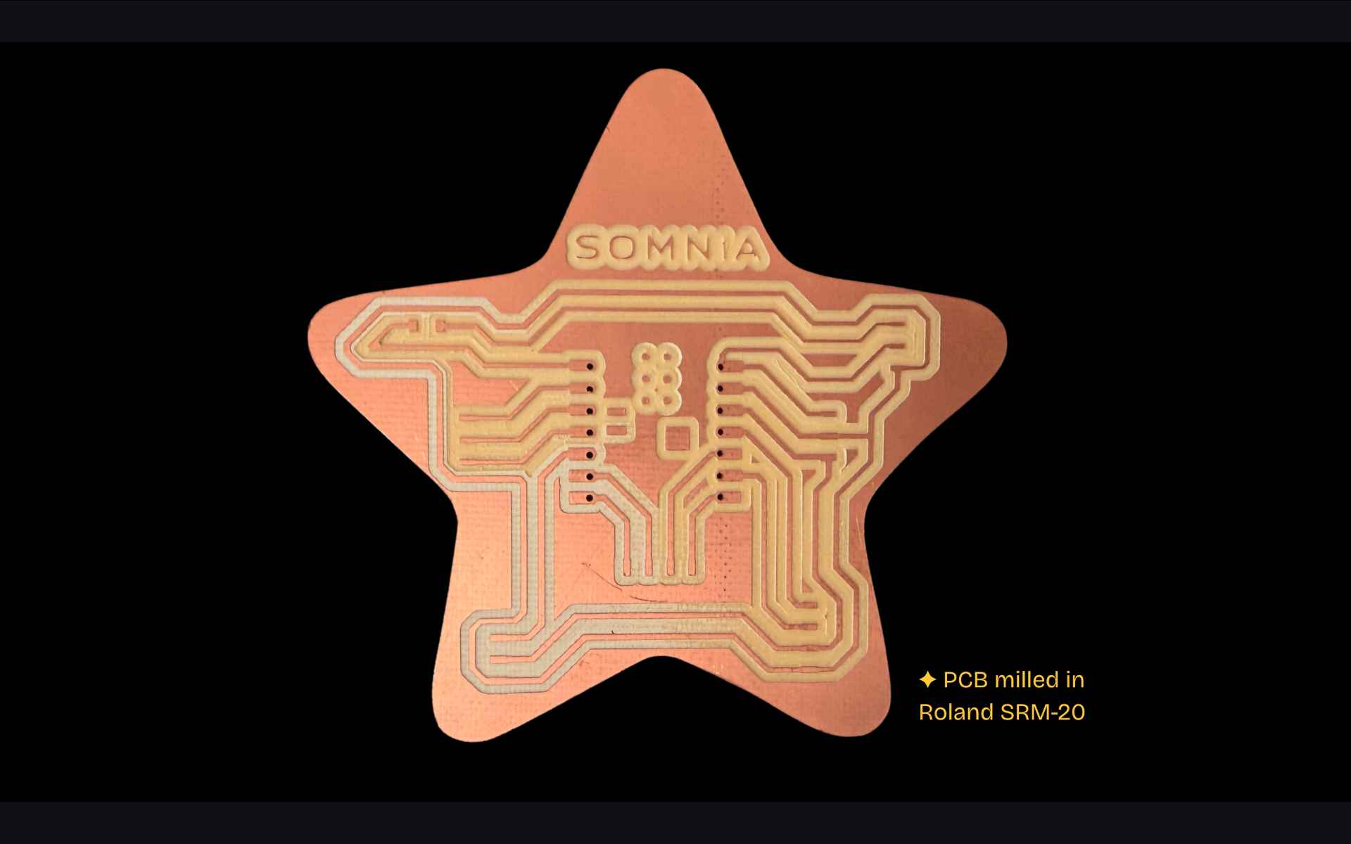
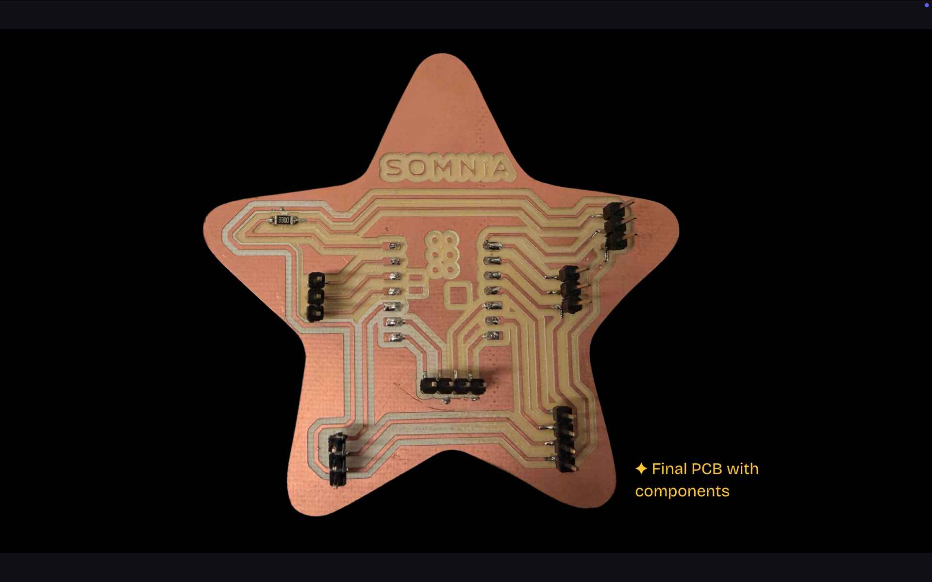
✦ PCB Reflection
The PCB was designed using Gerber2png and modsproject, then printed on a Roland SMR-20 and finally soldered with the required components. For more information, see my Week 8.
✦ Display Selection
I selected a 1.28" GC9A01 circular display to generate the visuals for the Pepper's Ghost system. Although I initially referred to it as an OLED, I later discovered it is actually a TFT LCD display that communicates via SPI (MOSI and SCK signals) and operates at 3.3V, making it directly compatible with the XIAO ESP32-C6.
✦ First Hardware Issue
The display was first connected on a breadboard (just as a test) using the hardware SPI pins of the XIAO ESP32-C6. During the first power-up test, I accidentally created a short circuit that caused both the jumper wires and the display to heat up. Fortunately, the short circuit was only momentary and the display didn't suffered permanent damage.
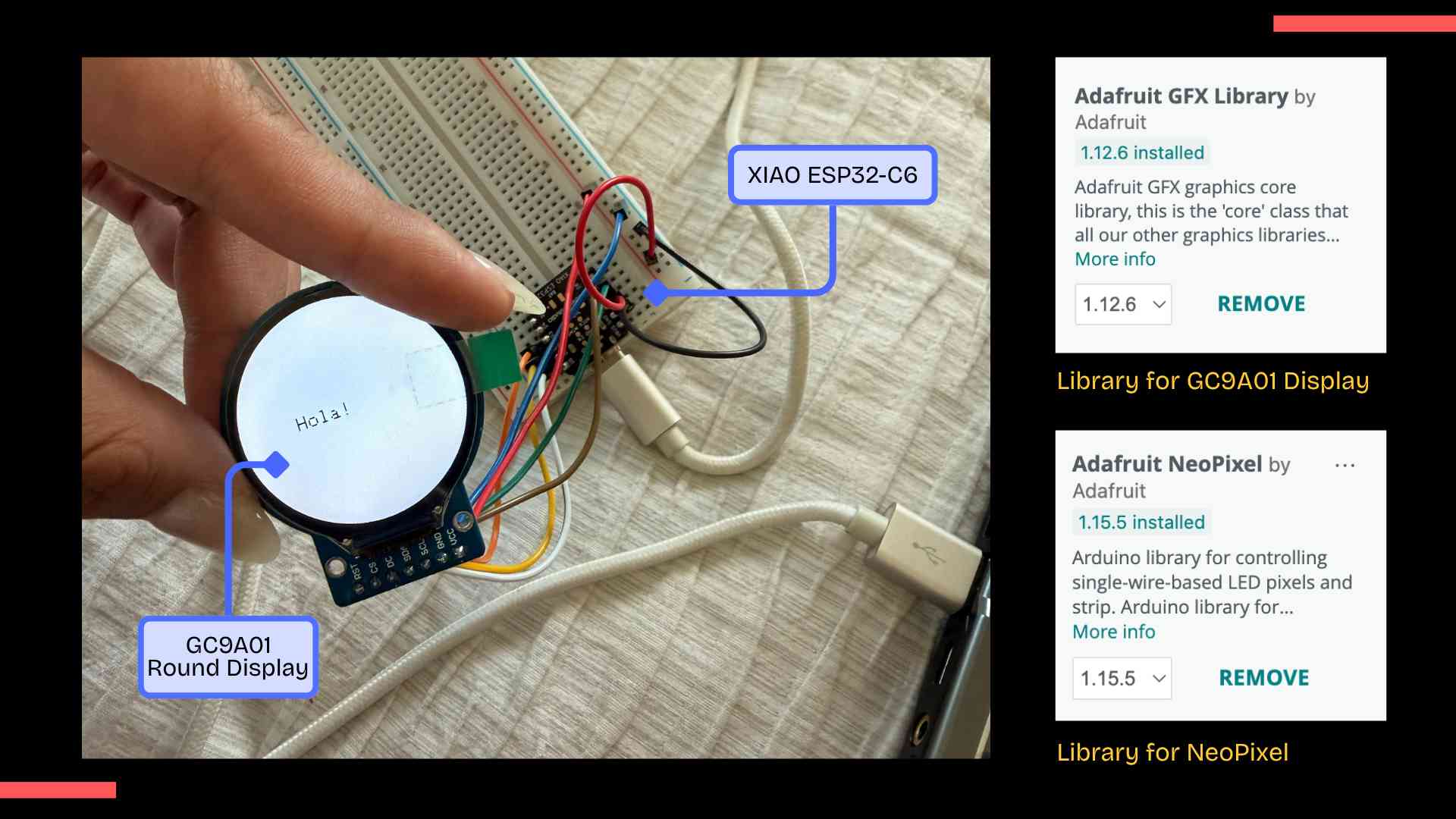
Library Selection
I first tried using TFT_eSPI, but it wasn't compatible with the MCU and generated compilation errors. I then switched to the Arduino GFX Library, which supports the GC9A01 and displayed graphics on the screen.
✦ Preparing Graphics for the Display
To create the holographic content, I designed three graphics in Procreate using a completely black background. This was important because only the bright elements should remain visible when reflected by the Pepper's Ghost system.
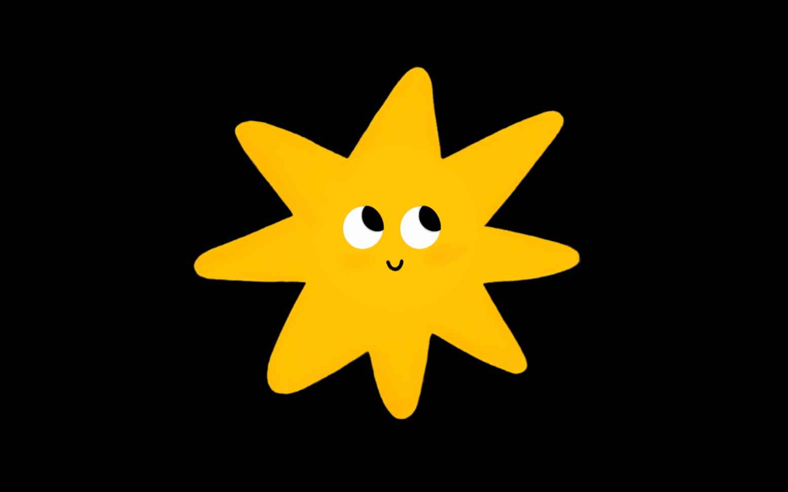
✦ Dream Star
A playful star that accompanies children during quiet nighttime moments.

✦ Dream Moon
A gentle moon that helps create a relaxing and comforting atmosphere.
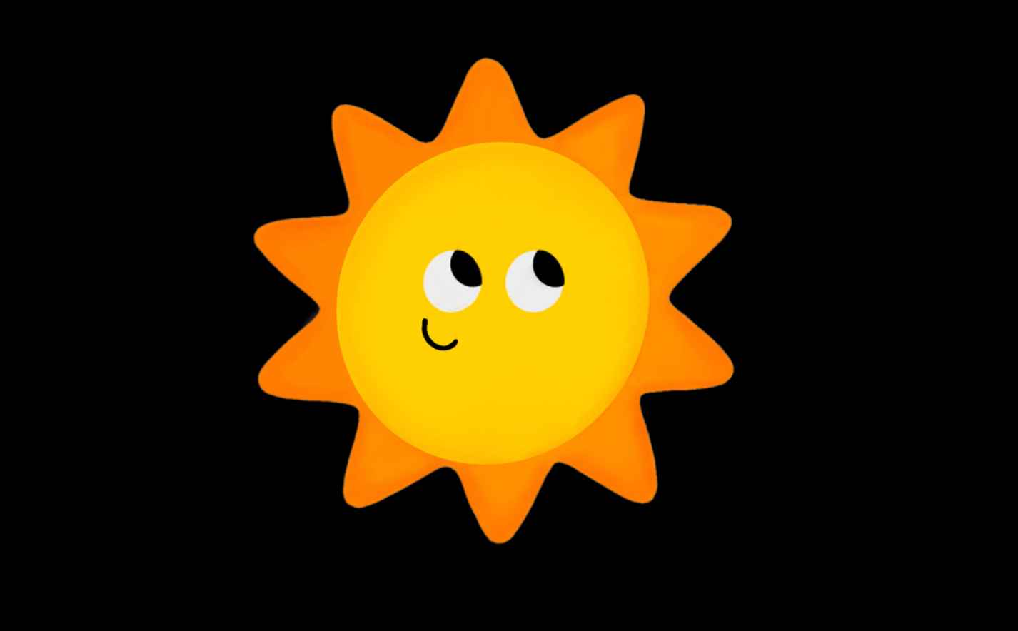
✦ Dream Sun
A warm sun that brings a feeling of happiness and safety to the experience.
✦ Final Resolution
The final graphics were resized to 200 × 200 pixels, which preserved visual quality while keeping memory usage within the limits of the microcontroller.
✦ Image Conversion Workflow
The GC9A01 display cannot directly read PNG or JPG images, so every graphic needed to be converted into RGB565 arrays stored inside the Arduino program (file.h).
I experimented with different online conversion tools, including LVGL Image Converter and FileToCArray. While both tools generated usable files, they still required additional manual modifications.
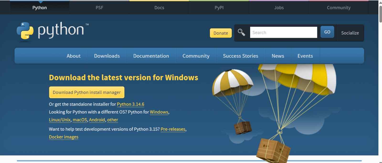
01. Download Python
Go to python.org/downloads and download the Python installer for Windows.
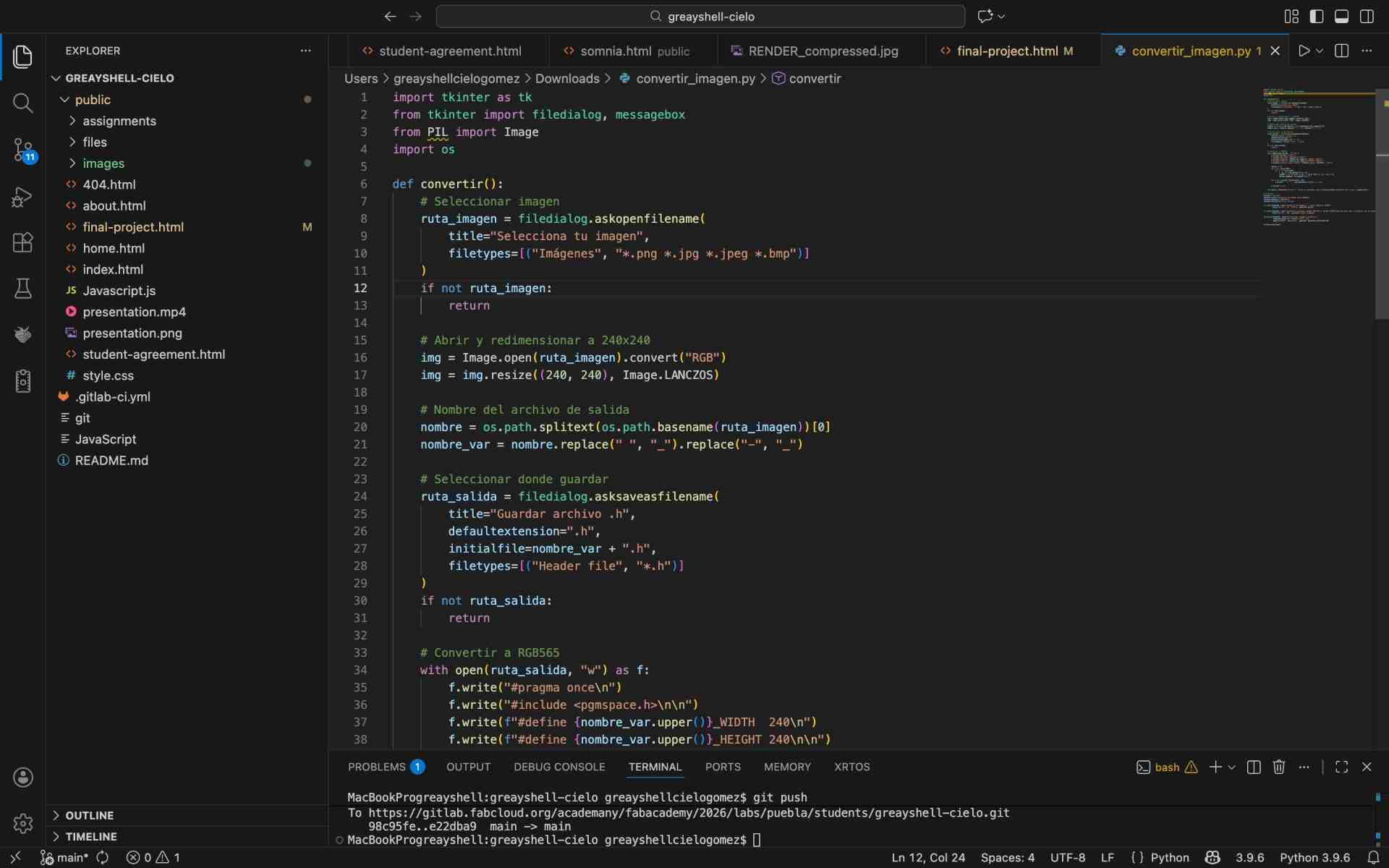
02. Download the Conversion Script
Since I needed a way to convert images to the RGB565 format required by the display, I asked Claude to generate a custom
Python script for me. The script convertir_imagen.py opens a graphical window that lets you select any image, automatically
resizes it and converts it to a .h header file ready to use in Arduino.
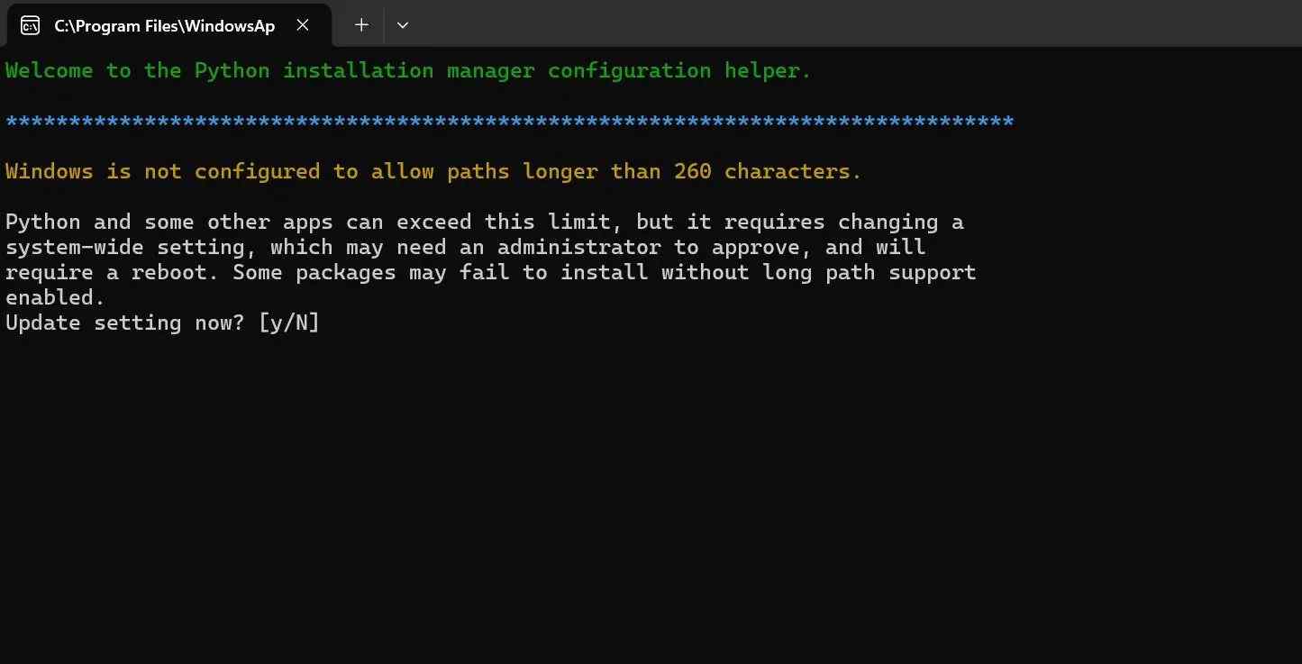
03. Run the Installer
During installation the terminal asked about enabling long path support in Windows. I typed y to accept [Y], which is recommended for Python to work properly.
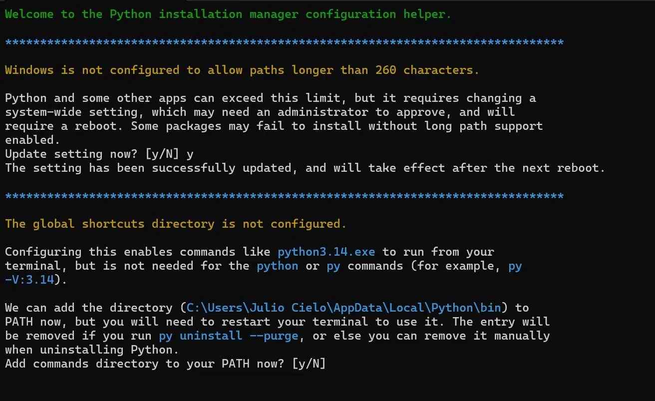
04. Add Python to PATH
It also asked to add Python to the system PATH so I could run it from any terminal window. I accepted this one too.
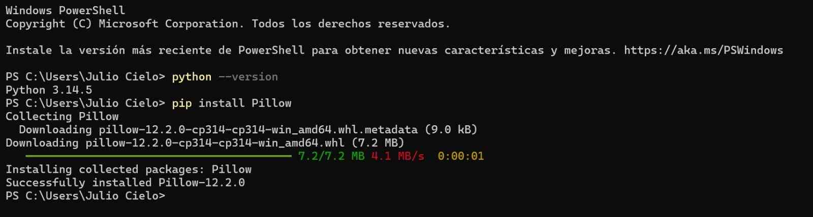
05. Verify Installation and Install Pillow
Once installed I ran python --version to make sure everything worked, then installed Pillow with pip install Pillow, that is the library the script needs to process images.
06. Navigate to the Script and Run It
I saved the script to my Desktop, navigated to that folder in PowerShell and ran python convertir_imagen.py to launch it.

07. Graphical Interface Opens
Then a green window opened with a button to select the image that I wanted to convert.
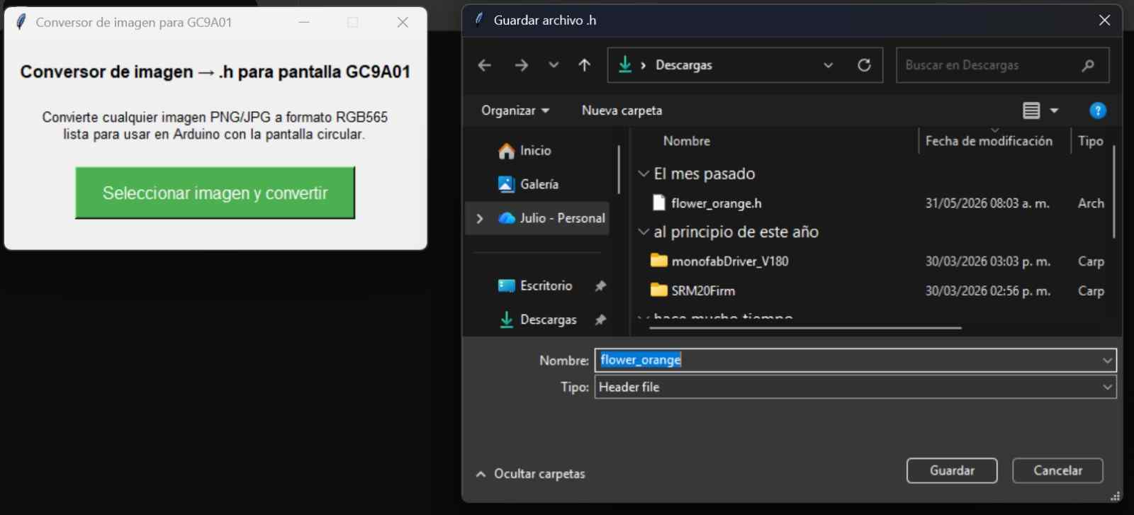
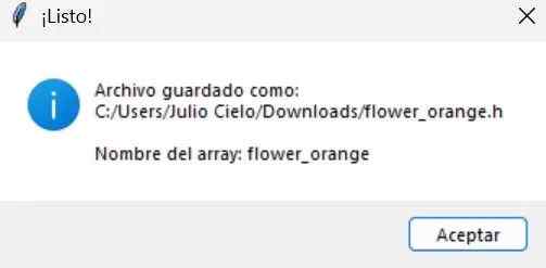
08. Image Converted
After selecting the image I prepared at 240x240px, the script generated a .h file with the image encoded in RGB565 format, ready to include in Arduino.
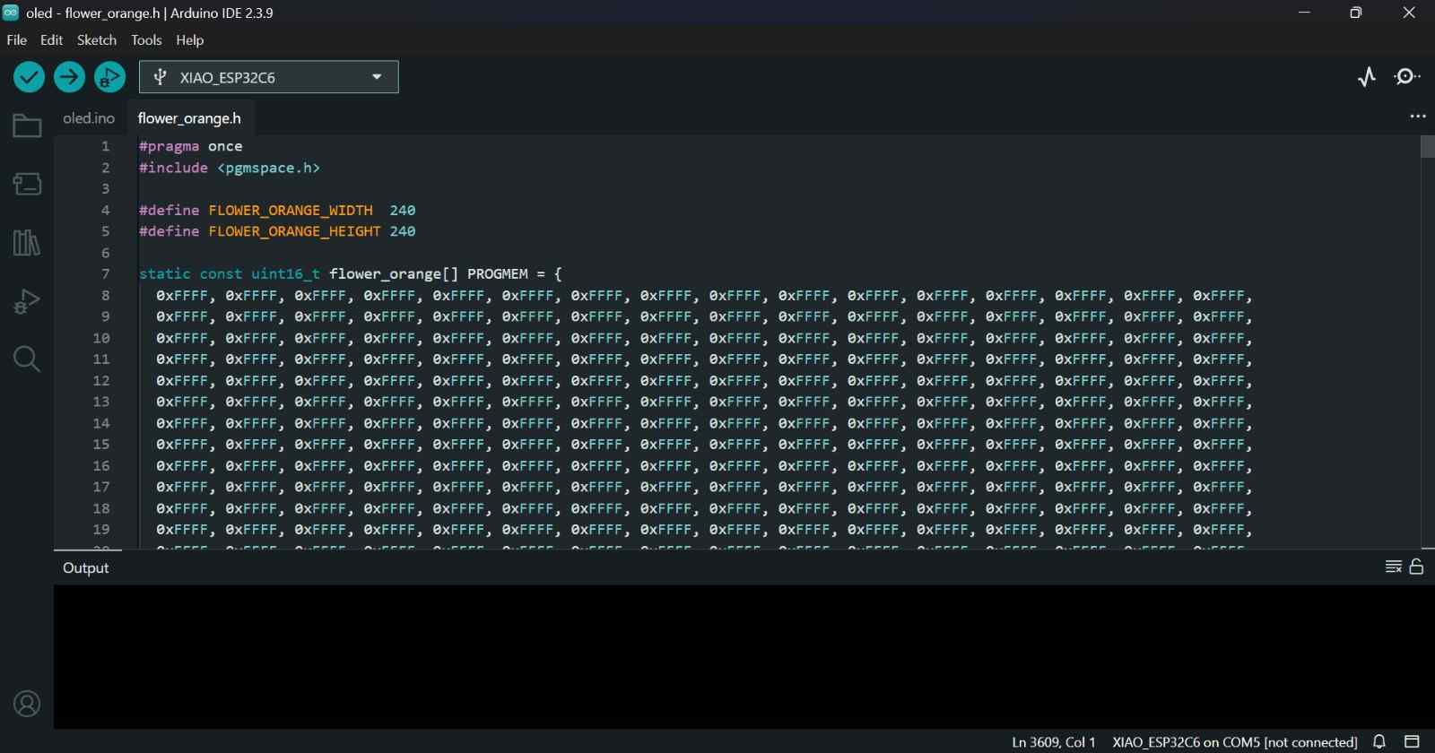
09. Select and Convert the Image
I copied the .h file to the sketch folder and it showed up as a new tab in Arduino IDE.
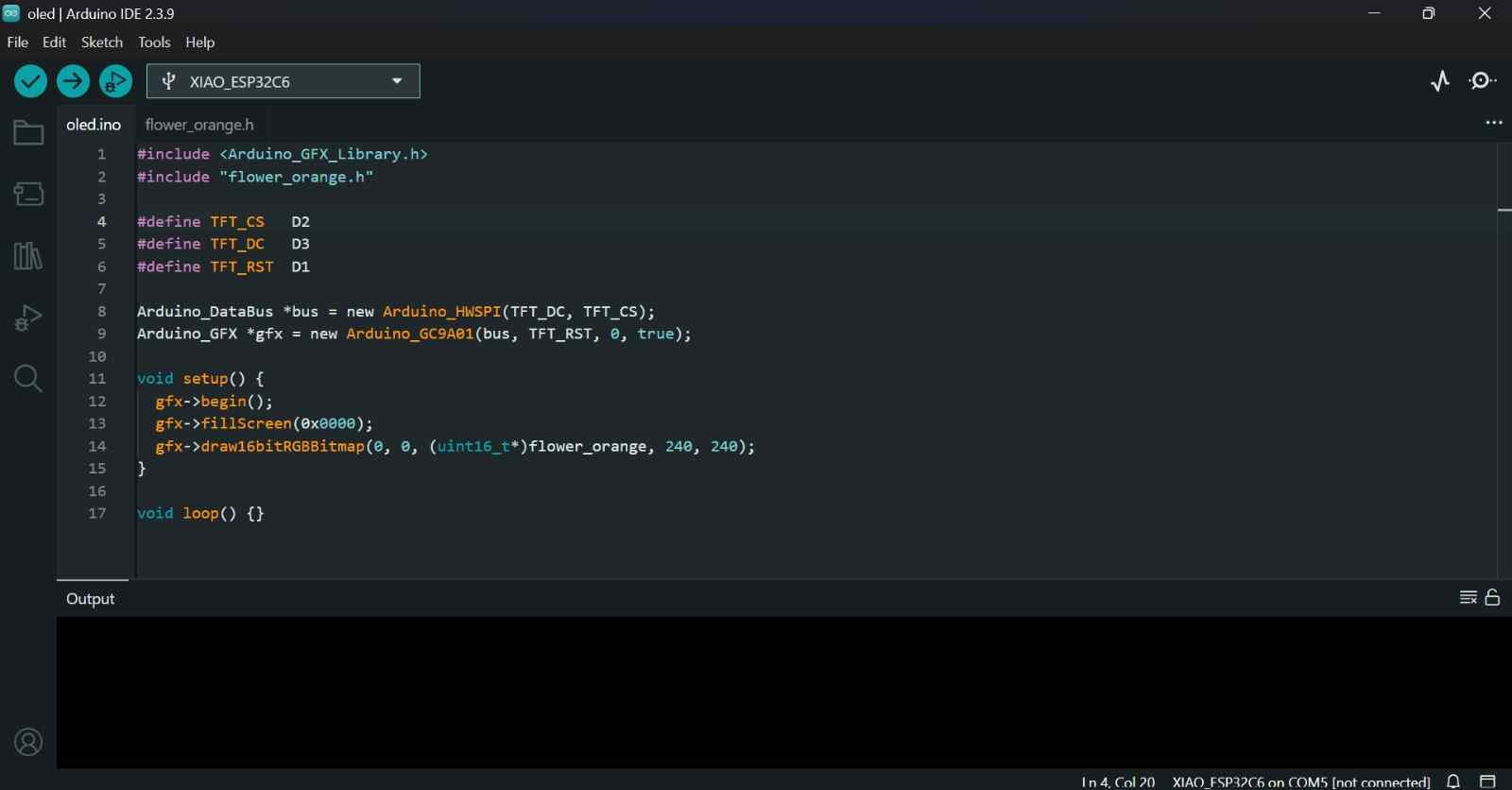
10. Arduino IDE
Then in a New Sketch I used draw16bitRGBBitmap() to display it on screen.
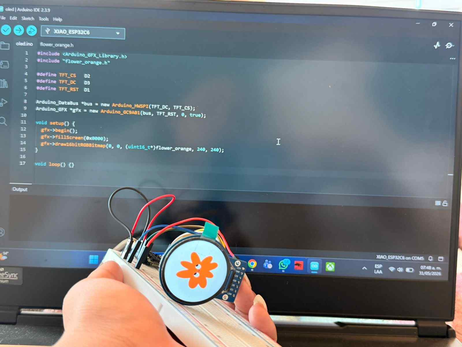
11. Result on Screen
The image appeared on the GC9A01 display with the image.
✦ Arduino Code C++
This was the code used to program the screen to project the example image.
#include <Arduino_GFX_Library.h> // Library for the GC9A01 display
#include "flower_orange.h" // Converted image stored as RGB565 array
#define TFT_CS D2 // Chip Select pin
#define TFT_DC D3 // Data/Command pin
#define TFT_RST D1 // Reset pin
// Create the SPI communication bus
Arduino_DataBus *bus = new Arduino_HWSPI(TFT_DC, TFT_CS);
// Initialize the GC9A01 display
Arduino_GFX *gfx = new Arduino_GC9A01(bus, TFT_RST, 0, true);
void setup() {
gfx->begin(); // Start the display
gfx->fillScreen(0x0000); // Clear screen with black background
// Draw the image at position (0,0)
gfx->draw16bitRGBBitmap(
0,
0,
(uint16_t*)flower_orange,
240,
240
);
}
void loop() {
// No repeated actions required
}
✦ Conversion Script
This custom Python tool converts images into RGB565 format and generates Arduino-ready .h files, making it easier to display custom graphics on the GC9A01 screen.
import tkinter as tk # Create the graphical interface
from tkinter import filedialog, messagebox
from PIL import Image # Open and edit images
import os # Handle file names and paths
def convert_image():
# Select an image file
image_path = filedialog.askopenfilename(
title="Select an image",
filetypes=[("Images", "*.png *.jpg *.jpeg *.bmp")]
)
if not image_path:
return
# Open image and convert it to RGB
img = Image.open(image_path).convert("RGB")
# Resize image to fit the display resolution
img = img.resize((240, 240), Image.LANCZOS)
# Generate a valid variable name
file_name = os.path.splitext(os.path.basename(image_path))[0]
variable_name = file_name.replace(" ", "_").replace("-", "_")
# Choose where to save the output file
output_path = filedialog.asksaveasfilename(
title="Save .h file",
defaultextension=".h",
initialfile=variable_name + ".h",
filetypes=[("Header file", "*.h")]
)
if not output_path:
return
# Create the header file
with open(output_path, "w") as f:
# Write file header information
f.write("#pragma once\n")
f.write("#include <pgmspace.h>\n\n")
f.write(f"#define {variable_name.upper()}_WIDTH 240\n")
f.write(f"#define {variable_name.upper()}_HEIGHT 240\n\n")
# Create RGB565 image array
f.write(f"static const uint16_t {variable_name}[] PROGMEM = {{\n")
values = []
# Convert every pixel to RGB565 format
for y in range(240):
for x in range(240):
r, g, b = img.getpixel((x, y))
rgb565 = (
((r & 0xF8) << 8)
| ((g & 0xFC) << 3)
| (b >> 3)
)
values.append(f"0x{rgb565:04X}")
# Write pixel values into the array
for i in range(0, len(values), 16):
f.write(" " + ", ".join(values[i:i+16]) + ",\n")
f.write("};\n")
# Show confirmation message
messagebox.showinfo(
"Done!",
f"File saved as:\n{output_path}\n\nArray name: {variable_name}"
)
# Create application window
window = tk.Tk()
window.title("GC9A01 Image Converter")
window.geometry("400x200")
window.resizable(False, False)
# Title label
tk.Label(
window,
text="Image to .h Converter for GC9A01",
font=("Arial", 12, "bold"),
pady=20
).pack()
# Description label
tk.Label(
window,
text="Convert PNG or JPG images into RGB565 format\nfor Arduino and the GC9A01 display.",
font=("Arial", 10),
justify="center"
).pack()
# Conversion button
tk.Button(
window,
text="Select Image and Convert",
command=convert_image,
font=("Arial", 12),
bg="#4CAF50",
fg="white",
padx=20,
pady=10
).pack(pady=20)
# Run the application
window.mainloop()
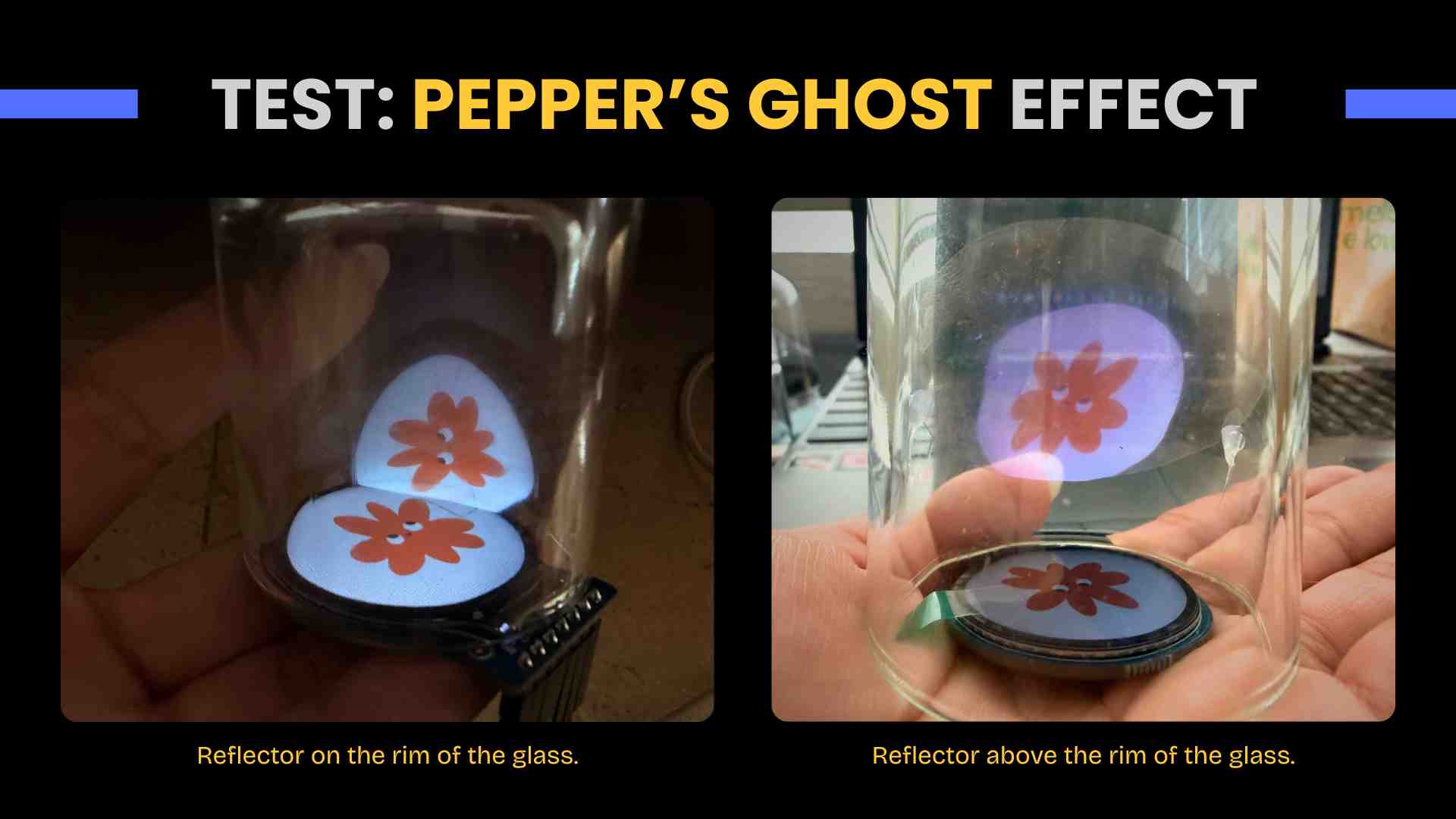
✦ Pepper's Ghost Effect Test
After generating the image, I made some quick prototypes to create the Pepper's Ghost effect using acetate and a small glass. In my first attempt, I placed the acetate at a 45-degree angle and above the rim of the glass, but this prevented the floating effect. I then decided to raise the acetate, and that's how I achieved the desired effect.
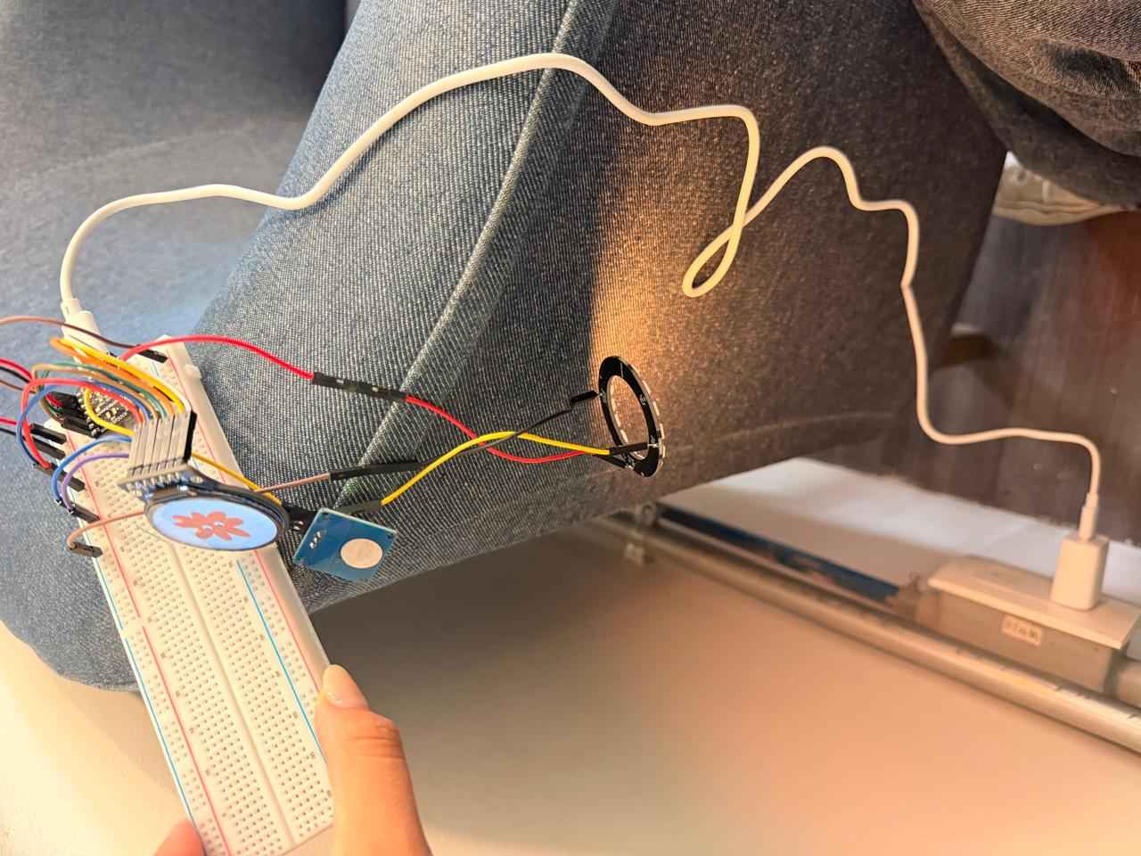
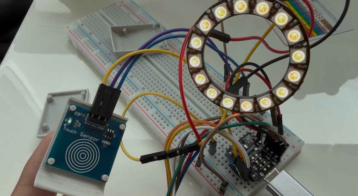
✦ Components Integration
Once the individual components were working independently, I connected the entire system on a breadboard to verify that all modules could operate together. This included the XIAO ESP32-C6, the GC9A01 display, the NeoPixel ring and the TTP223 touch sensor.
✦ Power Distribution
To simulate the final operating conditions, the system was powered using a 5V 2.4A wall adapter (Type C charger) connected directly to the XIAO ESP32-C6.
✦ PCB Integration
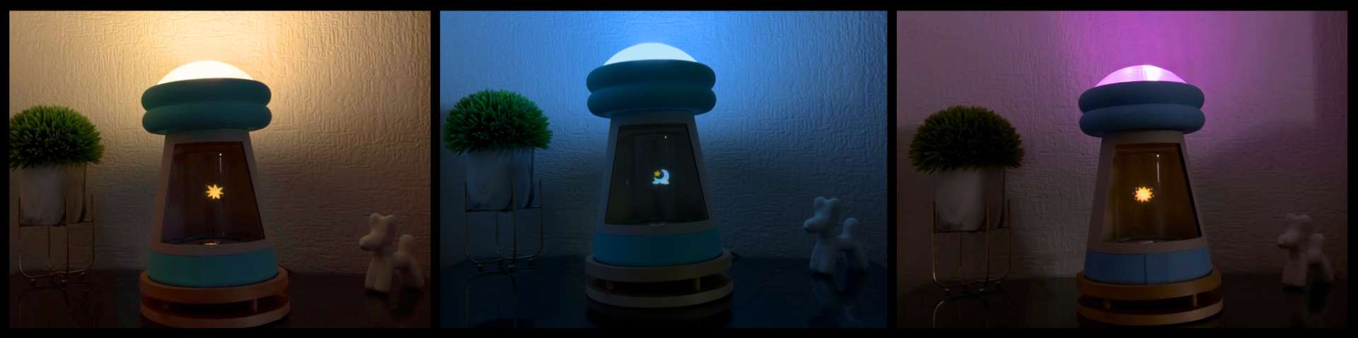
After validating the circuit on the breadboard, the components were transferred to the custom PCB. The lamp was programmed with the three designed images, plus three light modes in addition to white: yellow-orange, blue-purple, pink-white, which change with long touches on the sensor. Turning the whole system on/off is done with a subtle touch.
✦ Interface + MQTT Communication + GitLab
To enable communication between the lamp and the web interface, I implemented an MQTT-based system using the public HiveMQ broker. This architecture allows the ESP32-C6 and the dashboard to exchange information in real time through dedicated topics. For the initial interface concept and design reference, see my Week 11.
01. Broker Selection
To establish communication between the ESP32 and the web interface, I selected broker.hivemq.com, a free public MQTT broker. This option simplified the development process because it didn't require additional installation, server configuration or user registration.
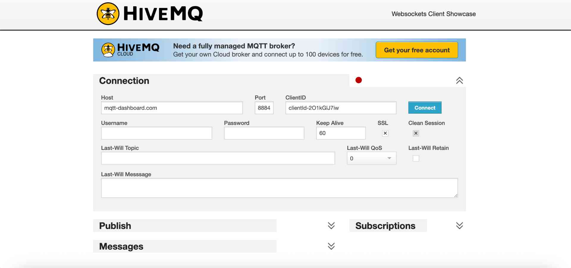
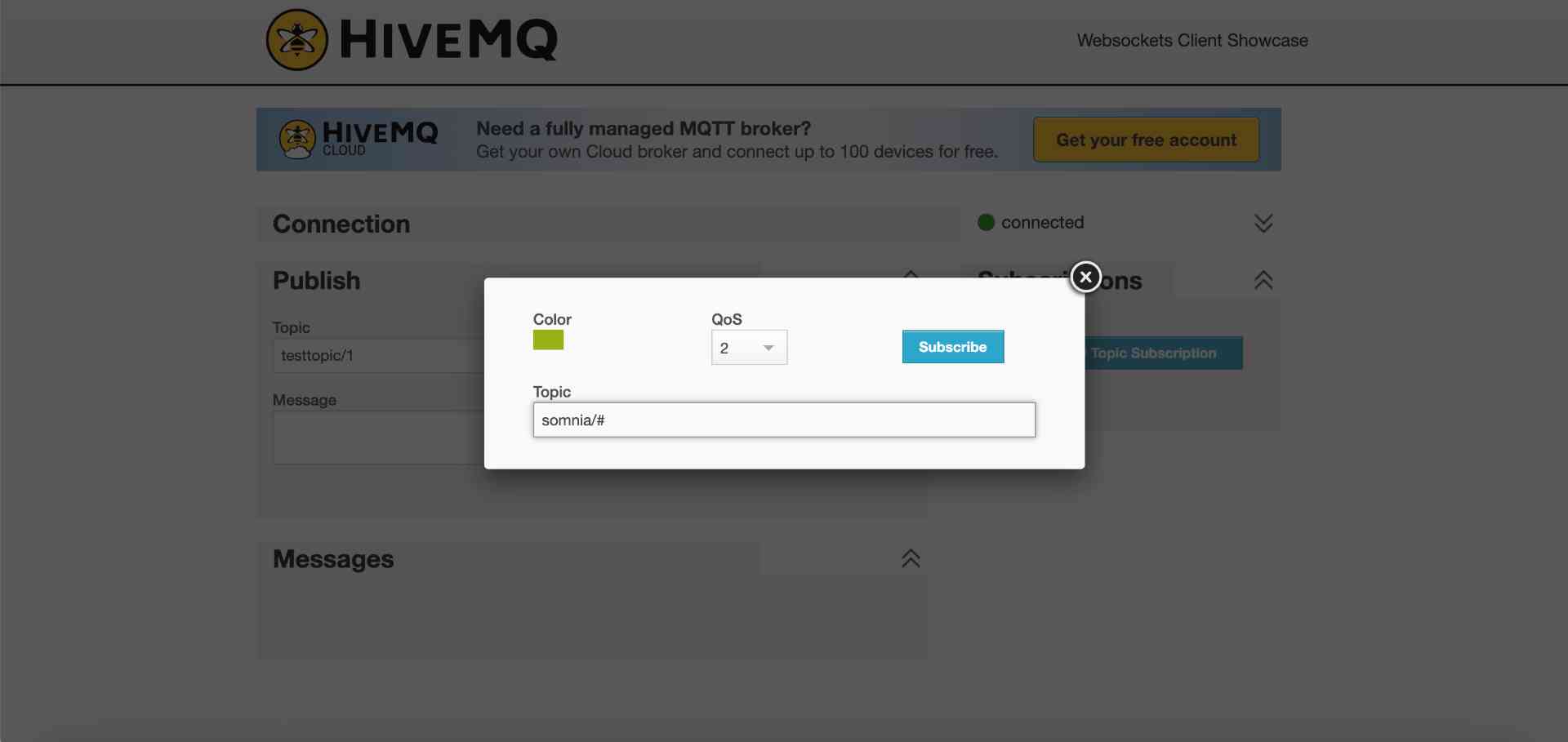
02. Subscribing somnia/#
Before integrating the dashboard, I tested the MQTT communication directly from the HiveMQ WebSocket Client. By subscribing to the wildcard topic somnia/#, I was able to monitor all messages related to the project.
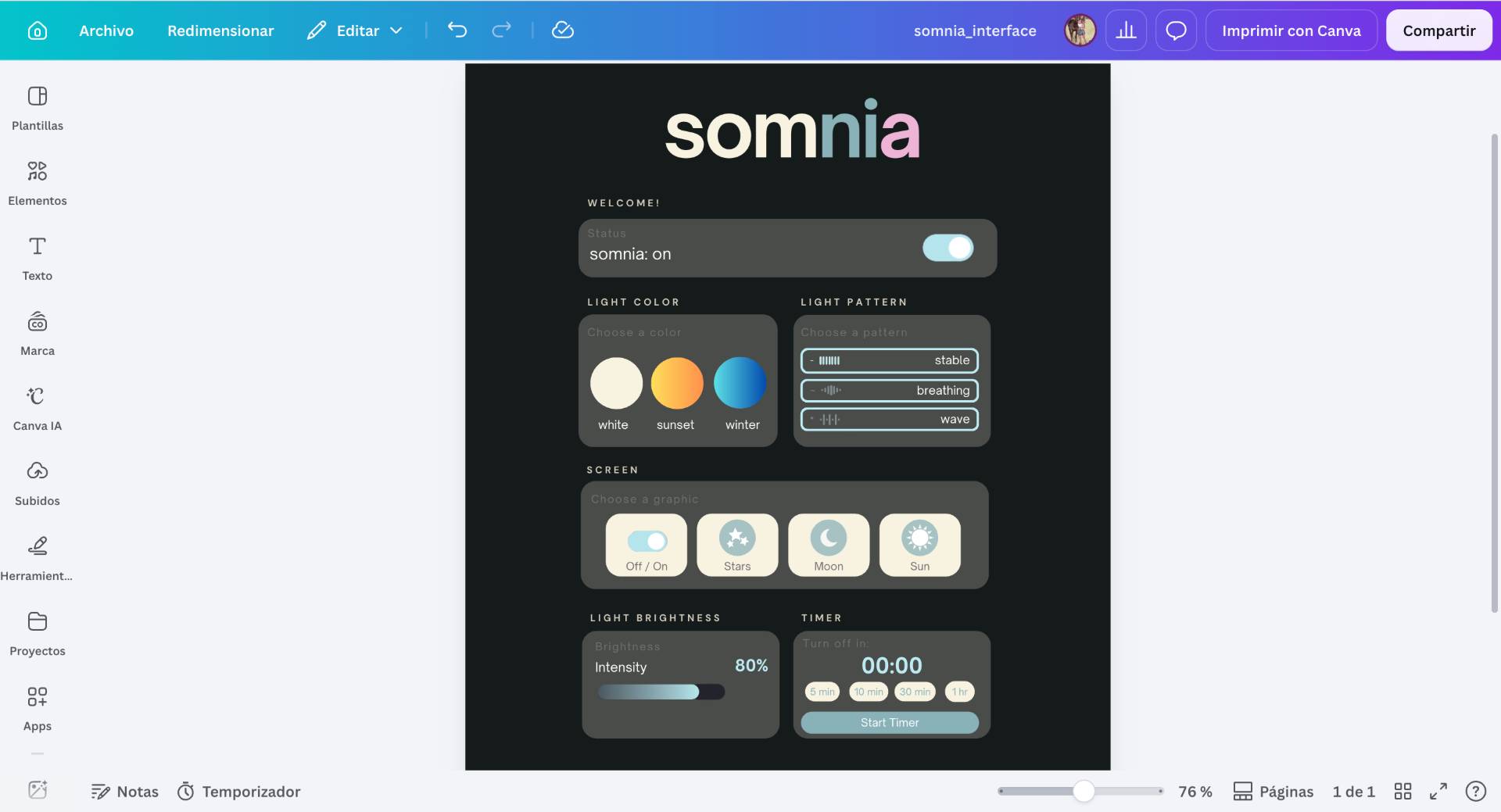
03. Interface Design
Then I started designing the interface in Canva, to distribute the commands and functions in an orderly and intuitive way.
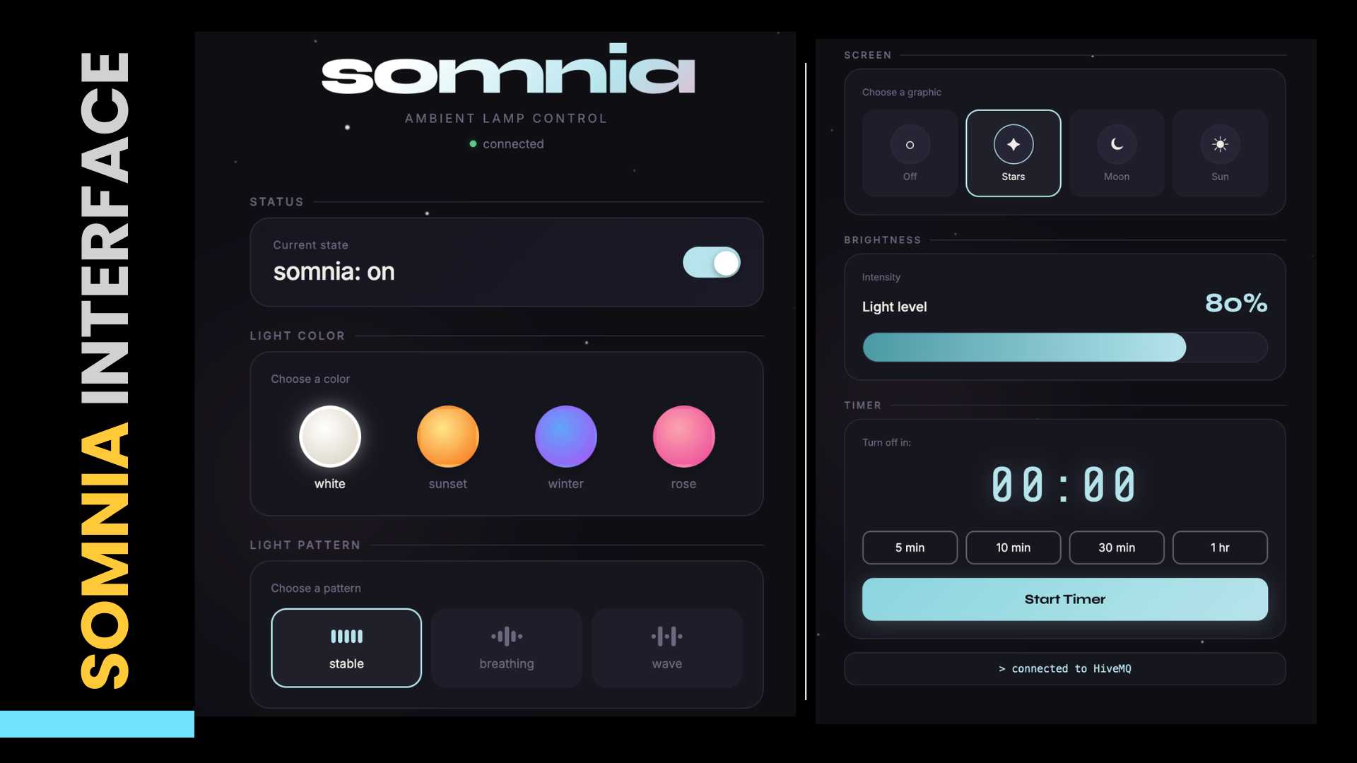
04. Somnia's Final Interface
To continue with the development of the web interface, I asked Claude to help me develop the HTML using my design as a guide.
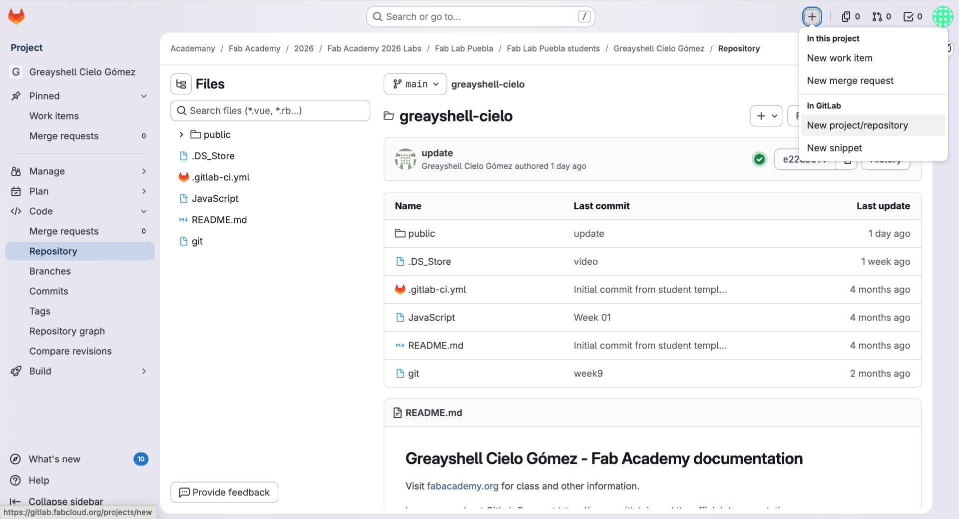
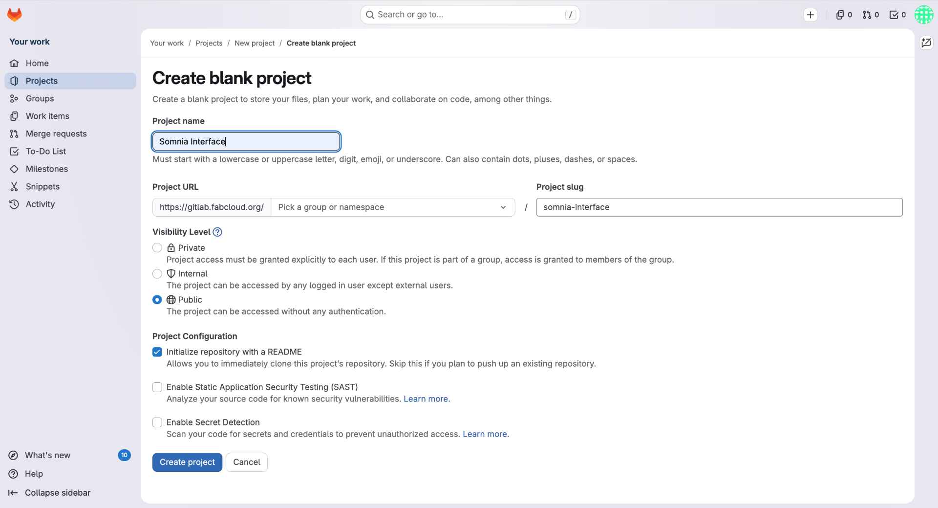
05. Creating a New GitLab Repository
To host the web dashboard separately from my Fab Academy documentation, I created a new repository in GitLab. From the repository page, I selected New Project/Repository and created a blank project called Somnia Interface.
06. Configuring GitLab Pages
I saved the script to my Desktop, navigated to that folder in PowerShell and ran python convertir_imagen.py to launch it.
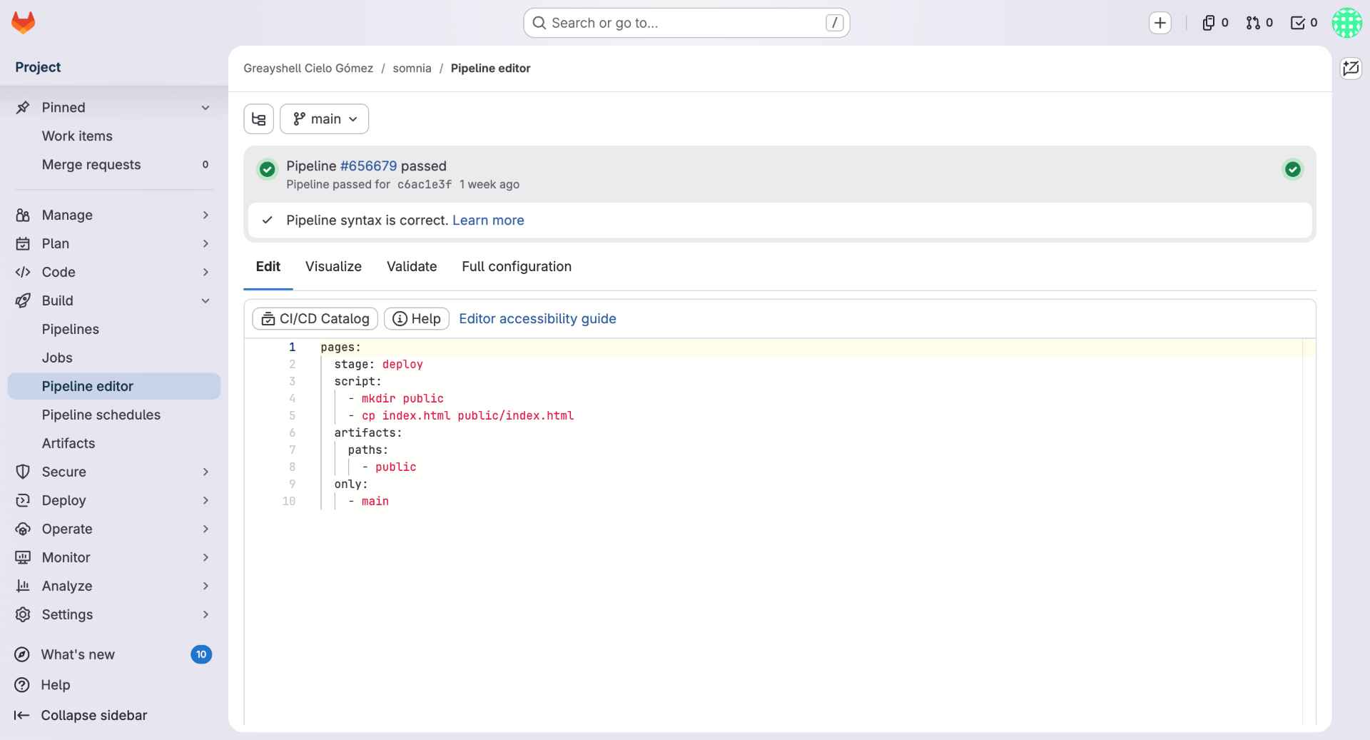
07. Configuring GitLab Pages
Then, I configured GitLab Pages by creating a .gitlab-ci.yml file. This file automatically moves the website files into the public folder and publishes them whenever changes are pushed to the main branch. Once the pipeline passed, GitLab Pages generated a public URL for the interface: somnia-interface .
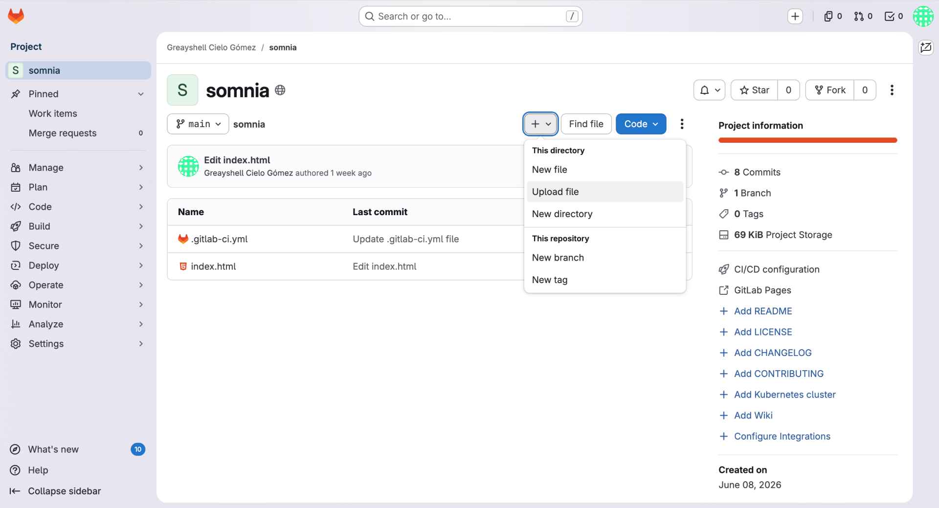
08. Uploading the HTML File
I uploaded the website file (html) directly through the GitLab interface. The main file, index.html, contained the complete html, including the MQTT connection, user interface, styling and control buttons.
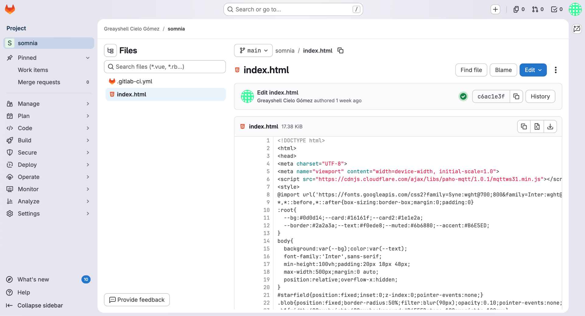
09. Verifying the Published Website
Finally, I opened the uploaded index.html file to verify that all changes had been saved correctly. This step allowed me to confirm that the dashboard code was available in the repository
✦ Somnia's HTML + URL
This was the code used to program the screen to project the example image. Click here to go to the web page: somnia-interface.
<style> /* Import custom fonts */ @import url('https://fonts.googleapis.com/css2?family=Syne:wght@700;800&family=Inter:wght@300;400;500&display=swap'); /* Main color palette */ :root{ --bg:#0d0d14; --card:#16161f; --text:#f0ede8; --muted:#6b6880; --accent:#B6E5ED; } /* General page styling */ body{ background:var(--bg); color:var(--text); font-family:'Inter',sans-serif; } /* Somnia title */ .title{ font-family:'Syne',sans-serif; font-size:60px; background:linear-gradient(135deg,#fff 30%,#B6E5ED 70%,#f4a7c3); -webkit-background-clip:text; -webkit-text-fill-color:transparent; } /* Dashboard cards */ .card{ background:var(--card); border:1px solid #2a2a3a; border-radius:18px; padding:18px; } </style>
<script src="https://cdnjs.cloudflare.com/ajax/libs/paho-mqtt/1.0.1/mqttws31.min.js"></script>
var BROKER = 'broker.hivemq.com';
var PORT = 8884;
// Connect to the MQTT broker
function conectar(){
// Generate a unique client ID
var id = 'somnia' + Math.floor(Math.random()*9999);
// Create MQTT client
mqttClient = new Paho.MQTT.Client(BROKER, PORT, id);
mqttClient.connect({
// Execute when connection succeeds
onSuccess:function(){
// Subscribe to status topic
mqttClient.subscribe('somnia/estado');
},
// Enable secure connection
useSSL:true
});
}
function pub(topic,message){
var msg = new Paho.MQTT.Message(String(message));
msg.destinationName = topic;
mqttClient.send(msg);
}
function togglePower(){
encendida=!encendida;
pub('somnia/control',
encendida ? 'sol' : 'off');
}
function setColor(c){
pub('somnia/color',c);
}
function toggleTimer(){
timerInterval=setInterval(function(){
timerSegs--;
if(timerSegs<=0){
pub('somnia/control','off');
}
},1000);
}
✦ Final Result
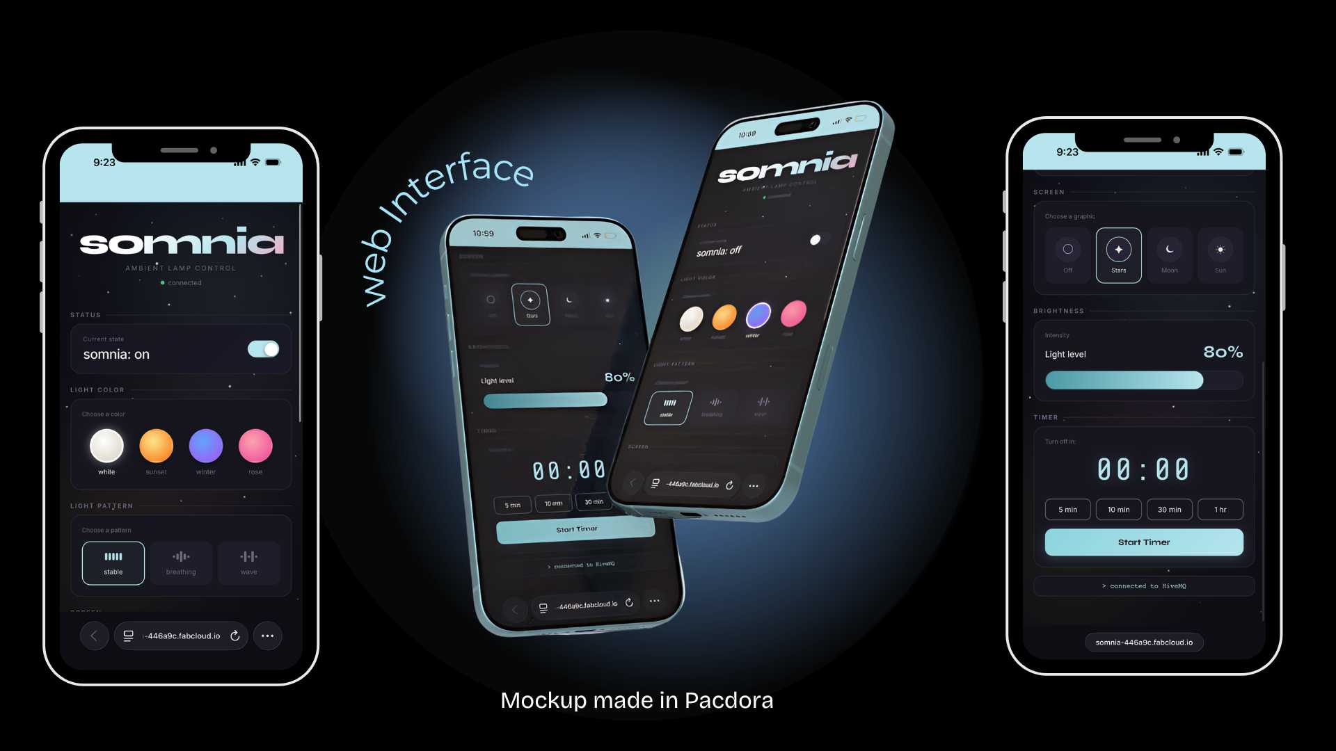
The final interface successfully integrates MQTT communication, wireless control, and visual design into a single platform.
/* SOMNIA - Main System Functions */
#include <WiFi.h> // WiFi connection
#include <PubSubClient.h> // MQTT communication
#include <Adafruit_NeoPixel.h> // NeoPixel LED control
#include <Arduino_GFX_Library.h> // GC9A01 display control
#include "moon.h" // Moon graphic
#include "star.h" // Star graphic
#include "sun.h" // Sun graphic
/* MQTT Message Handling */
void callback(char* topic, byte* payload, unsigned int length) {
String msg = "";
// Convert received message into a string
for (int i = 0; i < length; i++) {
msg += (char)payload[i];
}
String currentTopic = String(topic);
// Update selected color
if (currentTopic == "somnia/color") {
currentColor = msg;
}
// Update selected lighting pattern
if (currentTopic == "somnia/pattern") {
currentPattern = msg;
}
// Update selected holographic graphic
if (currentTopic == "somnia/display") {
currentScreen = msg;
previousScreen = "";
}
}
/* MQTT Broker Configuration */
// Configure HiveMQ broker
client.setServer(broker, 1883);
// Assign callback function
client.setCallback(callback);
/* Display Graphics */
void showImage(String imageName) {
// Clear display
gfx->fillScreen(0x0000);
// Show selected image
if (imageName == "moon") {
gfx->draw16bitRGBBitmap(
20, 20,
(uint16_t*)moon,
200, 200
);
} else if (imageName == "star") {
gfx->draw16bitRGBBitmap(
20, 20,
(uint16_t*)star,
200, 200
);
} else if (imageName == "sun") {
gfx->draw16bitRGBBitmap(
20, 20,
(uint16_t*)sun,
200, 200
);
}
}
/* Touch Sensor Interaction */
void handleTouch() {
bool touching = digitalRead(PIN_TOUCH);
// Detect first touch
if (touching && !touchDetected) {
touchStartTime = millis();
touchDetected = true;
}
// Detect touch release
if (!touching && touchDetected) {
unsigned long duration =
millis() - touchStartTime;
touchDetected = false;
// Short touch → ON / OFF
if (duration < 500) {
lampOn = !lampOn;
}
// Long touch → Change color
else {
colorIndex =
(colorIndex + 1) % 4;
currentColor =
colors[colorIndex];
}
}
}
/* Main Program Loop */
void loop() {
// Reconnect if MQTT is disconnected
if (!client.connected()) {
reconnect();
}
// Process MQTT messages
client.loop();
// Read touch sensor
handleTouch();
// Update display when graphic changes
if (
screenEnabled &&
currentScreen != previousScreen
) {
showImage(currentScreen);
previousScreen =
currentScreen;
}
// Stop if lamp is OFF
if (!lampOn) return;
// Execute selected lighting pattern
if (currentPattern == "solid") {
solidPattern();
}
else if (
currentPattern == "breathing"
) {
breathingPattern();
}
else if (
currentPattern == "wave"
) {
wavePattern();
}
}
✦ Programming Reflection
The most challenging part of this process was converting the graphics into a format compatible with the display. I also encountered memory limitations on the ESP32-C6, which required reducing the image resolution to fit within the available storage. Although this prevented me from implementing animations, it helped me better understand the hardware constraints and optimize the system. Overall, I am satisfied with the final result and what I learned throughout the process
✦ Putting It All Together
For detailed system integration documentation, go see my Week 15.
Step 01
Base Assembly
PCB mounted on a lamp base. USB-C cable routed through the base. Touch sensor fixed to the front face.
Step 02
Display + Reflector Mounting
GC9A01 placed on its printed mount centered below the camera. Acrylic reflector bent at 45° inside a glass beaker. Neopixel cables run up behind the lamp body wall.
Step 03
NeoPixel Ring + Structural Rings
NeoPixel rings pass through the top rings and snap into the circular base.
Step 04
Dome + Final Closure
Translucent dome placed on top. Final functional test: touch to power on, cycle through modes, verify WiFi connectivity, confirm hologram projection alignment.
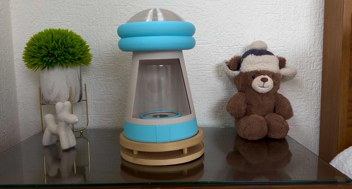
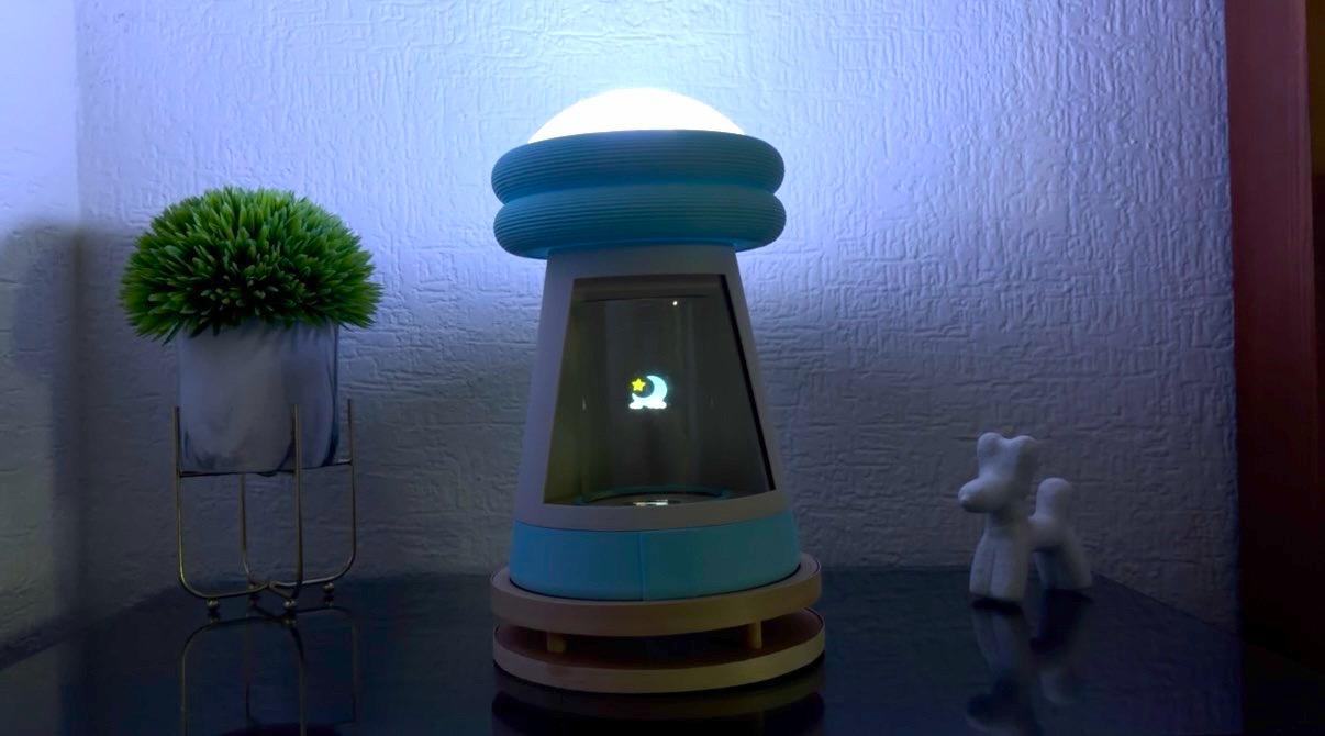
✦ Gallery
Below are images of the final result of somnia.
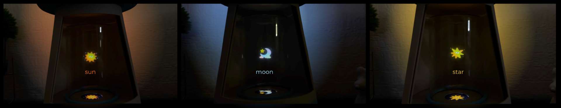
Subsystem 01
GC9A01 Hologram Visual
The display renders static image. *Text was added to indicate the image names.
Subsystem 02
NeoPixel Color Modes
Three color modes cycle on each touch event besides white (default): warm yellow to orange, cool blue to purple and pink to white. It integrates a gentle breathing so the lamp always feels alive.
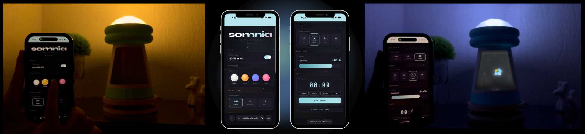
Subsystem 03
WiFi Web Interface
The ESP32-C6 serves a web interface on its local network exposing light mode selector and hologram static image switcher.
✦ What worked well
The Pepper’s Ghost effect worked successfully, creating a convincing floating visual. The integration between the lighting system, display, touch sensor and web interface also worked well, allowing the lamp to be controlled as a complete interactive system.
✦ What I'd do differently
I would explore a more powerful microcontroller to support short animations and better visual content. This would expand the storytelling possibilities while maintaining a good system performance.
✦ Future Directions
Future versions of Somnia could include a real-time clock module for a gentle sunset simulation before nighttime. I would also like to further explore the integration of servo motors to introduce meaningful movement and enhance the overall interaction experience.✦ Thank you Fab Academy 2026
✦ Final Thoughts
Throughout this project, I learned that the best ideas evolve through iteration, problem solving, and adaptation. Although several aspects of Somnia changed during development, each challenge helped improve the final result. As someone with no previous experience working with electronics, I am especially proud of what I accomplished throughout the Fab Academy program. Learning how to design and manufacture a PCB, program a microcontroller, integrate different electronic systems and attend unexpected problems pushed me far beyond my comfort zone. While there is still much more to learn, this project represents an important first step into a field that was completely unfamiliar to me just a few months ago. More than the final result itself, I value the curiosity, persistence, and confidence that I gained along the way. Thank you, Fab Academy, for challenging me to keep experimenting, learning and discovering what I am capable of creating.
✦ Download Here!
In this section, you can find the downloadable source files developed during this project.